3ware
®
Serial ATA RAID Controller
Supports the 9000 Series
PN 720-0114-00 September, 2004
means, electronic, mechanical, photocopying, recording or otherwise, without the proper written consent of AMCC, 455 West Maude Ave., Sunnyvale, CA 94085.
Trademarks
3ware, Escalade, and 3DM are all registered trademarks of AMCC. The 3ware logo, 3BM, StorSwitch, TwinStor, and R5 Fusion are all trademarks of AMCC. All other trademarks herein are property of their respective owners.
Disclaimer
AMCC assumes no responsibility for errors or omissions in this document, nor does AMCC make any commitment to update the information contained herein.
. . . 2
About This Guide . . . 1
How this Guide is Organized . . . 1
Conventions . . . 3
Introducing the 3ware 9000 Series Controller . . . 5
Product Features . . . 5
What’s New With the 3ware 9000 Series Controller . . . 6
System Requirements . . . 6
Understanding RAID Concepts and Levels . . . 8
Available RAID Configurations . . . 9
Determining What RAID Level to Use . . . 12
3ware Tools for Configuration and Management . . . 14
3BM (3ware BIOS Manager) . . . 14
3DM 2 (3ware Disk Manager) . . . 14
3ware CLI (Command Line Interface) . . . 14
Monitoring, Maintenance, and Troubleshooting Features . . . 15
Getting Started with Your 3ware RAID Controller . . . 17
3ware BIOS Manager (3BM) . . . 19
Starting 3BM . . . 20
Working in the 3BM Screens . . . 22
Displaying Advanced Details . . . 25
Getting Help While Using 3BM . . . 25
Exiting the 3BM Configuration Utility . . . 26
3ware Disk Manager (3DM 2) . . . 27
Browser Requirements for 3DM . . . 28
Setting up Mozilla . . . 28
Installing 3DM . . . 29
Installing 3DM on a Microsoft Windows system . . . 29
Uninstalling 3DM under Microsoft Windows . . . 32
Installing 3DM for Linux or FreeBSD . . . 32
Uninstalling 3DM under Linux or FreeBSD . . . 34
Starting 3DM and Logging In . . . 34
Starting 3DM under Linux . . . 35
Starting 3DM under Microsoft Windows . . . 35
Viewing 3DM Remotely via a Standard Web Browser . . . 36
Logging In . . . 36
Working with the 3DM Screens . . . 37
3DM Menus . . . 38
Viewing Information About Different Controllers in 3DM . . . 39
Refreshing the Screen . . . 39
3DM Screens and What They're Used For . . . 39
Setting Up 3DM Preferences . . . 41
Controller Summary Page . . . 45
Controller Details Page . . . 47
Unit Information Page . . . 48
Unit Details Page . . . 49
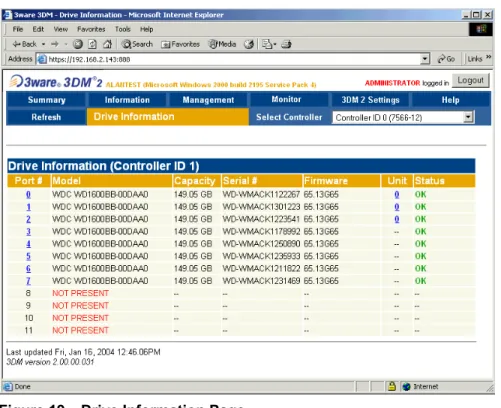
Drive Information Page . . . 50
SMART Details About Drive at Particular Port Page . . . 52
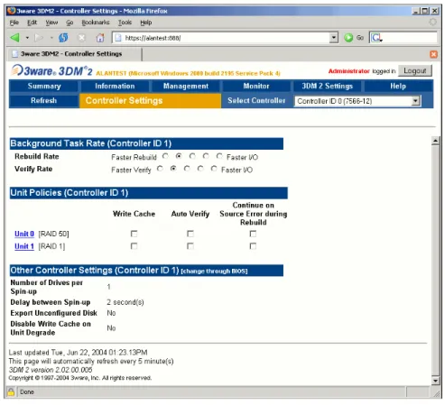
Controller Settings Page . . . 53
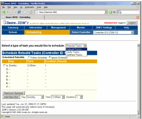
Scheduling Page . . . 56
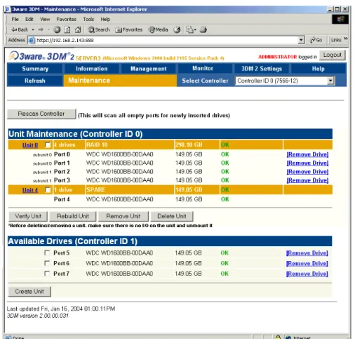
Maintenance Page . . . 58
Alarms Page . . . 65
Battery Backup Page . . . 66
3DM 2 Settings Page . . . 69
Configuring Your Controller . . . 73
Viewing Information About Different Controllers . . . 73
Viewing Controller Policies in 3DM . . . 75
Setting Policies for a Controller through 3BM . . . 76
Exporting JBOD Disks . . . 77
Enabling and Setting Up Staggered Spinup . . . 78
Disabling Write Cache on Unit Degrade . . . 79
Configuring Units . . . 81
Configuring Units in 3DM via the Maintenance Page . . . 82
Configuring Units in 3BM via the main 3BM Screen . . . 82
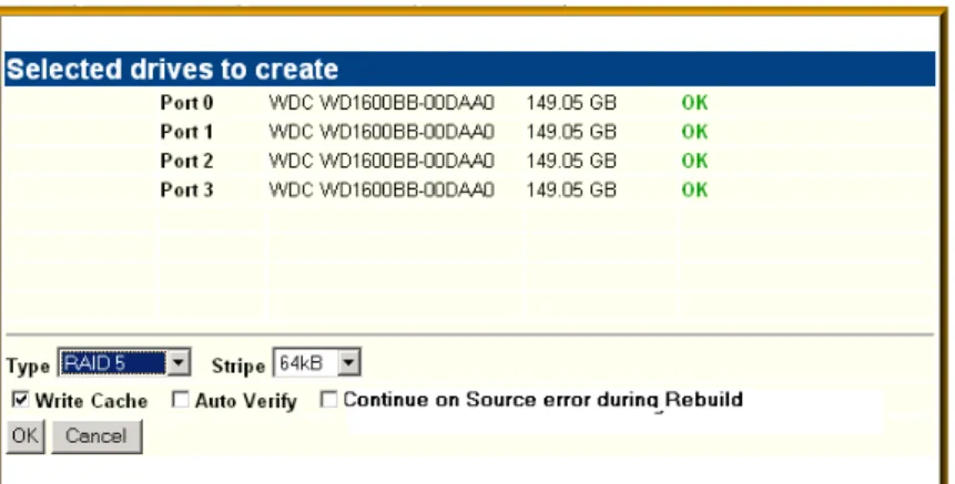
Creating a New Unit . . . 83
Creating a Unit through 3DM . . . 84
Creating a Unit through 3BM . . . 85
Ordering Units in 3BM . . . 88
Partitioning and Formatting Units . . . 88
Creating a Hot Spare . . . 89
Specifying a Hot Spare through 3DM . . . 90
Specifying a Hot Spare through 3BM . . . 90
Enabling and Disabling the Unit Write Cache . . . 91
Enabling and Disabling the Unit Write Cache through 3DM . . . 92
Enabling or Disabling the Write Cache through 3BM . . . 92
Setting Unit Policies through 3DM . . . 93
Changing An Existing Configuration . . . 94
Deleting a Unit . . . 95
Deleting a Unit through 3DM . . . 96
Deleting a Unit through 3BM . . . 98
Removing a Unit . . . 99
Removing a Unit Through 3DM . . . 100
Removing a Unit Through 3BM . . . 101
Moving a Unit from One Controller to Another . . . 102
Unlocking Drives Configured on a 9000 Series Controller . . . 102
Adding a Drive through 3DM . . . 103
Removing a Drive . . . 103
Rescanning the Controller . . . 106
Viewing Alarms . . . 111
Downloading an Error Log . . . 112
Viewing SMART Data About a Drive . . . 112
About Background Tasks . . . 113
About Initialization . . . 113
Auto Initialization After Power Failure . . . 114
About Rebuilds . . . 115
About Verification . . . 115
About Self-tests . . . 117
Setting Background Task Rate . . . 117
Scheduling Background Tasks . . . 118
Viewing Current Task Schedules . . . 119
Turning On or Off Use of a Task Schedule . . . 120
Removing a Task Schedule . . . 120
Adding a New Task Schedule Slot . . . 121
Selecting Self-tests to be Performed . . . 122
Rebuilding Units . . . 122
Rebuilding a Unit Through 3DM . . . 123
Rebuilding Units through 3BM . . . 124
Cancelling a Rebuild and Restarting It with a Different Drive . . . 127
Verifying Units . . . 127
Verifying a Unit through 3DM . . . 128
Verifying a Unit through 3BM . . . 128
Maintaining Your Controller . . . 131
Determining the Current Version of Your 3ware Driver . . . 131
Updating the Driver and Firmware . . . 132
Updating the 3ware Driver and Firmware Under Windows . . . 133
Updating the 3ware Driver Under Windows . . . 135
Updating the 3ware Driver Under Red Hat . . . 145
Updating the 3ware Driver Under SuSE . . . 146
Updating the 3ware Driver Under FreeBSD . . . 147
Viewing Battery Information . . . 147
Testing Battery Capacity . . . 148
Troubleshooting: Problems and Solutions . . . 151
Before Contacting Customer Support . . . 151
Problems in 3DM . . . 153
Hardware Installation . . . 153
Software Installation . . . 154
Screen Display Messages . . . 155
AEN Messages . . . 156
Glossary . . . 171
Appendix A. Compliance and Conformity Statements . . . 177
Federal Communications Commission Radio Frequency Interference Statement 177 Microsoft Windows Hardware Quality Lab (WHQL) . . . 178
European Community Conformity Statement . . . 178
Appendix B. Warranty, Technical Support and Service . . . 179
Limited Warranty . . . 179
Exclusions . . . 179
State Law Provisions . . . 180
Obtaining Warranty Protection . . . 180
About This Guide
3ware 9000 Series Serial ATA RAID Controller User Guide provides instructions for configuring and maintaining your 3ware controller. This guide assumes that you have already installed your controller in your system. If you have not yet done so, see 3ware 9000 Series Serial ATA RAID Controller Installation Guide for instructions.
How this Guide is Organized
There are often multiple ways to accomplish the same configuration and maintenance tasks for your 3ware RAID controller. This manual includes instructions for performing tasks using two tools: one at the BIOS level (3ware BIOS Manager, or 3BM) and one that runs in a browser (3ware Disk Manager 2, or 3DM 2). You can also perform many tasks at the command line, using 3ware’s Command Line Interface (CLI). The CLI is described in a separate manual, available from the 3ware software CD and from 3ware’s website: 3ware 9000 Series Serial ATA RAID Controller CLI Guide.
Basic information about using the two tools (3BM and 3DM), such as starting the tool, navigating between screens, and so forth, is described in sections about each of those tools: “3ware BIOS Manager (3BM)” on page 19 and “3ware Disk Manager (3DM 2)” on page 27.
Step-by-step instructions for performing specific tasks are organized by tasks throughout other sections of this guide. For example, the instructions for “Creating a New Unit” on page 83 include information about how to create a unit from 3DM, followed by how to create a unit from 3BM.
Table 1: Sections in this Guide
Section Description
Introduction Provides an overview of product features for the 3ware 9000 series controllers. Includes system requirements and an introduction to RAID concepts and levels.
Getting Started Provides a summary of the steps required to install and set up your 3ware RAID controller. 3ware BIOS Manager (3BM) Describes the basics of using 3BM.
3ware Disk Manager 2 (3DM 2) Describes the basics of using 3DM and includes a reference of all the 3DM pages. Configuring Your Controller Describes how to view details about the
controller, check it’s status, and change configuration settings that affect the controller and all associated drives.
Configuring Units Describes how to configure new units and spares, change existing configurations, and set unit policies.
Maintaining Units Describes how to check unit and drive status, review alarms and errors, schedule background maintenance tasks, and manually start them, when necessary or desirable. Includes explanations of initialization, verify, rebuild, and self-tests.
Maintaining Your Controller Describes how to update the driver, move a unit from one controller to another, and replace an existing 3ware controller with a new one. Also includes information about checking battery status on a BBU (Battery Backup Unit). Troubleshooting Provides common problems and solutions, and
explains error messages.
Glossary Includes definitions for terms used throughout this guide.
Appendices Provides compliance and conformity
statements, warranty information, and tells you how to contact technical support.
Conventions
The following conventions are used through this guide:
3BM refers to the 3ware BIOS Manager
3DM refers to the 3ware Disk Manager, version 2.
In the sections that describe using 3DM, current controller is used to refer to the controller which is currently selected in this drop-down list.
Unit refers to one or more disks configured through 3ware to be treated by the operating system as a single drive. Also known as an array. Array and unit are used interchangeably throughout this manual.
Boldface is used for buttons, fields, and settings that appear on the screen. Monospace font is used for code and to indicate things you type.
Introducing the 3ware 9000
Series Controller
This chapter includes the following sections:
“Product Features” on page 5
“What’s New With the 3ware 9000 Series Controller” on page 6 “System Requirements” on page 6
“Understanding RAID Concepts and Levels” on page 8 “Determining What RAID Level to Use” on page 12
Product Features
The 3ware 9000 Series Serial ATA family includes 9500S-4LP, 9500S-8, 9500S-12, 9500S-8MI, 9500S-12MI.
Features of the 3ware 9000 series controllers include:
Advanced RAID features for greater data protection and management. Support for battery backup provides added data protection in the event of
a power outage.
Support for arrays greater than 2 terabytes
An enhanced firmware platform allows future upgrades. Anticipated
upgrades include on-line capacity expansion (OCE), RAID Level Migration (RLM), Internationalization, and Enclosure Management Services (EMS).
What’s New With the 3ware 9000 Series
Controller
Enhancements and changes from the 7000/8000 Series controllers to the 9000-series controllers include the following:
Single unit capacity scales to over 2 terabytes per controller (64-bit LBA support)
128MB of ECC protected SDRAM, user upgradeable
Variable stripe size, for performance tuning by application
Background initialization of redundant unit for immediate availability
Support for legacy and SATA II OOB staggered drive spin-up
Emergency flash recovery protects against power failure during firmware upgrades
RAID 50 support, which provides increased reliability
Enhanced write cache strategy for higher performance Support for drive-activity LED
Single disk units will allow RAID Level Migration (RLM) and Online
Capacity Expansion (OCE) in a future firmware releases of the 9000 series.
Note: If you migrate JBOD drives from a 7000/8000 series RAID controller to a 9000-series RAID controller, you will need to enable the “Export JBOD” policy in 3ware BIOS Manager. If you want to use these drives for online capacity expansion and RAID migration in the future, 3ware
recommends that you backup the data from the JBOD drives to another drive, create Single-disk units from the JBOD drives, and restore your data.
Code set release 9.1.5 and newer supports the Battery Backup Unit
(BBU), which can preserve the contents of the cache memory for up to 72 hours.
System Requirements
3ware RAID controllers require the following
Workstation-class or server-class motherboard which meets the following criteria:
System Requirements
Note:For all 3ware 9000 series models, install the card in a 64-bit, 66 MHz PCI or PCI-X slot for best performance.
Drives
Depending on the particular model, the 3ware RAID controller may be connected to up to two, four, eight, or twelve Serial ATA drives by the supplied interface cables.
Drives must meet serial ATA (SATA-1) 150 Gb/s standards, but may be of any capacity or physical form factor.
The length of shielded and unshielded interface cables may not exceed 1M (39”) for serial ATA controllers.
Operating System
3ware RAID controllers may be used with:
Windows 2000 (SP3 or newer), Windows XP (SP1 or newer),
Windows Server 2003
Red Hat Linux SuSE Linux
Other versions of Linux using the open source Linux driver FreeBSD
Other Requirements
Adequate air flow and cooling
Adequate power supply for drives
3DM 2 (3ware Disk Manager) displays information in a browser. It requires the following:
Internet Explorer 5.5 and later or Mozilla 1.2 or later
JavaScript must be enabled Cookies must be enabled
For best viewing, screen resolution should be 1024 x 768, with 16-bit
Understanding RAID Concepts and Levels
3ware RAID controllers use a Redundant Array of Inexpensive Disks (RAID) to increase your storage system’s performance and provide fault tolerance (protection against data loss).The following concepts are important to understand when working with a RAID controller:
Arrays and Units. In the storage industry, the term “array” is used to describe two or more disk drives that appear to the operating system as a single unit. When you work with 3ware software, “unit” is the term used to refer to an array of disks that is configured and managed through the 3ware software. Single-disk units can also be configured in the 3ware software.
Mirroring. Mirrored arrays write data to paired drives simultaneously. If one drive fails, the data is preserved on the paired drive. Mirroring provides data protection through redundancy. In addition, mirroring using a 3ware RAID controller provides improved performance because 3ware’s TwinStor technology reads from both drives simultaneously.
Striping. Striping across disks allows data to be written and accessed on more than one drive, at the same time. Striping combines each drive’s capacity into one large volume. Striped disk arrays achieve highest transfer rates and performance at the expense of fault tolerance.
Distributed Parity. Parity works in combination with striping on RAID 5 and RAID 50. Parity information is written to each of the striped drives, in rotation. Should a failure occur, the data on the failed drive can be reconstructed from the data on the other drives.
Hot Swap. The process of exchanging a drive without having to shut down the system. This is useful when you need to exchange a degraded drive or a bad drive in a redundant array.
Array Roaming. The process of swapping out or swapping in a
configured unit without having to shut down the system. This is useful if you need to move the unit to another controller.
Disk Roaming. The process of removing a unit from a controller and putting it back later, either on the same controller, or a different one, and having it recognized as a unit. The disks may be can be attached to different ports than they were originally attached to, without harm to the data. The disks may be attached to the same ports or different ports on the controller.
For definitions of other terms used throughout the documentation, see the “Glossary” on page 171.
Understanding RAID
Available RAID Configurations
The following RAID levels and configurations are available for drives attached to a 3ware RAID controller:
RAID 0 RAID 1 RAID 5 RAID 10 RAID 50 Single Disk JBOD Hot Spare RAID 0
Provides striping, but no mirroring or redundancy of any kind. Striped disk arrays achieve high transfer rates because they can read and write data on more than one drive simultaneously. The stripe size is configurable in the 3ware BIOS Manager (3BM) and in the 3ware Disk Manager (3DM 2). Requires a minimum of two drives.
When drives are configured in a striped disk array (see Figure 1), large files are distributed across the multiple disks using RAID 0 techniques.
Striped disk arrays give exceptional performance, particularly for data intensive applications such as video editing, computer aided design and geographical information systems.
RAID 0 arrays are not fault tolerant. The loss of any drive results in the loss of all the data in that array, and can even cause a system hang, depending on your operating system. RAID 0 arrays are not recommended for high
availability systems unless additional precautions are taken to prevent system hangs and data loss.
Figure 1. RAID 0 Configuration Example
RAID 1
Figure 2). This gives your system fault tolerance by preserving the data on one drive if the other drive fails. Fault tolerance is a basic requirement for mission critical systems like web and database servers.
3ware uses a patented technology, TwinStor®, on RAID 1 arrays for improved performance during sequential read operations. With TwinStor technology, read performance is twice the speed of a single drive during sequential read operation.
The adaptive algorithms in TwinStor technology boost performance by distinguishing between random and sequential read requests. For the
sequential requests generated when accessing large files, both drives are used, with the heads simultaneously reading alternating sections of the file. For the smaller random transactions, the data is read from a single optimal drive head.
Figure 2. RAID 1 Configuration Example
RAID 5
Combines striping data with parity (exclusive OR) to restore data in case of a drive failure. This array type provides performance, fault tolerance, high capacity, and storage efficiency. Requires a minimum of three drives. Parity information is distributed across all drives rather than being
concentrated on a single disk (see Figure 3). This avoids throughput loss due to contention for the parity drive.
Figure 3. RAID 5 Configuration Example
RAID 10
This array is a combination of RAID 1 with RAID 0. Striped and mirrored
RAID 5 A Blocks 0 parity A4 A3 A2 A1 1 parity B4 B3 B2 2 parity C4 C3 C1 3 parity D4 D2 D1 4 parity E3 E2 E1 B0 C0 D0 E0
Understanding RAID
When drives are configured as a striped mirrored array, the disks are
configured using both RAID 0 and RAID 1 techniques, thus the name RAID 10 (see Figure 4). A minimum of four drives are required to use this
technique. The first two drives are mirrored as a fault tolerant array using RAID 1. The third and fourth drives are mirrored as a second fault tolerant array using RAID 1. The two mirrored arrays are then grouped as a striped RAID 0 array using a two tier structure. Higher data transfer rates are
achieved by leveraging TwinStor and striping the arrays. RAID 10 is available on the four, eight, and twelve port 3ware Serial ATA RAID Controllers.
Figure 4. RAID 10 Configuration Example
RAID 50
This array is a combination of RAID 5 with RAID 0. This array type provides fault tolerance and high performance. Requires a minimum of six drives. Several combinations are available with RAID 50. For example, on a 12-port controller, you can have a grouping of 3, 4, or 6 drives. A grouping of 3 means that the RAID 5 arrays used have 3 disks each; four of these 3-drive RAID 5 arrays are striped together to form the 12-drive RAID 50 array.
Single Disk
A single drive that has been configured as a unit through 3ware software. (3BM, 3DM 2, or CLI). Like disks in other RAID configurations, single disks contain 3ware Disk Control Block (DCB) information and are seen by the OS as available units.
Single drives are not fault tolerant and therefore not recommended for high availability systems unless additional precautions are take to prevent system hangs and data loss.
JBOD
A JBOD is an unconfigured disk attached to your 3ware RAID controller. JBOD configuration is no longer supported in the 3ware 9000 series. AMCC recommends that you use Single Disk as a replacement for JBOD, to take advantage of advanced features such as caching, OCE, and RLM.
JBOD units are not fault tolerant and therefore not recommended for high availability systems unless additional precautions are taken to prevent system hangs and data loss.
Hot Spare
A single drive, available online, so that a redundant array can be automatically rebuilt in case of drive failure.
For additional information about RAID levels, see the article “RAID Primer” on the 3ware website, at: http://www.3ware.com/products/pdf/
RAID_Primer.pdf.
Determining What RAID Level to Use
Select the RAID configuration to use based on the applications to be used on the system, whether performance or data protection is of primary importance, and the number of disk drives available for use.
Review the information under “Understanding RAID Concepts and Levels” on page 8 to determine the type of RAID configuration most appropriate for your needs and use the tables below to determine what RAID levels are available, based on your particular controller model and the number of available drives.
The RAID configurations available to you are determined by the number of ports on your controller, and the number of drives attached to those ports. You can configure all drives in one unit, or you can configure multiple units, if you have enough drives.
Table 2: Possible Configurations Based on Number of Drives # Drives Possible RAID Configurations
1 Single drive or hot spare
2 RAID 0 or RAID 1
3 RAID 0
RAID 1 with hot spare RAID 5
4 RAID 5 + hot spare RAID 10
Combination of RAID 0, RAID 1, single disk 5 RAID 5 + hot spare
RAID 10 + hot spare
Understanding RAID
Drive Capacity Considerations
The capacity of each drive is limited to the capacity of the smallest drive in the array. The total array capacity is defined as follows:
Through drive coercion, the capacity used for each drive is rounded down so that drives from differing manufacturers are more likely to be able to be used as spares for each other. The capacity used for each drive is rounded down to the nearest GB for drives under 45 GB (45,000,000,000), and rounded down to the nearest 5 GBytes for drives over 45 GB. For example, a 44.3 GB drive will be rounded down to 44 GBytes, and a 123 GB drives will be rounded. down to 120 GBytes. For more information, see the discussion of drive coercion under “Creating a Hot Spare” on page 89.
6 or more RAID 50
Depending on the number of drives, a RAID 50 may contain from 2 to 4 subunits. For example, with 12 drives, possible RAID 50 configurations include 2 subunits of 6, 3 subunits of 4, or 4 subunits of 3. With 10 drives, a RAID 50 will contain 2 subunits of 5 drives each.
Combination of RAID 0, 1, 5, 10, hot spare, and single disk
Table 3: Drive Capacity RAID Level Capacity
RAID 0 (number of drives) X (capacity of the smallest drive) RAID 1 capacity of the smallest drive
RAID 5 (number of drives - 1) X (capacity of the smallest drive) Storage efficiency increases with the number of disks: storage efficiency = (number of drives -1)/(number of drives) RAID 10 (number of drives / 2) X (capacity of smallest drive)
RAID 50 (number of drives - number of groups of drives) X (capacity of the smallest drive)
Table 2: Possible Configurations Based on Number of Drives # Drives Possible RAID Configurations
3ware Tools for Configuration and
Management
3ware software tools lets you easily configure the drives attached to your 3ware RAID controller, specifying which drives should be used together as a RAID unit and the type of RAID configuration you want, and designating hot spares for use if a drive degrades.
3ware provides several tools for use in configuring and managing units attached to the 3ware controller:
3BM (3ware BIOS Manager)
3DM 2 (3ware Disk Manager)
3ware CLI (Command Line Interface)
3BM (3ware BIOS Manager)
3BM is a BIOS level tool for creating, deleting, and maintaining disk arrays, rebuilding arrays, designating hot spares, and setting controller policies. 3BM is the tool most frequently used to configure units immediately after
installation of the controller, but can also be used after installation to maintain the controller and associated drives.
For general information about working with 3BM, see “3ware BIOS Manager (3BM)” on page 19.
3DM 2 (3ware Disk Manager)
3DM is a daemon (under Linux) and a service (under Windows) which runs in the background on the controller’s host system, and can be accessed through a web browser to provide ongoing monitoring and administration of the controller and associated drives. 3DM supports hot spare and hot swap for redundant units.
3DM can be used locally (on the system that contains the 9000) or remotely (on a system connected via a network to the system containing the 9000). For details about working with 3DM, see “3ware Disk Manager (3DM 2)” on page 27.
3DM 2 is the current version of the 3ware Disk Manager. Throughout this manual, it is referred to interchangeably as 3DM and 3DM 2.
Monitoring, Maintenance,
and perform maintenance functions such as adding or removing drives, and reconfiguring RAID units online. You also use it to remotely administer controllers in a system by first logging into the system.
The 3ware CLI is described in 3ware 9000 Series Serial ATA RAID Controller CLI Guide.
Monitoring, Maintenance, and
Troubleshooting Features
Several 3ware RAID controller features aid in monitoring and troubleshooting your drives.
SMART Monitoring (Self-Monitoring, Analysis and Reporting Technology) automatically checks a disk drive's health every 24 hours and reports potential problems. This allows you to take proactive steps to prevent impending disk crashes. SMART data is checked on all disk drives (array members, single disks, and hot spares). Monitoring of SMART thresholds can be turned on and off in 3DM. (For details, see “Viewing SMART Data About a Drive” on page 112.)
Staggered Spin Up allows drives that support this feature to be powered-up into the standby power management state to minimize in-rush current at power-up and to allow the controller to sequence the spin-up of drives. Both SATAII OOB and ATA spin-up methods are supported. The standby power management state is persistent after power-down and power-up. You can set the number of drives that will spin up at the same time, and the time between staggers in 3BM (the 3ware BIOS Management utility). For details, see “Enabling and Setting Up Staggered Spinup” on page 78.
Verification and Media Scans. The verify task verifies all redundant units, and checks for media errors on single disks, spares, JBODS and RAID 0 unit members. If the disk drive is part of a redundant unit, error locations that are found and are deemed repairable are rewritten with the redundant data. This forces the drive firmware to reallocate the error sectors accordingly.
Error Correction. Bad sectors can be dynamically repaired through error correction (Dynamic Sector Repair). Reallocation of blocks will try to be based intelligently on the location of the block in relation to the stripe.
Scheduled Background Tasks. Initialize, rebuild, verify, and self-test tasks can all be run in the background, at scheduled times. This lets you choose a time for these tasks to be run when it will be least disruptive to your system. You can also define the rate at which background tasks are performed, specifying whether I/O tasks should be given more processing time, or background rebuild and verify tasks should be given more
Write Cache. Write cache can be enabled or disabled using 3BM, 3DM2 and CLI. When write cache is enabled, data will be stored in system cache, 3ware controller cache, and drive cache before the data is committed to disk. This allows the system to process multiple write commands at the same time, thus improving performance. However when data is stored in cache, it could be lost if a power failure occurred. With a Battery Backup Unit (BBU) installed, the cache stored on the 3ware controller can be restored. For more information, see “Updating the 3ware Driver Under Windows” on page 135.
Getting Started with Your
3ware RAID Controller
Setting up your 3ware RAID controller involves these main steps:
Physically Install the Controller and Drives
Configure the RAID Unit and Drives
Install the Drivers and Make the Operating System Aware of the New Drives
Set Up Management and Maintenance Features
Once the controller and drives have been physically installed, the order in which you perform these steps depends in part on whether one of the units you configure will act as your boot drive.
Physically Install the Controller and Drives
To install your controller and drives, follow the instructions in 3ware 9000 Series Serial ATA RAID Controller Installation Guide. If you do not have a hardcopy of this manual, you can download it from the 3ware website at http:/ /www.3ware.com/support/userdocs.asp
Configure the RAID Unit and Drives
You may want to review the information under “Understanding RAID Concepts and Levels” on page 8 before configuring your drives. This information will help you choose the appropriate RAID level for your situation.
If you will install the operating system on and boot from a drive managed through the new 3ware RAID controller, use the 3ware BIOS Manager (3BM)
Information about using 3BM is also included in this user guide, but the installation guide offers a sequential set of steps for initial installation. If the operating system is already installed on another drive in your system, you can configure the drives through either 3BM or through 3ware Disk Manager (3DM). If you want to use 3DM for configuration, go ahead and boot to the OS, install the drivers and the 3DM 2 software, and then configure your units. For details about using 3DM, see “3ware Disk Manager (3DM 2)” on page 27.
Note: The ability to configure RAID units, single drives, and hot spares through 3DM is new with version 2 of 3DM (3DM 2). If you previously used 3DM version 1.x, configuration was not available in that version.
Install the Drivers and Make the Operating System Aware of the New Drives
Complete instructions for installing drivers and completing the installation under Windows, Red Hat Linux, SuSE Linux, and FreeBSD are provided in
3ware 9000 Series Serial ATA RAID Controller Installation Guide.
You will also find instructions for updating the driver under “Updating the Driver and Firmware” on page 132.
Set Up Management and Maintenance Features
3ware RAID controllers come with software that include a number of features to help you manage and maintain the controller and your configured units. The default settings for these features allow you to begin using your newly configured units right away. You can review and change these features as a final step in your initial setup, or you can make changes to them later, at your convenience. These features include:
Controller and unit policies, such as staggered spinup, use of write cache, and how unconfigured disks (JBODs) are handled
Email notification of alarms and other events
Schedules for when background tasks will be performed, to minimize the
impact on day-to-day performance during peak usage times.
Details about these features are described in this user guide and can be looked up individually. When you first set up your controller, you may want to review these sections in particular:
“Configuring Your Controller” on page 73
3ware BIOS Manager (3BM)
This section describes the basics of using 3ware BIOS Manager (3BM), one of the tools you can use to configure and maintain the units connected to your 3ware 9000-series RAID controller.For information about doing particular tasks in 3BM, refer to the later sections in this guide.
Note: While the basics of working with 3BM for the 9000 series are similar to working with the 3ware Disk Array Configuration utility for the 7000 and 8000 series, the screens have changed, and some additional features are provided. If you have a 7000- or 8000-series controller, the BIOS screens you see will be somewhat different than those shown in this chapter. For instructions specific to the BIOS manager for 3ware 7000- and 8000-series controllers, see the 3ware Escalade ATA User Guide for 7000 & 8000 Series Controllers, available from the 3ware website, http://
www.3ware.com/support/userdocs.asp
This section is organized into the following topics:
“Starting 3BM” on page 20
“Working in the 3BM Screens” on page 22 “Displaying Advanced Details” on page 25
“Getting Help While Using 3BM” on page 25 “Exiting the 3BM Configuration Utility” on page 26
Starting 3BM
You access 3BM during the start-up process for your computer.
To start 3BM
1 Power up or reboot your system.
2 While the system is starting, watch for a screen similar to Figure 5.
Figure 5. 3ware BIOS Screen
3 Press Alt-3 immediatelyto bring up the 3ware BIOS Manager (3BM). Normally your 3ware configuration remains on-screen for just a few seconds. However, if a unit has degraded, the screen indicates the problem and remains on your screen longer.
4 If you have more than one 9000-series controller in your system, a screen lists the available boards. (See Figure 6.) In this case, highlight the board with which you want to work and press Enter.
3ware ATA RAID Controller: Escalade 9500S-12 BIOS: BE9X X.XX.XX.XXX Firmware: FE9X X.XX.XX.XXX Unit 0 - Mirror 111.74GB
Port 0 - IC35L120AVVA07-0 115.03 GB Port 1 - IC35L120AVVA07-0 115.03 GB Following drives will not be exported to OS:
Port 2 - IC35L120AVVA07-0 115.03 GB Unconfigured Disk Port 3 - IC35L120AVVA07-0 115.03 GB Unconfigured Disk Press <Alt-3> to access 3ware BIOS Manager
----Starting 3BM
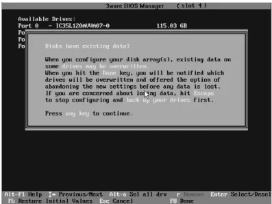
You see a screen similar to Figure 7, warning you that changing your disk array configuration may overwrite data on the disks.
If you plan to make changes to your configuration and need to backup data before continuing, press ESC and do so now. Otherwise, press any key to continue.
Figure 7. Warning Message When you Start 3BM
If a 3BM detects a degraded array, a red message box appears, to alert you to the problem. For information about rebuilding a degraded array, see “Rebuilding Units” on page 122
Note: If you have a combination of 7000/8000-series and 9000-series controllers in your system, the 7000/8000-series controllers are not listed on the selection screen shown in Figure 6. Instead, an additional BIOS summary will appear for the 7000/8000-series controller, similar to Figure 5. To access the BIOS utility for the 7000/8000-series board, press Alt-3 when the information for that controller appears, to enter the BIOS software. Although similar to 3BM, some screens and features are different for the 7000/8000-series. For detailed information, see the version of the 3ware Escalade ATA RAID Controller User Guide that supports the 7000 and 8000 series controllers.
If you have two 9000 controllers that have different versions of the BIOS installed, they will also appear in different BIOS summaries, and will launch different versions of 3BM.
Working in the 3BM Screens
The main 3BM screen (Figure 8) shows the current configuration for the drives attached to your controller, and a list of any available drives. Unusable and incomplete drives are also shown.
Figure 8. 3BM Main Display
You will see one or more of the following sections in the main 3BM screen:
Available Drives lists any unconfigured, independent drives (JBODs)
that are not associated with an array, and hot spares. If this section does not appear, there are no available drives.
Exportable Units lists the existing units, along with the drives contained in each. These are the units that will be available to the operating system when you boot your computer. If this section does not appear, no units have been configured.
If you have more than one unit, the boot unit is the one at the top of the list. (You can change the order by highlighting a unit and pressing the PgUp or PgDn key.)
Unusable Arrays lists any RAID configuration missing too many drives
to construct the unit. For example, a RAID 5 unit with two or more drives missing would appear in this list.
Incomplete Drives and Others lists drives that are remaining from a unit with missing or failed drives, drives that are not usable, and drives that were part of a unit on a 3ware 7000/8000-series controller, and contain data that needs to be updated before your 3ware 9000 series controller can use them. (If you want to move a unit from a 7/8000 controller to the 9000
Working in the 3BM Screens
section “Replacing an Existing Controller with a New Controller,” in the
3ware 9000 Series Serial ATA RAID Controller Installation Guide.) When some of the drives are remaining from a unit, you can power down and add the missing drives to complete the unit. To use drives that are listed here in other units, you must first delete them. For more
information, see “Deleting a Unit” on page 95.
If any of the sections are not shown, it means that there are no items of that type connected to the controller.
Table 4 lists how to move around and select information in the 3BM screens. When these commands are available in 3BM, they appear at the bottom of the 3BM screen.
Table 4: Working in 3BM
To do this Use these keys Move between units or drives in a list, and
between fields, and buttons
Up and Down Arrow Keys OR
Left and Right Arrow Keys OR
Tab and Shift+Tab Select (or unselect) what is currently
highlighted.
A selection may be a drive in a list of drives, a button at the bottom of the screen, or a field in the middle of the screen.
In lists, an asterisk appears to the left of selected drives or units
Enter or the Spacebar
Display a drop-down list of available choices in a field
Enter
Move between choices in a field list Up and Down Arrow Keys
Select all available drives Alt-A
Highlight one of the primary buttons on the main screen:
Create Delete Maintain Rebuild Policy BBU Alt+C Alt+D Alt+M Alt+R Alt+P Alt-B Specify (or unspecify) a drive as a hot S
Unlock the drives in a unit, so that they can be removed and used with a controller other than a 9000-series controller.
R (Remove)
Return to starting values for this session in the 3ware BIOS Manager
F6
Note: F6 cannot bring back previous policy settings; they are saved when you exit the Policy screen.
Display the Advanced Detail screen, where you can see the software versions (BIOS, Firmware, monitor) and slot # of the 3ware card.
Shift+F5
Return to the main 3ware BIOS Manager screen, from the Advanced Details screen
Any key
Move a highlighted unit up or down in the list of exportable units
(The top-most unit will become the bootable unit, if you install the OS.)
Page Up Page Down
[Available only when there are multiple units and a unit is highlighted.] Display context sensitive help F1 or Alt-F1
If you have multiple 3ware controllers in your system, return to the board selection screen.
Esc
Exit the utility and save or abandon all changes.
Esc Exit the utility and save all changes F8 Table 4: Working in 3BM
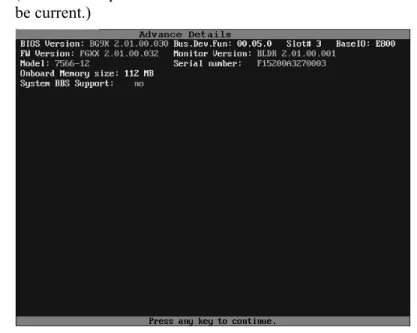
Displaying Advanced Details
Displaying Advanced Details
The Advanced Details screen shows you details about your controller, and about the version of associated software installed on your system.
To see the advanced details
Press Shift+F5 from the main screen.
(Note that the particular versions shown in the screen shot below may not be current.)
Figure 9. Advanced Detail Screen To return to the main screen
Press any key.
Getting Help While Using 3BM
You can get help with using 3BM while you are in the BIOS manager.
Press F1 or Alt-F1 at any time.
A description of the basic 3BM tasks appears.
Exiting the 3BM Configuration Utility
When you are ready to exit the 3BM configuration utility, you have the option to save the configuration changes you have made, or to discard the changes.
To save your configuration modifications
1 Press the F8 or Esc key.
A list of affected drives appears, and a messages ask you to confirm the configuration.
2 Type Y.
The booting process resumes.
To exit without saving changes
1 Press Esc.
2 If you have unsaved changes, 3BM will ask you whether you want to save the changes and exit, or exit without saving the changes.
If you want to exit without saving changes, type N.
If you change your mind and want to save the changes, type Y.
Exception: Any changes made to policies are saved when you leave the Policy screen. Pressing F8 is not required to save those changes. For details about changing policies, see “Setting Policies for a Controller through 3BM” on page 76.
3ware Disk Manager (3DM 2)
Note: 3DM 2 includes software developed by the OpenSSL Project for use in the OpenSSL Toolkit (http://www.openssl.org/).
3ware Disk Manager 2 (3DM 2), allows you to view the status of and manage 3ware RAID controllers and associated drives. 3DM runs as a service under Microsoft Windows, and as a daemon under Linux. When it is running, you can use your browser to view status and perform administrative tasks locally or remotely.
3DM 2 can display information about 3ware RAID 7000-, 8000- and 9000-series RAID controllers. However, some version 2 features are only available for 9000-series controllers.
Two levels of access are provided: user and administrator. Users have view-only access—they can check the status of drives and units—while
Administrators can view and make changes, using 3DM to configure RAID units and designate hot spares, and to perform maintenance tasks on RAID units.
In this section overview, information is organized into the following topics:
“Browser Requirements for 3DM” on page 28 “Installing 3DM” on page 29
“Starting 3DM and Logging In” on page 34 “Working with the 3DM Screens” on page 37
“Setting Up 3DM Preferences” on page 41 “3DM 2 Reference” on page 45
“3DM 2 Reference” on page 45, which contains information about the
For additional information about doing particular tasks in 3DM, see the remaining sections in this guidehttp://www.3ware.com/support/userdocs.asp.
Browser Requirements for 3DM
3DM runs in most current web browsers. Tested and supported browsers include:
Mozilla 1.2 and above
Internet Explorer 5.5 and above
Additional requirements:
JavaScript must be enabled Cookies must be enabled
For best viewing, use a screen resolution of 1024 X 768 or greater, and set
colors to 16 bit color or greater.
Note: Because 3DM may be viewed in different browsers, the format and style of the 3DM browser windows illustrated in this chapter are examples only. (Screenshots were taken in Internet Explorer.) The actual “look” of the windows will depend on the browser, 3DM version and operating system in use.
Setting up Mozilla
Details about accessing all ports, including port 888, by adding a list of ports to /Mozilla/default/all.js
Note: For security reasons, some web browsers do not allow connections to certain ports including port-1080 and 888. To override this on a per-port basis, the Mozilla release notes
recommend to add a comma-separated list of ports to default/all.js (in your Mozilla installation directory). For example, to unblock port 888, use the following line:
pref(“network.security.ports.banned.override”, “888”) This file is located at:
Installing 3DM
Installing 3DM
3DM 2 can be installed from the main 3ware CD that came with your 3ware RAID controller. You can also download the current version from the website at http://www.3ware.com/support/download.asp.
3DM must be installed on the system in which the controller is installed. 3DM does not have to be installed on remote systems in order to remotely manage a 3ware controller.
During installation, you will be asked to enter the following preferences for 3DM use. (Each of these preferences can be changed later, from within 3DM.)
The HTTP port to be used as the listening port Whether remote access will be allowed
Whether you want email alerts to be sent when errors occur, and who
should receive them
Installing 3DM on a Microsoft Windows system
The 3ware RAID controller works with Windows 2000, Windows XP, and Windows Server 2003. The latest service packs should be installed for any Windows release.
To install 3DM on a Windows system
1 Insert the 3DM CD-ROM and click Install 3DM 2 when the menu appears.
Or, if you downloaded 3DM from the website, find the file
3DM2_x86.exe or 3DM2_AMD64.exe and double-click it to launch the setup.
2 If a command window opens, press any key to begin the installation process.
3 When the License Agreement screen appears, read and agree to the license information; then let the InstallShield Wizard guide you through the installation process.
4 On the 3DM Remote Monitoring and Security Configuration screen (see Figure 10), use the settings to specify these things:
To change the HTTP port that 3DM will use as a listening port, check
the first box.
If you do not know which port to use, leave the box unchecked and use the default port.
When the second checkbox is checked, only localhost connections are allowed. Internet and Intranet connections are not allowed.
(You can change this setting later in 3DM.)
Figure 10. 3DM Remote Monitoring and Security Configuration Display
5 If the 3DM HTTP listening port setup screen appears, enter the HTTP port you want to use.
This screen only appears when you check the first box on the 3DM Remote Monitoring and Security Configuration screen.
(You can change this setting later within 3DM.)
6 On the E-mail Notification Preferences screen (see Figure 11) use the fields to specify initial email settings.
Note: If you do not want email alerts to be sent to anyone, leave “None” in these fields and click Next to go on to the next
screen.
In the Server field, enter the name of your email server.
If you do not know your server name, ask your system administrator or check the e-mail preferences or setup options on your e-mail client.
In the Recipients field, enter the e-mail address of the user who
should receive the 3DM e-mail status messages.
You may enter multiple e-mail addresses, separating each entry with a comma (,).
Installing 3DM
In the Sender field, enter the email address from which the email
notifications will be sent. This is typically the local host name. (You can change these settings later within 3DM.)
SCSI
Figure 11. 3DM E-mail Notification Preferences
7 Continue with the installation as prompted, clicking Next to move to the next screen, and Finish when you reach the last screen.
3DM Installation gives you the option of starting 3DM and opening the browser window.
8 If you elect to launch the web interface, a Security Alert may appear, as shown in Figure 12. Click Yes continue.
You may install the certificate if you do not want to see this alert in the future. To do so, click View Certificate and then click Install Certificate.
Figure 12. Security Alert dialog box
Notes:
You can start 3DM later by choosing 3DM from the Start menu. If you change, add, or remove an IP address, or change the
machine name of the machine on which you have installed 3DM 2, you will need to recreate the security certificate. You can do so by re-installing 3DM 2, or by deleting the file 3dm2.pem and
restarting the 3DM 2 service. Under Windows, this file is located in the same directory in which you installed 3DM 2. Under Linux, the file resides in /etc/3dm2. You may also want to delete the installed/cached security certificate from your browser.
Uninstalling 3DM under Microsoft Windows
Use the Add or Remove Programs control panel to uninstall 3DM.
From the Startup menu, choose Control Panels > Add or Remove Programs.
In the Add or Remove Programs control panel, select 3DM and click Change/Remove.
Installing 3DM for Linux or FreeBSD
You can install 3DM from the command line, or from a GUI. The steps below describe how to install 3DM from the command line. If you are using a GUI, you can access the CD-ROM and folders from the windows in the GUI.
Note: If you downloaded 3DM_Linux.zip from the website, unzip the file to root (or to any other working directory) and change Directory (CD) to that directory (for example: /root). Then start
the following procedure at step 3, substituting /mnt with /root or
your installation directory.
To start the installation
1 Insert the 3ware software installation ROM for Linux into the CD-ROM drive.
2 Mount the CD-ROM disk:
mount /dev/cdrom /mnt
3 Change the directory and run the install script: For Linux:32-bit x86 systems
cd /mnt/packages/3dm2/linux/x86 ./install.3dm
Installing 3DM
For FreeBSD 32-bit x86 systems:
cd /mnt/packages/3dm2/freebsd/x86 ./install.3dm
To specify initial setup for 3DM 2
During installation, you will be prompted with a series of questions that determine initial 3DM settings. You can change these later, from within 3DM. (The first question appears for Linux, but not for FreeBSD.)
1 Was RPM used to install the Escalade driver and/or 3DM?
The default answer is no.
2 Please enter the location of the help documentation (default is /usr/local/doc/3dm)
Press Enter to accept the default location and display the next question, or enter the path at which you want the documentation to be installed.
3 Would you like to have e-mail notification enabled (Y/N)?
E-mail notification sends an email message when an event occurs. The default answer to this question is “yes”.
If you enable e-mail notification you will be asked to provide additional information: the name of the mail server, the user name for the person who will send the E-mail notification (typically the local host name) and the user name for the person who will receive the e-mail notification (typically the system administrator).
Please enter the name of your mail server: (default is local host name)
Please enter the name of the user you want sending e-mail notification: (default is root)
Please enter the name of the user you want receiving e-mail notification: (default is 3ware_admin)
To enter multiple e-mail addresses, separate them by a comma or a semicolon:
4 Please enter the port number you would like to use for web monitoring (default is 888)
If you do not know what port to use, select the default:
5 Would you like 3DM connection security to limit connections to localhost only? (default is yes)
If you want to be able to use 3DM for remote administration, change this to No.
6 Change the directory and then eject the CD-ROM disk when finished:
cd /home eject cdrom
Uninstalling 3DM under Linux or FreeBSD
To uninstall 3DM for Linux or FreeBSD
1 Insert the 3ware software installation CD-ROM into the CD-ROM drive. 2 Mount the CD-ROM disk:
mount /dev/cdrom /mnt
3 Change the directory and run the uninstall script:
(For FreeBSD, replace “linux” with “freebsd” in the path shown in this step.)
cd /mnt/packages/3dm2/linux/x86 ./install.3dm --u
Note that if you downloaded 3DM from the web, replace “/mnt/” in the previous command with “/root/”
4 Eject the CD-ROM disk when finished:
cd /home eject cdrom
Note: If 3DM Linux is reinstalled or restarted, close any open web browsers before starting 3DM again to close the server socket.
Starting 3DM and Logging In
3DM runs as a service under Windows, and as a daemon under Linux. It is a good idea to leave 3DM running on the system that contains your 3ware RAID controller. That way email alerts can be sent by 3DM, and
administrators can manage the controller remotely, if remote administration is enabled.
You can access the 3DM screens to check status information and manage your 3ware RAID controller by logging in to the 3DM screens in your browser.
Starting 3DM and Logging In
Starting 3DM under Linux
3DM should start automatically after installation and upon bootup.
To start 3DM manually
1 Login as root. 1 Afterwards, type:
For Red Hat Linux:
/etc/rc.d/init.d/3dm start
For SuSE Linux:
/etc/rc.d/3dm start
2 Open your browser and enter the URL for your system.
The default URL is https://localhost:888/ for 32-bit versions of
Linux.
For 64-bit versions of Linux, use: http://localhost:888/
(Note that 32-bit versions require https, while 64-bit versions require http—without the “s.”)
You can also replace “localhost” with the IP address of the computer that contains the 3ware controller. For example: https://<IP address>:888/
Note: If you are using a 64-bit AMD processor with a 64-bit version of Linux, use “http://” instead of “https://”.
The 3DM login screen appears.
Starting 3DM under Microsoft Windows
From the Start menu, choose Programs > 3ware > 3DM 2.
Your default browser opens and displays the URL for your local controller.
The default URL is https://localhost:888/.
You can also replace “localhost” with the IP address of the computer that contains the 3ware controller. For example:
https://<IP address>:888/
Note: If you close your browser, 3DM continues to run in the background on the system.
Viewing 3DM Remotely via a Standard Web Browser
When remote administration is enabled, you can use 3DM to check status and administer your 3ware RAID controller from a browser on any computer, over an internet connection.You do not need to install the 3DM software on the remote computer. Remote connections can be enabled or disabled from the 3DM 2 Settings Page.
In the address line of your browser, enter the URL or IP of the system
containing the 3ware RAID controller.
If you don’t know the URL or IP for the system, you can contact your network administrator or from a Windows command prompt, type
ipconfig. From a Linux command prompt, type ifconfig.
Logging In
When you first view 3DM in a browser, you must log in before you can view or change any information.
Two levels of access are provided:
Users can check the status of the controller, units, and drives attached to
it.
Administrators can check status, configure, and maintain the equipment.
(Administrator and User status in 3DM is not related to Administrator/User settings in the operating system.)
To log in to 3DM
1 On the 3DM logon screen, select whether you are a User or Administrator.
2 Enter your password and click Login.
If you are logging in for the first time after installing 3DM, the default password for both User and Administrator is 3ware.
Note: If you forget the passwords, uninstalling and reinstalling 3DM resets the passwords to 3ware.
Working with the 3DM Screens
Working with the 3DM Screens
3DM’s features are organized on a series of pages you view in your browser. After you log in to 3DM, the Summary page shows a list of controllers installed in the computer at the URL you specified.
Note: If you expect to see a controller that is not listed, it may not be compatible with the driver that is loaded; a firmware flash upgrade may be required.
Figure 13. 3DM Main Screen
The menu bar across the top of the screen gives you access to other pages in 3DM. You can move between pages by using the menu bar, or by clicking a link on the page.
The main area of the page provides summary or detail information about your 3ware RAID controller and the resources connected to it.
As you work in 3DM, the Messages area just below the menu bar displays information about the results of commands you have selected.
3DM Menus
The 3DM menu bar groups access to a number of 3DM pages on menus, and provides direct link access to others.
Figure 14. 3DM Menu Bar
Status information is available from the Information menu. You can view controller, unit, and drive information for a particular controller.
The Management menu gives you access to tasks used for managing controller-level settings (background task rate, enabling of unit write cache, and policies that affect all units managed by the controller), tasks that can be scheduled (rebuild, verify, and self-test), and maintenance of individual units. Unit configuration can also be done through the Management > Maintenance page.
The Monitor menu gives you access to the Alarms page and the BBU page. The Alarms page shows a list of alarms, including the specific alarm message, and the exact date and time it occurred. The BBU page shows the status of a Battery Backup Unit (BBU), if one is installed, and allows you to test the battery.
The 3DM 2 Settings page lets you set preferences, including email
notification for alarms, passwords, page refresh frequency, whether remote access is permitted, and the incoming port which 3DM will use for listening. Help lets you access information about using 3DM, and provides access to an electronic copy of this User Guide.
Working with the 3DM Screens
Viewing Information About Different Controllers in
3DM
If you have more than one controller in the system, you select the one you want to see details about from the drop-down list at the right of the menu bar. This drop-down is available on all pages that provide controller-specific features.
Note: Throughout these instructions, current controller is used to refer to the controller which is currently selected in this drop-down list.
Refreshing the Screen
You can refresh the data on the screen at any time by clicking Refresh Page in the menu bar. This causes 3DM to update the information shown with current information from the controller and associated drives.
Automatic refreshes can also be set. For details, see “Setting the Frequency of Page Refreshes” on page 43.
Note: If you click Refresh on the browser window, you will be taken back to the Summary page.
3DM Screens and What They're Used For
Table 5 shows a list of the pages you work with in 3DM and describes what they are used for. Details about each page and the fields and features on it are provided in the section “3DM 2 Reference” on page 45. The page names in Table 5 provide links to details about that page.
Table 5: List of 3DM Pages 3DM Page Description Controller Summary
Page
Provides basic information about each 3ware RAID controller in your system.
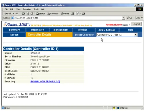
To see this page, click Summary in the menu bar. Controller Details
Page
Provides detailed information about the current controller.
To see this page, choose Information > Controller Details from the menu bar.
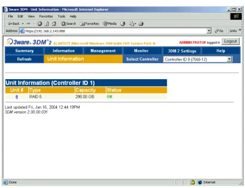
Unit Information Page Shows a list of the units on the current controller and provides summary information about each unit. To see this page, choose Information > Unit Information from the menu bar or click an ID number on the Controller Summary.
Unit Details Page Shows details about a particular unit.
To see this page, click an ID number on the Unit Information page.
Drive Information Page
Shows a list of drives on the current controller and provides summary information about each drive. To see this page, choose Information > Drive Information from the menu bar.
SMART Details About Drive at Particular Port Page
Shows the SMART data for a specific drive.
To see this page, click the Port # for a drive on the Drive Information page.
Controller Settings Page
Lets you view and change settings that affect the units on the current controller.
To see this page, chooseManagement > Controller Settings from the menu bar.
Scheduling Page Lets you view and change the schedule for tasks that affect all units on the current controller.
To see this page, choose Management > Scheduling from the menu bar.
Maintenance Page Lets you configure new units and make changes to existing units.
To view this page, choose Management > Maintenance from the menu bar.
Alarms Page Shows a list of alarms, including the specific alarm message, and the exact date and time it occurred. To view this page, choose Monitor > Alarms on the menu bar.
Battery Backup Page Shows the status of a Battery Backup Unit (BBU), if one is installed, and allows you to test the battery.
To view this page, choose Monitor > Battery Backup on the menu bar.
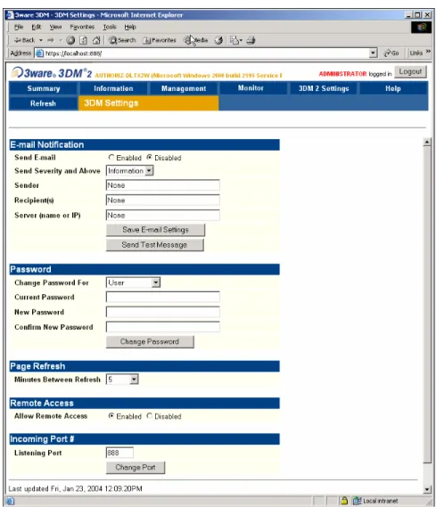
3DM 2 Settings Page Lets you set preferences, including email notification for alarms, passwords, page refresh frequency, whether remote access is permitted, and the incoming port which 3DM will use for listening.
To view this page, click 3DM 2 Settings on the menu bar.
Table 5: List of 3DM Pages 3DM Page Description
Setting Up 3DM Preferences
Setting Up 3DM Preferences
The 3DM 2 Settings page lets you define preference settings that affect the overall operation of 3DM. Most of these settings are specified initially during installation of 3DM.
On the 3DM 2 Settings page you can perform the following tasks:
Setting and Changing 3DM Passwords
Managing E-mail Event Notification Enabling and Disabling Remote Access
Setting the Incoming Port #
Setting the Frequency of Page Refreshes
Setting and Changing 3DM Passwords
3DM provides different access levels for users and administrators.
The Administrator access level allows the user to fully configure 3DM. The User access level allows the user to view pages within 3DM. These passwords work independently of each other.
The default password for both the User and Administrator is “3ware”. Passwords are case sensitive.
You can only change passwords if you are logged in as Administrator. If you change the Administrator password, you will be automatically logged out, and must log back in with the new password.
To set or change the password
1 Click 3DM 2 Settings on the 3DM menu bar.
2 On the 3DM 2 Settings Page, in the Password section, select the type of password you want to change: User or Administrator.
3 Type the current password in the Current Password field.
If you are changing the password for the first time, the factory-set default password is 3ware.
4 Enter the new password in the New Password field and again in the Confirm New Password field.
5 Click the Change Password button to enact the change.
Note: If you forget your password, you can uninstall 3DM and then reinstall it. This will reset the password to the default password,
Managing E-mail Event Notification
3DM can notify you when the 3ware RAID controller requires attention, such as when a disk unit becomes degraded and is no longer fault tolerant.
Event notification can only occur while 3DM is running, so it is
recommended that 3DM be left running on the system that contains the 3ware RAID controller.
When events occur, notification can be e-mailed to one or more recipients. You can specify the type of events for which notifications will be sent by selecting the severity:
Information will send e-mails for all alarms
Warning will send e-mail for alarms with severity of Warning and Error
only.
Error will send e-mail for alarms with severity of Error only.
For more information about events and alarms, see “Viewing Alarms” on page 111.
Event notification is initially set up during 3DM installation, but can be changed on the 3DM 2 Settings page.
To set up event notification
1 Click 3DM 2 Settings on the menu bar.
2 In the E-mail Notification section of the 3DM 2 Settings Page, enter or change the settings you want.
Enable or Disable all notifications.
Set the severity level of events for which e-mail notifications are sent.
Specify the email address of the sender. This will appear in the
“From” field of the e-mail.
Enter the e-mail address(es) to which notifications are sent. (Separate
multiple addresses with a comma (,) or a semicolon (;).
Enter the SMTP server name or IP of your mail server.
3 Click Save E-mail Settings.
To send a test message
You can send a test message to make sure you’ve entered the e-mail notification settings correctly.
Setting Up 3DM Preferences
Enabling and Disabling Remote Access
When remote access is enabled, a user can connect to 3DM over the internet or an intranet, to check status or administer the controller and associated drives.
If remote access is disabled and a user attempts to connect to 3DM remotely, they will see the following error message: “Remote Access to 3DM has been disabled. Please connect using the local machine by entering “localhost” in the URL bar.”
Remote access can be enabled or disabled on the 3DM 2 Settings page.
To enable or disable remote access
1 Click 3DM 2 Settings on the menu bar.
2 In the Remote Access section of the 3DM 2 Settings Page, select either Enabled or Disabled in the Allow Remote Connections field.
The page refreshes, and a message at the top of the screen confirms that remote access has been enabled or disabled.
Setting the Incoming Port #
You can set the port which 3DM uses to listen for incoming messages. If you are not sure which port would be the best to use, leave this set to the default port of 888.
To set the incoming port
1 Click 3DM 2 Settings on the menu bar.
2 In the Incoming Port # section of the 3DM 2 Settings Page, enter the port number in the Listening Port field.
The page refreshes, and a message at the top of the screen confirms that the listening port has been changed.
Setting the Frequency of Page Refreshes
Since the status of the drives attached to your 3ware RAID controller can change while you are viewing information about them in 3DM, it’s important to refresh the page information regularly. That way you can be assured that the information you see in 3DM is current.
You can manually refresh the information on a page by clicking Refresh Page in the menu bar. But you can also have 3DM refresh the information on a regular basis.