doi:10.1155/2012/876380
Research Article
Loop-Reduction LLL Algorithm and Architecture for
Lattice-Reduction-Aided MIMO Detection
Chun-Fu Liao,
1Li-Wei Chai,
2and Yuan-Hao Huang
1, 21Department of Eelectrical Engineering, National Tsing-Hua University, Hsinchu 30013, Taiwan
2Institute of Communications Engineering, National Tsing-Hua University, Hsinchu 30013, Taiwan
Correspondence should be addressed to Yuan-Hao Huang,[email protected]
Received 7 July 2011; Revised 30 September 2011; Accepted 14 October 2011 Academic Editor: Yin-Tsung Hwang
Copyright © 2012 Chun-Fu Liao et al. This is an open access article distributed under the Creative Commons Attribution License, which permits unrestricted use, distribution, and reproduction in any medium, provided the original work is properly cited. We propose a loop-reduction LLL (LR-LLL) algorithm for lattice-reduction-aided (LRA) multi-input multioutput (MIMO) detection. The LLL algorithm is an iterative algorithm that contains many check and process operations; however, the traditional LLL algorithm itself possesses a lot of redundant check operations. To solve this problem, we propose a look-ahead check technique that not only reduces the complexity of the LLL algorithm but also produces the lattice-reduced matrix which obeys the original LLL criterion. Simulation results show that the proposed LR-LLL algorithm reduces the average number of loops or computation complexity. Besides, it also shortens the latency of clock cycles about 19.4%, 29.1%, and 46.1% for 4×4, 8×8, and 12×12 MIMO systems, respectively.
1. Introduction
To increase the transmission capacity, multiple-input multiple-output (MIMO) system has been proposed for the next generation wireless communication systems, and there-fore the need for a high-performance and low-complexity MIMO detector becomes an important issue. The maximum likelihood (ML) detector is known to be an optimal detector; however, it is impractical for realization owing to its great computational complexity. Addressing this problem, researchers have proposed tree-based search algorithms, such as sphere decoding [1] and K-Best decoding [2], to reduce the complexity with near-optimal performance. On the other hand, channel matrix preprocessing technique, such as lattice-reduction-aided (LRA) detection [3], has been proposed to improve the MIMO detection performance.
The lattice reduction transforms the channel matrix into a more orthogonal one by finding a better basis for the same lattice so as to improve the diversity gain of the MIMO detector. The Lenstra-Lenstra-Lov´asz (LLL) algorithm is a well-known lattice reduction algorithm for its polynomial execution time. In the literature [4], the LLL algorithm is widely employed to improve the lattice-reduction MIMO detection or to reduce the MIMO detection complexity. However, the LLL algorithm has many redundant check
operations that have never been addressed in the literature. These redundant operations lead to many unnecessary computations and thus increase the processing latency and complexity. Therefore, we propose a look-ahead check tech-nique to detect and avoid the unnecessary check operations in the LLL algorithm. This technique not only generates the lattice-reduced matrix which obeys the size reduction and LLL reduction in the original LLL algorithm but also applies to real- and complex-value LLL algorithm [5].
The remainder of this paper is organized as follows. Section 2 briefly describes the signal model for MIMO detection. InSection 3, we introduce the lattice-reduction-aided MIMO detection and the LLL algorithm. InSection 4, we demonstrate the proposed LR-LLL algorithm, and in Section 5 we present the simulation and analysis results. The corresponding hardware architecture and processing cycle counts estimation is shown in Section 6. Finally, we summarize our conclusions inSection 7.
2. System Model
A narrow-band Nr ×Nt MIMO system consisting of Nt transmitters andNrreceivers can be modeled by
INPUT: Q, R, such that H=QR OUTPUT: Q, R, T such that HT=Q R (1) Initialize Q=Q, R=R, T=IN (2)k=2 (3) whilek≤N (4) forp=k−1,. . ., 1 (5) μ= R(p,k)/R(p,p) (6) ifμ /=0 (7) R(1 :p,k)←R(1 :p,k)−μR(1 :p,p) (8) T(:,k)←T(:,k)−μT(:,p) (9) end (10) end (11) if δ|R(k−1,k−1)|2> |R(k, k)|2 +|R(k−1,k)|2
(12) swap columnsk−1 andkin R and T (13) calculate Givens rotation matrixΘ=a−b ab
a= R(k−1, k−1) R(k−1 :k,k−1)andb= R(k,k−1) R(k−1 :k,k−1) (14) R(k−1 :k,k−1 :N)←ΘR(k−1 :k,k−1 :N) (15) Q(:,k−1 :k)←Q(:,k−1 :k)ΘT (16) k←max{k−1, 2} (17) else (18) k←k+ 1 (19) end (20) end Algorithm 1: LLL algorithm.
where x∈ANtis the transmitted signal vector, y∈CNris the
received signal vector, H=[h1, h2,. . ., hNt] represents a
flat-fading channel matrix, and n ∈ CNr is the white Gaussian
noise with varianceσ2
n. All the vectors hiare independent and identically distributed complex Gaussian random vectors with zero means and unity variances. Set A consists of the constellation points of the QAM modulation. Then, we re-formulate the equivalent real channel matrix as follows:
yr= ⎡ ⎣R y Iy ⎤ ⎦=Hrxr+ nr = ⎡ ⎣R(H) −I(H) I(H) R(H) ⎤ ⎦ ⎡ ⎣R(x) I(x) ⎤ ⎦+ ⎡ ⎣R(n) I(n) ⎤ ⎦. (2)
Then, the dimension of HrbecomesN×M, whereM=2Nt andN=2Nr. The vectors yrand nrbelong toRN and xr ∈
AM.
The QR decomposition is often applied in the pre-proc-essing of the MIMO detection because it provides decoding efficiency. Then, the channel matrix Hrcan be expressed by
Hr=QrRr, (3) where Qr ∈RN×Mis an orthogonal matrix and Rr∈RM×M is an upper triangular matrix. By multiplying QTr on both sides of (2), we can obtain
yr=QTryr=Rrxr+ QTrnr, (4) where QTrnr is white Gaussian. In addition, we adopt col-umn-norm-based sorted QR decomposition (SQRD) [6] be-cause it not only enhances detection performance but also reduces the computational complexity of the lattice reduc-tion [7].
3. Lattice Reduction
A lattice L is defined as {t1hr1 + t2hr2 + · · · + tNhrN |
t1· · ·tN ∈ Z}, where{hr1,. . ., hrN ∈ RN} are the basis
vectors. The lattice reduction algorithm aims to find a unimodular matrix T(|det T| =1 and all elements of T are integers) such that a more orthogonal Hr = HrT has the
same lattice as Hr. Then, the signal model becomes
yr=Hrxr+ nr=HrT−1xr+ nr=Hrs + nr. (5) If xr ∈ ZN, T−1x
r = s ∈ ZN. In practice, the transmitted signals xrdo not belong to an integer set; however, we can still transform the signals xr ∈ AN into an integer set by linear operations such as scaling and shifting.
Several lattice-reduction algorithms are described in the literature, and the LLL algorithm [11] is the most popular approach. Because QR preprocessing is often employed in the MIMO detector, the LLL algorithm is then modified for
Q and R matrices [12], as shown in Algorithm 1. In the literature, lines (4) to (19) are often defined as a loop that can be decomposed into two parts: (1) lines (4) to (10) deals with the size reduction operations; and (2) lines (11) to (19) handle LLL reduction operations. The number of iterations performed in the size reduction depends on the index k, and the LLL reduction operation may increase or decrease the indexk depending on the result of the LLL reduction check (δ|R(k−1,k−1)|2 > |R(k,k)|2 +|R(k−1,k)|2).
Therefore, the number of loops certainly depends on the values in the R matrix, and thus the processing latency varies for different channel matrices. Moreover, we find that most of the computational complexity is contributed by the operations when the check conditions (μ /=0 for size reduction andδ|R(k−1,k−1)|2>|R(k,k)|2+|R(k−1,k)|2
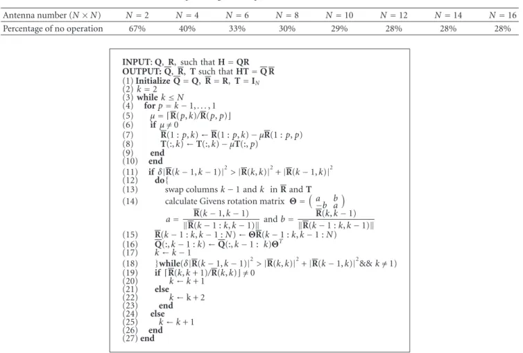
Table 1: The percentage of no operation after indexkis decreased.
Antenna number (N×N) N=2 N=4 N=6 N=8 N=10 N=12 N=14 N=16
Percentage of no operation 67% 40% 33% 30% 29% 28% 28% 28%
INPUT: Q, R, such that H=QR OUTPUT: Q, R, T such that HT=Q R (1) Initialize Q=Q, R=R, T=IN (2)k=2 (3) whilek≤N (4) forp=k−1,. . ., 1 (5) μ= R(p,k)/R(p,p) (6) ifμ /=0 (7) R(1 :p,k)←R(1 :p,k)−μR(1 :p,p) (8) T(:,k)←T(:,k)−μT(:,p) (9) end (10) end (11) ifδ|R(k−1,k−1)|2> |R(k,k)|2 +|R(k−1,k)|2 (12) do{
(13) swap columnsk−1 andk in R and T (14) calculate Givens rotation matrix Θ=a−b ab
a= R(k−1,k−1) R(k−1 :k,k−1)andb= R(k,k−1) R(k−1 :k,k−1) (15) R(k−1 :k,k−1 :N)←ΘR(k−1 :k,k−1 :N) (16) Q(:,k−1 :k)←Q(:,k−1 : k)ΘT (17) k←k−1 (18) }while(δ|R(k−1,k−1)|2>|R(k,k)|2+|R(k−1,k)|2&&k /=1) (19) if R(k,k+ 1)/R(k,k)=/0 (20) k←k+ 1 (21) else (22) k←k + 2 (23) end (24) else (25) k←k+ 1 (26) end (27) end
Algorithm 2: The proposed loop reduction LLL algorithm using look-ahead check technique.
LLL reduction constraints are violated. Most important of all, redundant check operations occur very often when the index k decreases. Thus, the decrease of k is not always necessary because the size and LLL reductions have been checked in the last loop. We calculate the percentage of the redundant decreases of k and list them in the Table 1. We can see that the percentage of the redundant decrease ofk achieves 67% for 2×2 lattice reduction and converge to 28% if the MIMO dimension is larger than 10×10. Therefore, we propose a look-ahead check technique to modify indexk and avoid unnecessary check operations in the original LLL algorithm.
4. Look-Ahead Check
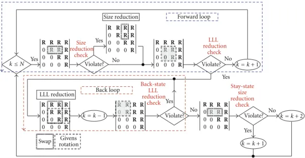
The number of loops is often treated as a benchmark for computation complexity and latency in the literature on LRA MIMO detection [7]. In order to eliminate the redundant check operations in the LLL algorithm, we propose a look-ahead check technique by classifying the original loops to forward loop and back loop. And the loop reduction LLL algorithm is shown inAlgorithm 2. The corresponding flow chart of the proposed algorithm and each loop is shown in Figure 1.
4.1. Back Loop. We define the back loop as the loop that only
contains LLL reduction check and LLL violation processing as shown in Figure 1. We find that the size reduction constraint will not be violated after thekis decreased because the R(k,k) has already been size reduced in the previous processing and is not changed in the column-swapping operation. And the givens rotation will only change thekand
k−1 row while the row value abovek−2 row remains size reduced. That means only LLL reduction check is required in the back loop. This LLL reduction check is named asback -state LLL reduction check to differentiate with the origin one. Because only the LLL reduction part needs to be executed in this back loop, we use a while loop in our algorithm to avoid the redundant size reduction operation. Nonetheless, there is still one case that the size reduction will process. If the division result exactly equals 0.5, the original LLL algorithm will do the size reduction operation in the back loop. But our algorithm will skip. This will produce a different lattice-reduced matrix at last. However, to do the size reduction or not to do in this case will both produce the matrix that obeys the LLL lattice reduction criterion. Although, we cannot prove the performance is the same mathematically, we will show that their performance is the same through the Monte-Carlo simulation in latter section. So the lattice reduction
0 R R R R R R R R R R R 0 0 0 R 0 0 R R 0 R R R R R 0 0 0 R R 0 0 R R R 0 R R R R Size reduction R 0 0 0 R 0 0 R 0 R R R R R 0 0 0 R R 0 0 R R R 0 R R R R LLL reduction 0 0 0 0 R R R 0 R R R R R 0 0 0 R 0 0 R R 0 R R R R No Yes Yes Yes Yes Yes No No No
Swap rotationGivens
Violate? Size reduction check Violate? LLL reduction check Violate? Violate? Back-state LLL reduction check Stay-state size reduction check Forward loop Back loop k≤N k=k+ 2 k=k+ 1 k=k+ 1 k=k−1
Figure 1: The flow chart for loop-reduction LLL algorithm.
Table 2: Average loop of lattice-reduction Algorithms for different antenna numbers.
N 2 4 6 8 10 12
Original LLL algorithm 4.72 16.99 29.73 39.25 46.11 51.56
LR-LLL algorithm 4.6 (97.4%) 15.98 (94%) 27.8 (93.5%) 36.7 (93.5%) 43.53 (94.4%) 48.77 (94.5%)
performance will not suffer any degradation. Using the look-ahead check technique, we can more precisely determine the nextkvalue at the end of each loop.
4.2. Forward Loop. Forward loop is just like the original
loop defined in the previous section except once the LLL reduction is violated, it will enter the back loop. If back -state LLL reduction constraint is not violated, we enter the
stay-state size reduction check to predict the next indexk. Notice that if thestay-state size reduction constraint (μ /=0) is not violated, the LLL reduction constraint must not be violated because the R(k,k) has already been LLL reduced in the previous processing and all values remain unchanged. Therefore, we can also perform thestay-state size reduction check ahead. If thestay-state size-reduction constraint is not violated, we can simply increase the indexk by 2 to skip a redundant LLL reduction and enter the forward loop.
5. Simulation Results
To verify the proposed LLL algorithm, we simulate the LLL-aided MIMO detections based on the MIMO system described inSection 2, and we employ sorted QR decompo-sition in all MIMO detectors. The LLL-reduction parameter
δ equals 0.75, as suggested in [11]. Table 2 shows the average loop numbers of the original and the proposed LLL
algorithms for different antenna numbers. Forward loop and back loop are all counted as a loop in our algorithm. The proposed LLL algorithm can reduce the average number of loops to 93%∼94% of the original LLL algorithm. The BER versus SNR curve is shown for 4×4 and 8×8 MIMO systems in Figures2and3, respectively. The performance is exactly the same for our algorithm and the original LLL algorithm.
We also analyze the computational complexity and laten-cy of our algorithm. The results for 4×4 and 8×8 MIMO systems are listed in Tables3and4. The computation is di-vided to four operations such as addition, multiplication, division, and givens rotation. Our algorithm is lower in total computational complexity and especially in the division which tends to cost more time for computation. The lower ratio is just like the loop-reduced ration. But only average computational complexity cannot clearly show the advantage of our algorithm. Since the original LLL algorithm contains lots of redundant checks operation which are unable to process in parallel, it will result in long average processing time to complete the lattice reduction operation. We try to simulate the latency by parallelizing all the possible opera-tions. The latency counts are as follows: the line (5) to line (9) in our algorithm is counted as one division, one addition and one multiplication. The LLL reduction check operation contains four multiplications and two additions. The column swap operation is counted as no operation delay. The givens rotation counts one at each back loop. And thestay-state size
Table 3: Average computational complexity and latency of lattice-reduction Algorithms for 4×4 MIMO detection.
Algorithm Addition Multiplication Division Givens Rotation Total
LLL 204.6/49.4 238.5/83.4 64.45/64.45 67.34/10.43 575/208.4
LR-LLL 202.79/47.5 234.81/79.5 46.43 (72%)/46.43 67.83/10.43 551.88 (96%)/184 (88.2%)
Table 4: Average computational complexity and latency of lattice-reduction Algorithms for 8×8 MIMO detection.
Algorithm Addition Multiplication Division Givens Rotation Total
LLL 1463.3/141.6 1541.8/220 339.6/339.6 285.8/24.34 3630/725.6 LR-LLL 1462.5/137.21 1527.4/211.1 218.12 (64%)/218.12 287.46/24.49 3504.5 (96%)/591 (81.4%) 5 10 15 20 25 30 SNR No lattice reduction LLL LR-LLL ML 100 10−1 10−2 10−3 10−4 10−5 10−6 BER
Figure 2: BER versus SNR of the 4×4 QR-SIC MIMO detectors
using different lattice-reduction algorithms.
reduction is counted as a division operation. The latency is shown in the Table after the dashed line. The saving is about 22%∼29% and grows with antenna number.
6. Hardware Architecture
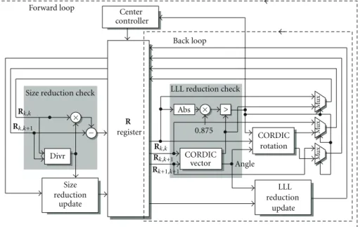
6.1. Top Structure. In this paper, we proposed a very intuitive
structure for our LR-LLL algorithm inFigure 4. The center controller counts the index k by the LLL violation results. And it will send control signals to choose the specific matrix element to the input of the combinational circuit. We can also call size reduction part as size reduction loop and LLL reduction part as LLL reduction loop, respectively. The update circuit for the remaining R matrix, T matrix, and Q matrix are omitted for simplification. In this architecture, CORDIC circuit has two pipelined stages. So it required one cycle for size reduction loop and four cycles for a LLL reduction loop. The traditional LLL algorithm always processes the forward loop which contains the execution of the whole circuit. While using LR-LLL algorithm, some
5 10 15 20 25 30 SNR No lattice reduction LLL LR-LLL ML 100 10−1 10−2 10−3 10−4 10−5 10−6 10−7 10−8 BER
Figure 3: BER versus SNR of the 8×8 QR-SIC MIMO detectors
using different lattice-reduction algorithms.
Table 5: Average Cycle of Lattice Reduction Algorithms for
dif-ferent antenna numbers.
N 4 8 12
Original LLL algorithm 109 451 869
LR-LLL algorithm 89 (81.6%) 320 (70.9%) 469 (53.9%)
forward loops will replace by back loops. The average cycle counts for the LLL algorithm, and our LR-LLL algorithm is listed in Table 5. We can find out that as the antenna number grows, the reduction of average cycle grows. And the FPGA results are shown inTable 6. In [5], the complex-valued LLL lattice reduction algorithm is proved to have lower computational complexity than real-valued system. This is mainly due to the double sized of the real number system comparing to complex number. So the hardware or cycle counts may be larger than the previous two complex number works.
6.2. Other Blocks. The divr block executes the divide and
+ Divr
Size reduction check LLL reduction check
R register Size reduction update LLL reduction update > CORDIC vector CORDIC rotation 0.875 Mu x Mu x Mu x Angle Abs Center controller Forward loop Back loop Rk,k Rk,k Rk,k+1 Rk,k+1 × × − Rk+1,k+1 >
Figure 4: Hardware architecture for LR-LLL algorithm. Table 6: FPGA implementation results and comparison.
Virtex-4 [8] Vertex-4 [9] Virtex-4 [10] Virtex-4 [This work]
LRA algorithm RS-LLL CLLL (modified) CT-LLL LR-LLL
System model Complex Complex Real Real
Slices 4805 3640 11330 4170 Antenna number 4 4 4 4 Frequency 79 MHz 140 MHz 8.7 MHz 53 MHz Ave. cycles/matrix 14 96 5 89 Throughput (M mat/s) 5.6 1.45 1.74 0.59 + MSB MSB MSB 5 0 4 + MSB 5 0001 5 4 5 Stage 1 Mu x Mu x Abs Abs MSB Quotient 4
Stage 2 Stage 3 Stage 4
Rin1
Rin2
−
≥ ≪3
Figure 5: Division and round circuit.
division architecture. InFigure 5, we show a four-stage long-division architecture for five bits output divr circuit. The size reduction update circuit is composed of multiplication and addition circuit. Instead of calculating the square norm to do the LLL reduction comparison, we choose the CORDIC vector mode circuit to calculate the square root of the norm which may also be the output if the LLL check violates. The square root of δ is set to 0.875 to approximate the square root of 0.7. CORDIC rotation mode is used to do the Givens rotation of the algorithm. The output of the comparison circuit is the LLL reduction violation check results which will control the center controller and also enable the update circuits. The LLL reduction update block contains multiple CORDIC rotation circuits to do the givens
rotation of remaining row element of R and Q matrix. It also contains a swap circuit for T matrix.
7. Conclusion
In this paper, we propose a look-ahead check technique to eliminate unnecessary check operation in the LLL algorithm. The proposed algorithm not only reduces the average num-ber of loops in the LLL algorithm but also reduces the com-putation complexity and latency of LLL algorithm. We also proposed a very intuitive architecture to estimate the clock cycle saving of our algorithm. The saving is dramatically increased while the antenna number grows. Therefore, we believe that the proposed loop reduction LLL algorithm be-nefits the lattice-reduction-aided MIMO detection.
References
[1] E. Agrell, T. Eriksson, A. Vardy, and K. Zeger, “Closest point search in lattices,” IEEE Transactions on Information Theory, vol. 48, no. 8, pp. 2201–2214, 2002.
[2] M. Shabany and P. G. Gulak, “The application of lattice-reduction to the K-Best algorithm for near-optimal MIMO detection,” in Proceedings of the IEEE International Symposium
[3] H. Yao and G. Wornell, “Lattice-reduction-aided detectors for MIMO communication systems,” in Proceedings of the IEEE
Global Telecommunications Conference, vol. 1, pp. 424–428,
November 2002.
[4] W. Zhang, X. Ma, B. Gestner, and D. V. Anderson, “Designing low-complexity equalizers for wireless systems,” IEEE
Commu-nications Magazine, vol. 47, no. 1, pp. 56–62, 2009.
[5] Y. H. Gan, C. Ling, and W. H. Mow, “Complex lattice re-duction algorithm for low-complexity full-diversity MIMO detection,” IEEE Transactions on Signal Processing, vol. 57, no. 7, pp. 2701–2710, 2009.
[6] P. Luethi, A. Burg, S. Haene, D. Perels, N. Felber, and W. Fichtner, “VLSI implementation of a high-speed iterative sorted MMSE QR decomposition,” in Proceedings of the IEEE
International Symposium on Circuits and Systems (ISCAS ’07),
pp. 1421–1424, May 2007.
[7] M. Sandell, A. Lillie, D. McNamara, V. Ponnampalam, and D. Milford, “Complexity study of lattice reduction for MIMO detection,” in Proceedings of the IEEE Wireless Communications
and Networking Conference (WCNC ’07), pp. 1088–1092,
March 2007.
[8] L. Bruderer, C. Studer, M. Wenk, D. Seethaler, and A. Burg, “VLSI implementation of a low-complexity LLL lattice reduc-tion algorithm for MIMO detecreduc-tion,” in Proceedings of the
IEEE International Symposium on Circuits and Systems (ISCAS ’10), pp. 3745–3748, May 2010.
[9] B. Gestner, Z. Wei, X. Ma, and D. V. Anderson, “Lattice re-duction for MIMO detection: from theoretical analysis to hardware realization,” IEEE Transactions on Circuits and
Systems—Part I: Regular Papers, vol. 58, no. 4, pp. 813–826,
2011.
[10] C. F. Liao and Y. H. Huang, “Power-saving 4x4 lattice-red-uction processor for MIMO detection with redundancy checking,” IEEE Transactions on Circuits and Systems—Part II:
Express Briefs, vol. 58, no. 2, pp. 95–99, 2011.
[11] A. K. Lenstra, H. W. Lenstra, and L. Lovasz, “Factoring poly-nomials with rational coefficients,” Mathematische Annalen, vol. 261, no. 4, pp. 515–534, 1982.
[12] D. Wubben, R. Bohnke, V. Kuhn, and K.-D. Kammeyer, “MMSE-based lattice-reduction for near-ML detection of MIMO systems,” in Proceedings of the ITG Workshop on Smart
International Journal of
Aerospace
Engineering
Hindawi Publishing Corporationhttp://www.hindawi.com Volume 2010
Robotics
Journal ofHindawi Publishing Corporation
http://www.hindawi.com Volume 2014
Hindawi Publishing Corporation
http://www.hindawi.com Volume 2014 Active and Passive Electronic Components
Control Science and Engineering Journal of
Hindawi Publishing Corporation
http://www.hindawi.com Volume 2014
Machinery
Hindawi Publishing Corporation
http://www.hindawi.com Volume 2014
Hindawi Publishing Corporation http://www.hindawi.com
Journal of
Engineering
Volume 2014
Submit your manuscripts at
http://www.hindawi.com
VLSI Design
Hindawi Publishing Corporation
http://www.hindawi.com Volume 2014
Hindawi Publishing Corporation
http://www.hindawi.com Volume 2014
Shock and Vibration
Hindawi Publishing Corporation
http://www.hindawi.com Volume 2014
Civil Engineering
Advances inAcoustics and VibrationAdvances in Hindawi Publishing Corporation
http://www.hindawi.com Volume 2014 Hindawi Publishing Corporation
http://www.hindawi.com Volume 2014 Electrical and Computer Engineering
Journal of
Advances in OptoElectronics
Hindawi Publishing Corporation
http://www.hindawi.com Volume 2014
The Scientific
World Journal
Hindawi Publishing Corporation
http://www.hindawi.com Volume 2014
Sensors
Journal of Hindawi Publishing Corporationhttp://www.hindawi.com Volume 2014
Modelling & Simulation in Engineering
Hindawi Publishing Corporation
http://www.hindawi.com Volume 2014
Hindawi Publishing Corporation
http://www.hindawi.com Volume 2014 Chemical Engineering
International Journal of Antennas and
Propagation International Journal of
Hindawi Publishing Corporation
http://www.hindawi.com Volume 2014
Hindawi Publishing Corporation
http://www.hindawi.com Volume 2014
Navigation and Observation International Journal of
Hindawi Publishing Corporation
http://www.hindawi.com Volume 2014