Configuration — Telephony
Release: 5.0
Document Revision: 01.02
Document issue: 01.03 Document date: August 2009 Product release: BCM 5.0 Job function: Configuration Type: Telephony
Language type: English
Copyright © 2009 Nortel Networks. All Rights Reserved.
NORTEL, the globemark design, and the NORTEL corporate logo are trademarks of Nortel Networks.
Contents
New in this release
15
Data routing VLAN 15
Professional call recording 15
Remote modem 15
LAN packet IP capture 16
SIP registration for SIP user account 16
Virtual terminals 16 FindMe/FollowMe 16
Introduction
17
Purpose 17 About BCM 17 Audience 18 Prerequisites 18System telephony networking overview
21
Basic system configurations 21
Two basic system telephony configurations 21
DID system 23
Basic telephony routing 25
Tandem calling to a remote PSTN 25
Callers using BCM 27
Callers in the public network 27
Callers in the private network node 28
Private network parameters 28
Private networking protocols 28
Keycode requirements 29
Remote access to the network 29
Lines used for networking 29
Types of private networks 30
Routing-based networks using T1 E&M lines 31 PRI networking using Call-by-Call services 33 PRI SL-1/Q.Sig/DPNSS and VoIP trunk networking 34
Creating tandem private networks 35
Routing for tandem networks 36
Understanding Nortel Voice Networking (MCDN) network features 37 Network Call Redirection Information 38
ISDN Call Connection Limitation 39
Trunk Route Optimization 41
Networking with ETSI QSIG (international systems only) 43
ETSI Euro network services 44
DPNSS 1 services 45
DPNSS 1 capabilities 46
DPNSS 1 features 47
Private networking with DPNSS (international only) 53
Telephony programming
57
Dialing plan configuration overview 57
Configuration for incoming calls 58
Configuration for incoming call controls 62 Configuration for out-going call traffic 62
Applications Resources overview
63
Applications Resources panel 63
Total Resources 63
Reserved Resources 63
Application Resource Reservations 63
Details for application 64
Types of resources 67
Total and Reserved Resources 68
Setting values for application resources 68
Changes pending 68
IP set resources 69
IP trunk resources 69
Media gateway resources 69
Voice mail and Contact Center resources 69
Fax 69 Conf. Parties 69 Conf. Mixers 70 SIP Trunks 70 Digital Trunks 70
Lines overview
71
Line configuration prerequisites overview 72
System-level line identification 72
Line types 72
Active physical lines 72
Target lines 73
CO trunks as physical lines 74
BRI Loops 75
BRI loops configuration 75
Line records 75
Line characteristics 75
Line restrictions 75
Remote restrictions 76
Voice message center 76
Line job aids 76
Line pool configuration 76
Loss packages 77
Privacy on/off by call 77
Line access 78
Line availability and assignment 78
Incoming calls 78
Outgoing calls 79
Telephony resources configuration
81
Telephony Resources table 82
Telephony Resources table for BCM50 82
Media bay module panels 85
Trunk Module Parameters 85
Call-by-Call Service Selection 90
Port details 92
Provisioning module lines and loops 94
IP telephones 95
IP Terminal Global Settings 95
IP telephone set details 98
Voice over IP trunks 99
Routing table 100 IP Trunk Settings 102 H323 Settings 103 H323 Media Parameters 107 SIP Settings 109 SIP Proxy 111
SIP Media Parameters 113
SIP URI Map 116
SIP Authentication 118
Line configuration overview
123
Trunk/Line data, main panel 124
Properties 126
Preferences (lines) 129
Assigned DNs 133
BRI ISDN loop properties overview
135
Loop type and general parameters 136
T-loop general settings 137
T-loop SPIDS and network DNs 138
T-loops D-packet service 139
S-loops assigned DNs 141
BRI T-loops overview
143
Process overview 143
T-loop general settings 144
T-loop SPIDS and network DNs 145
T-loops D-packet service 147
S-loops assigned DNs 148
Router overview
151
ADSL and Ethernet configurations 151
Router features 151
VLAN overview
153
LAN Interfaces 154
Choosing DHCP for VLAN 154
Specifying the site-specific options for VLAN 154
Professional call recording
157
Overview 157
Autonomous recording 157
Call Details 158
Adding a Professional Call Recording Rule 158 Feature dependencies and restrictions 161
Limitations 161
Remote modem
163
Overview 163
Remote modem modules 163
Voice mail modem access 163
CTI server enhancements 164
ModemCC enhancements 164
LAN packet IP capture
165
Output modes 165
Rules for capture 165
Element Manager interface options 166
BCM DHCP overview
167
DHCP context for the BCM platform 167
Main module DHCP client 168
Main module DHCP server 168
DHCP default configuration 168
BCM50 models without the router 168
BCM50 with integrated router 169
DHCP network scenarios 170
BCM configured as DHCP client is unable to reach external DHCP server 170 BCM using a dynamic address is changed to a static address 170 Changing the default router DHCP configuration 170
DHCP server on BCM50a and BCM50e 171
Main DHCP Server tabs 171
General Settings tab 171
IP Terminal DHCP Options tab 173
Primary Terminal Proxy Server options 173 Secondary Terminal Proxy Server options 173
VLAN options 174
Address Ranges tab 176
Lease Info tab 178
Call security and remote access overview
181
Defining restriction filters 181
Notes about restriction filters 182
Default filters (North America) 183
Default filters (other) 184
Restriction filter examples 185
Remote call-in programming 186
Direct Inward System Access (DISA) creation 186
Remote access line settings 187
Remote access on loop start trunks 187
Remote access on T1 DID and PRI trunks 188
Remote access on DPNSS lines 188
Remote access on a private network 188
Defining remote access packages 189
Defining CoS passwords 189
Notes about CoS passwords 189
External access tones 191
Module management
193
Disabling or enabling a bus or module 194 Disabling or enabling a port channel setting 194
Lines configuration
197
DN addition to a line record 198
Adding a DN to a line record 198
Configuring target lines 201
PRI lines configuration 205
Configuring PRI lines 207
Configuring call-by-call services and PRI lines 209
T1 E and M lines configuration 210
Configuring T1 E and M lines 214
T1/E1 loop start lines configuration 217
Configuring T1/E1 loop start lines 220
T1-digital ground start configuration 224 Configuring T1-digital ground start lines 227
T1-DID lines configuration 230
Configuring T1-DID lines 233
DASS2 lines configuration 236
Configuring DASS2 lines 239
DPNSS lines configuration 242
Configuring DPNSS lines 245
BRI T-loops configuration
249
Configuring BRI T-loop parameters 249
Configuring provisioned BRI line features 251
BRI S-loops, lines, and ISDN devices programming
255
Setting BRI properties for ISDN device connections 255 Configuring an ISDN telephone DN record 256Calling line identification configuration
259
CLID configuration for incoming calls 259Allowing CLID for telephones 260
Setting up alpha-tagging for name display 261 CLID configuration for outgoing calls 262 Configuring a business name for outgoing CLID display 262 Displaying the internal name and extension 263 Setting internal CLID display on calling set 263 Configuring Outgoing Call Identification 264 Blocking outgoing name display at the trunk level 264 Blocking outgoing name display at the telephone level 265
Dialing plan configuration: general
267
Carrier codes management 267
Direct dial set configuration 268
Defining a direct dial set 268
Dialing plan: routing configuration
271
Configuring a route to allow local calls 272 Configuring a route through dedicated trunk 273 Configuring a route for a secondary carrier 274Configuring multiple routing overflow feature 274
Programming the PRI routing table 276
Configuring a long distance carrier access code into a destination code 276
Private networking
279
Private networking: Fallback configuration over a VoIP MCDN
network
281
Configuring the Meridian 1 in a BCM network 281 Configuring MCDN functionality for PRI fallback line 283
Private networking: MCDN and ETSI network features
configuration
285
MCDN network feature configuration 285
Configuring network call redirection information 285 Configuring ISDN call connection limitation 285 Configuring trunk route optimization 286
Configuring trunk anti-tromboning 286
ETSI European network services configuration 287 Configuring MCID and network diversion 287
Silent Record-a-Call configuration
289
Centralized voice mail configuration
291
Host system configuration 291
Configuring the host system to receive central voice mail 291
Satellite system configuration 293
Configuring a satellite system for voice mail 293 Configuring call forward to voice mail 295
Configuring a PRI connection 296
System setup configuration for centralized voice mail
299
Configuring the PRI connection for voice mail 299VoIP trunk gateways configuration
301
Configuring VoIP trunk media parameters 302Local gateway configuration 303
Configuring IP trunk settings 304
Configuring H323 or SIP settings 304
Remote gateways configuration 307
Configuring a remote gateway 307
Configuring DTMF handling using RFC2833 308
SIP configuration 309
Configuring a SIP proxy 309
Configuring SIP authentication 311
Configuring SIP authentication for SIP user account 313
VoIP trunks fallback configuration
317
Fallback traffic routes addition 317
Adding a PSTN route to a far-end system 318 Adding a PSTN route to a local PSTN lines 318
Adding the VoIP route 319
Line pools to routes assignment 319
Assigning PSTN line pools to routes for a far-end system 319 Assigning PSTN line pool to local PSTN lines 320
Assigning the VoIP line pool 320
Destination code for a fallback route configuration 320 Creating unique destination codes for fallback routes 320
T.38 fax configuration
323
T.38 fax configuration 323
Verifying codecs in Business Element Manager 324
Enabling a T.38 fax 324
T.38 fax restrictions 325
SIP fax over G.711 configuration
327
SIP fax over G.711 configuration 327
Verifying codecs in Business Element Manager 328
Enabling fax on an analog set port 328
Enabling SIP G.711 fax 329
Restriction filters configuration
333
Configuring restriction filters and exceptions 333Meet Me Conferencing configuration
337
Conference bridges management 338
Viewing the conference bridges table 338 Configuring CoS in the conference bridges table 339 Class of service and system settings for Meet Me Conferencing configuration 339 Configuring COS for Meet Me Conferencing 340
Chairperson settings configuration 343
Setting up a conference bridge for a chair 344
Configuring the chairperson COS 347
Resetting the chairperson’s PIN 347
Removing conference privileges from a chairperson 348
Port Ranges configuration
349
RTP over UDP port ranges management 350
Adding new RTP over UDP port ranges 350
Modifying RTP over UDP port ranges 351
Deleting RTP over UDP port ranges 351
UDP port ranges management 351
Modifying UDP port ranges 352
Deleting UDP port ranges 352
Displaying signalling port ranges 353
Class of service password configuration for remote access
355
Adding or modifying class of service password values 355IP subsystem configuration
359
Configuring general settings 359
Configuring DNS Settings options 360
Procedure steps 360
Configuring the MTU option 360
Procedure steps 360
Viewing OAM interface 363
Procedure steps 363
Modifying IP configuration 363
Procedure steps 363
Viewing DHCP lease information 364
Procedure steps 364
Static routes configuration 366
Adding a new IP Static Route 366
Modifying an existing IP Static Route 366
Deleting a static route 367
DHCP server configuration on BCM main module
371
Configuring shared DHCP settings 372
Configuring shared DHCP options 374
Adding a new included IP address range 375 Deleting a new included address range 376
Adding a reserved address 376
Deleting a reserved address 377
Configuring the router
379
Accessing the router 379
Configuring flexible DiffServ Code Point
381
Configuring flexible Diff Serv code point 381Firewall configuration resources
383
Dial-up resources configuration
385
ISDN interface management 386
Adding an ISDN interface 386
Enabling an ISDN interface 386
Disabling an ISDN interface 387
Deleting an ISDN interface 387
ISDN interface connection or disconnection 388
Disconnecting an ISDN interface 388 ISDN channel parameters configuration 389 Configuring parameters for an ISDN channel 389 Configuring the ISDN Link Parameters 390
Global settings panel 391
Allowing network access 391
Assigning a Line Pool for ISDN dial out 392
Modem interface management 392
Adding a modem interface 392
Enabling a modem interface 393
Disabling a modem interface 393
Deleting a modem interface 394
Modem interface connection or disconnection 394
Connecting a modem interface 394
Disconnecting a modem interface 395
Modem dial-out link parameters configuration 395
Configuring modem link parameters 395
Configuring the modem IP address specifications 397 Modem dial-in parameters configuration 398 Configuring modem dial-in parameters 398 ISDN dial-in parameters configuration 401
Configuring ISDN dial-in access 401
Configuring the ISDN dial-out IP address 404 Automatic dial-out interface configuration 404 Adding an automatic dial-out interface 405 Disconnecting an automatic dial-out interface 406 Dial-up interfaces as primary connections 406 Assigning remote access privileges to an account 407
Configuring a dial-up interface 407
Static routes for dial-out configuration 408 WAN failover configuration on BCM50 with a router card 408 Assigning a modem interface for WAN failover 409 Assign an ISDN interface for WAN failover 409
Configuring virtual LANs
411
Configure the default gateway IP address 412
Configuring LAN interfaces 413
Adding a VLAN 414
Deleting a VLAN 415
Modifying a VLAN 416
Adding ports to a VLAN 417
Deleting ports from a VLAN 418
Modifying ports on a VLAN 419
Configuring DSCP Marking for Quality of Service 421
Viewing DSCP to NNSC mapping 422
Viewing NNSC to P Bit Mapping 423
Configuring Professional Call Recording
425
Adding the recording rule 425
Modifying the recording rule 427
Deleting the recording rule 428
Configuring LAN packet IP capture
429
Starting a capture 430
Stopping a capture 431
Adding a filter 431
Modifying a filter 433
Deleting a filter 434
Configuring output type 435
Configuring the remote modem
437
Configuring the remote modem 437
Silence suppression reference
439
Silence suppression on full-duplex links 441
Comfort noise 443
ISDN reference
445
Welcome to ISDN 445
Analog versus ISDN 446
Types of ISDN service 446
ISDN layers 447
ISDN bearer capability 447
Services and features for ISDN BRI and PRI 447
PRI services and features 448
BRI services and features 448
Service provider features 449
Network name display 449
Name and number blocking (North America only) 450 Call-by-Call Service Selection for PRI-NI2 (North America only) 450 Emergency 911 dialing (North America only) 451
2-way DID 452
Dialing plan and PRI 452
ISDN hardware 452
PRI hardware 452
BRI hardware 453
S Reference Point 453
T Reference Points 454
ISDN BRI NT1 equipment 456
ISDN standards compatibility 456
Planning your ISDN network 456
Ordering ISDN PRI 457
Ordering ISDN PRI service outside of Canada and the United States 457
Ordering ISDN BRI 457
Ordering ISDN BRI service in Canada 457 Ordering ISDN BRI service in the United States 457 Ordering ISDN BRI service outside Canada or the United States 458
Supported ISDN protocols 458
New in this release
The following sections detail what’s new in Nortel BCM 5.0 Configuration - Telephony (NN40170-502) for Release 5.0.
Navigation
• Data routing VLAN (page 15)
• Professional call recording (page 15) • Remote modem (page 15)
• LAN packet IP capture (page 16)
Data routing VLAN
This feature introduces IEEE 802.1Q virtual local area network (VLAN) This feature allows BCM to support multiple virtual IP interfaces that coexist over the shared enterprise LAN IP Ethernet Interface.
This feature impacts the following sections: • Configuring virtual LANs (page 411)
Professional call recording
The professional call recording feature records a call from the time that you request to record the call until the call ends. The feature supports recording a conference call hosted or joined by a DN. The output of the recording can be configured to be sent as an email file attachment or as a stream of packets to an IP-based server. For more information, see Professional call recording (page 157).
Remote modem
The remote modem feature allows the support user to log on to the BCM through the modem interface from voice mail interface, or by provisioning CLID to be answered by the modem regardless of modem enabled/disabled setting. For more information, see Remote modem (page 163).
LAN packet IP capture
This feature allows you to initiate IP packets capture using the Element Manager on the BCM LAN and store captured IP packets in the output file on BCM file system, USB drive, network drive. For more information, see LAN packet IP capture (page 165).
SIP registration for SIP user account
The SIP Authentication provides for provisioning of the individual SIP user accounts. For more information, see Configuring SIP authentication for SIP user account (page 313).
Virtual terminals
The Virtual terminals are supported in BCM 5.0. For more information, see LAN CTE Configuration Guide (NN40010-601).
FindMe/FollowMe
Find Me/Follow Me provides simultaneous ringing on up to five different external destinations. This feature is supported in BCM 5.0. For more information, see Find Me/Follow Me Administration guide (NN40010-678).
Introduction
The information in this chapter applies to both the BCM50 and the BCM450 platforms running BCM 5.0.
This guide describes how to configure and assign features, and provide basic programming for the BCM. The flowchart below identifies the steps required to configure your system for inbound and outbound traffic. For more
information about network planning information, planning and configuration prerequisites, and planning checklists, see Nortel Business Communications Manager 5.0 Planning and Engineering (NN40170-200).
Purpose
The concepts, operations, and tasks described in this guide relate to the BCM software. This guide provides task-based information about how to assign features and provide basic programming for the BCM.
Use Business Element Manager, Startup Profile, and Telset Administration to configure various BCM parameters.
In brief, the information in this guide explains: • global telephony settings
• steps to configure DNs
• product features and how to assign them
About BCM
The BCM system provides private network and telephony management capability to small and medium-sized businesses.
The BCM system enables you to create and provide telephony applications for use in a business environment.
Audience
This guide is directed to installers who install, configure, and maintain BCM systems. To use this guide, you must
• be an authorized BCM installer or administrator within your organization • know basic Nortel BCM terminology
• be knowledgeable about telephony and IP networking technology
Prerequisites
Before you complete the following procedures, review the following prerequisites.
• Ensure all applicable keycodes are purchased and applied. • Ensure all required MBMs are installed.
System telephony networking overview
The information in this chapter applies to both the BCM50 and the BCM450 platforms running BCM 5.0.
The system supports both public and private networking for telephony traffic. • The public network is created by PSTN trunk connections from a Central
Office terminating on a telephone system such as the BCM.
• A private network is created when the system is connected through dedicated PSTN lines or
• VoIP trunks to other systems. This system may take several forms. At the simplest level, your system may be behind a private PBX, which connects directly to the Central Office. A more complicated system may be a node in a network of systems of various types, where calls not only terminate at the system, but calls may need to be passed through the system to other nodes unconnected to the originating node.
Refer to the following information:
• Basic system configurations (page 21) • Private network parameters (page 28)
Basic system configurations
In the most basic application, your system can provide support for system telephones to make and receive calls over public network (PSTN) lines.
Two basic system telephony configurations
The following provides a broad overview of the telephony setup for two of the most common office-telephone configurations.
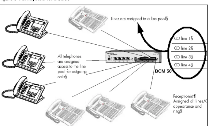
PBX system
This setup is for larger offices which have fewer CO lines than telephones. In this case the lines are pooled, and the line pool access is assigned to all DNs. There may also be a designated attendant with a telephone that has all lines individually assigned.
Figure 2 PBX system for BCM450
The following figure shows a PBX system for the BCM50. BCM 450
Figure 3 PBX system for BCM50
Incoming calls
1 A call comes in on a line.
2 The receptionist answers the call and finds out who the call is for. 3 The receptionist transfers the call to a specific telephone (DN). 4 The person can pick up the call at that DN only.
Outgoing calls
1 User selects the intercom button or dials a line pool access code, which selects a line in the line pool.
2 The user dials the outgoing telephone number.
DID system
This setup allows you to assign a dedicated phone number to each telephone. The CO assigns a list of available numbers for each DID (Direct Inward Dial) line. You can change your DN range to match these numbers, and you use target lines to match each number with a DN.
The following figure shows a DID system for the BCM450. BCM 50
Figure 4 DID system for BCM 450
The foloowing figure shows a DID system for BCM50.
Figure 5 DID system for BCM 50
Target line mapped to DN (4005)
Target line mapped to DN (4006)
Target line mapped to
DN (4007) Target line mapped to
DN (4008)
CO DID line i.e. 769
with range of call numbers (4005 to 4020)
Target line mapped to DN (4005)
Target line mapped to DN (4006)
Target line mapped to
DN (4007) Target line mapped to
Incoming calls
1 DID trunks are assigned to be auto-answer.
Attention: PRI lines are automatically set to auto-answer.
2 All DNs are assigned target lines.
3 A caller dials a system code and a DN. In the example shown above, it might be 769-4006.
4 The call comes into the trunk, which answers and maps the call on the target line assigned to the matching received digits.
5 The DN assigned to that target line rings.
You can assign unanswered or busy telephones to Call Forward to another DN, such as a designated attendant or a voice-mail system.
Basic telephony routing
In a basic configuration, simple access codes (for example Line Pool Codes) are used to access the PSTN network.
In a more complex configuration, more advanced destination codes are required to access multiple PSTNs, private network resources, and remote nodes. Access to these resources enables advanced features, such as tandem routing.
Tandem calling to a remote PSTN
A system connected to a private network that uses dedicated circuits or VoIP circuits can allow a user to dial directly to many other users, on different nodes, using a coordinating dialing plan.
Using a private network saves on toll charges, and local charges, as fewer PSTN accesses are required for internal and external calling. Several nodes located on one site initiate their external local calls to a centralized BCM having a T1 or E1 termination to the PSTN. This type of configuration avoids multiple PSTN terminations at other local nodes.
The same tandeming concepts can be applied to inbound calls. DID numbers dialed from the PSTN can be processed and tandem routed out of the centralized system to the localized remote nodes. For more information see, Creating tandem private networks (page 35).
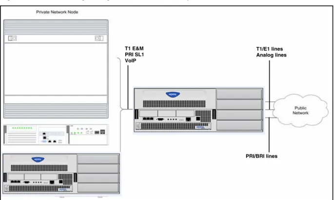
The following figure shows three types of callers. Each type of caller has a specific method of accessing the other two BCM450 systems.
Figure 6 Tandem dialing through a BCM450 to/from a private network
The following figure shows three types of callers. Each type of caller has a specific method of accessing the other two BCM50 systems.
T1 E&M PRI SL1 VoIP T1/E1 lines Analog lines PRI/BRI lines
Figure 7 Tandem dialing through a BCM50 to/from a private network
Callers using BCM
These callers can
• call directly to a specific telephone
• select an outgoing line to access a private network
• select an outgoing line to access features that are available on the private network
• select an outgoing central office line to access the public network • use all of the BCM features
Callers in the public network
These callers use the public lines to • call directly to one or more BCM DNs
• call into BCM and select an outgoing TIE line to access a private network • call into BCM and select an outgoing central office line to access the public
network
• call into BCM and use remote features T1 E&M PRI SL1 VoIP T1/E1 lines Analog lines PRI/BRI lines
Callers in the private network node
These callers use the private lines to • call directly to one or more BCM DNs
• call into BCM and select an outgoing TIE line to access other nodes in a private network
• call into BCM and select an outgoing central office line to access the public network
• call into BCM and use remote features
System numbering and dialing plans
All systems on a private network must coordinate dialing plans, to ensure that calls get directed to the correct network node. As well, routing becomes more complex, especially if the system is not an end node and must be configured to relay calls to nodes not directly connected to the system. The type of dialing plan supported by the network determines whether each node also requires unique DNs.
Private network parameters
The following sections provide an overview of the system values that affect private networking.
• Private networking protocols (page 28) • Keycode requirements (page 29)
• Remote access to the network (page 29) • Lines used for networking (page 29) • Types of private networks (page 30)
Private networking protocols
The BCM supports the following protocols for private networking: • PRI: ETSI QSIG, Nortel Voice Networking (MCDN)
• DPNSS
• BRI: ETSI QSIG • T1: E&M
• VoIP trunks (with optional MDCN)
BCM systems can be networked together using T-1, PRI or VoIP trunks. PRI SL-1 lines and VoIP trunks also offer the opportunity to use the MCDN protocol, which provides enhanced trunking features and end-to-end user identification. If a Meridian 1 is part of the MCDN network, the network can also provide centralized voice mail and auto attendant off the Meridian.
Attention: MCDN networking requires all nodes on the network to use a common Universal Dialing Plan (UDP) or a Coordinated Dialing Plan (CDP).
Keycode requirements
Keycodes are required to activate the protocols that are used to create private networking, including:
• VoIP Gateway keycodes
• an MCDN, DPNSS, or Q. Sig keycode, if you want to use a networking protocol between the systems
You must purchase and install these keycodes before you can create any of the networks described in this chapter. Consult with your Nortel distributor to ensure you order the correct keycodes for the type of network you want to create.
Remote access to the network
Authorized users can access TIE lines, central office lines, and features from outside the system. Remote users accessing a private network configured over a large geographical area can avoid toll charges.
Attention: You cannot program a DISA DN or Auto DN to a VoIP trunk, as they act as auto-answer trunks from one private network to the next. However, you can configure VoIP line pools with remote access packages so that callers can access telephones or the local PSTN on remote nodes on a tandemed network that use VoIP trunks between systems.
Lines used for networking
External (trunk) lines provide the physical connection between BCM and other systems in a private or public network.
The BCM50 numbers physical lines from 061 to 124. Default numbering depends on the type and connection to the BCM50 (EXP1 - EXP2)
VoIP trunks: Although a VoIP gateway does not use physical lines, it is easier to think of them that way. BCM450 supports a dynamically configurable number of IP trunk line numbers, from 0 to 130. In the BCM50, lines 001 to 012 are used for VoIP trunk functionality.
BCM networking configurations that use PRI and T1 lines, require specific DTM modules.
• DTMs configured for PRI are used for incoming and outgoing calls (two-way DID). Incoming calls are routed directly to a BCM DN that has a properly configured and assigned target line. All outgoing calls made through PRI, are initiated using the destination codes.
• DTMs configured for T1/E1 can have digital lines configured as Groundstart, E&M, Loop, or DID.
Target lines are virtual communication paths between trunks and telephones on the BCM system. They are incoming lines only, and cannot be selected for outgoing calls or networking applications. With target lines, you can
concentrate incoming calls on fewer trunks. This type of concentration is an advantage of DID lines. BCM target lines allow you to direct each DID number to one or more telephones. VoIP trunks also require target lines to direct incoming traffic.
In BCM450, there is a maximum of 639 target lines. In BCM 50, there is a maximum of 176 target lines.
Telephones can be configured to have an appearance of analog lines or multiple appearances of target lines.
Attention: PRI channels cannot be assigned as line appearances. PRI B-channels, or “trunks”, can only be configured into PRI line pools for inbound routing through target lines with receive digits or outbound routing through destination codes.
Types of private networks
There are several ways you can create private networks. Configuration can be based on such things as cost of trunks, proximity of network nodes, size of the private network, and business requirements for communications.
VoIP-based networking also requires an understanding of IP features such as codecs, jitter buffers, Quality of Service (QoS) function, and silence
compression.
The services provided within networks is based on the type of trunks and the protocols assigned to the trunks. All trunks within the network should be running the same protocols, to provide a technically sound and stable network.
The following links are procedures to set up basic networks to advanced networks, using the support protocols within BCM:
• Routing-based networks using T1 E&M lines (page 31) • PRI networking using Call-by-Call services (page 33)
• PRI SL-1/Q.Sig/DPNSS and VoIP trunk networking (page 34)
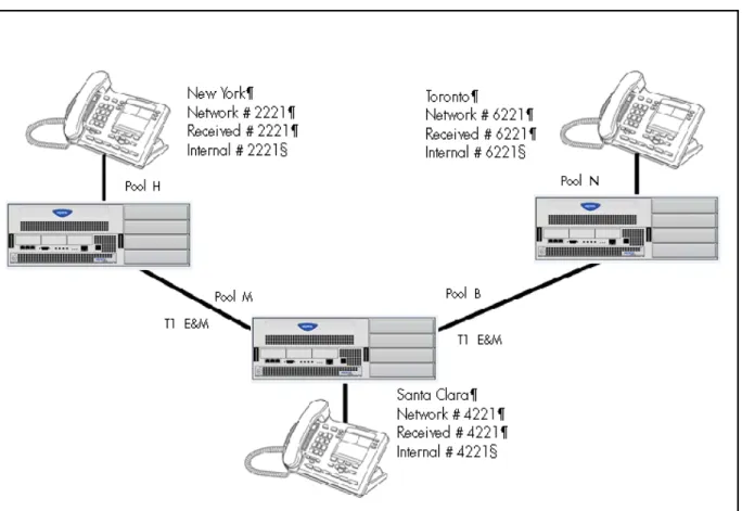
Routing-based networks using T1 E&M lines
By properly planning and programming routing tables and destination codes, an installer can create a dialing plan where T1 E&M lines between BCM systems are available to other systems in the network.
The following figure shows a network of three BCM450 systems. Two remote systems connect to a central system.
Figure 8 Dialing plan for T1 E&M routing network of BCM450s
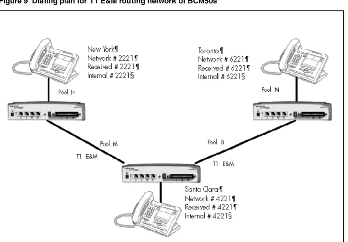
The following figure shows a network of three BCM50 systems. Two remote systems connect to a central system.
Figure 9 Dialing plan for T1 E&M routing network of BCM50s
Each system must be running BCM software. Each system must be equipped with target lines and a DTM with at least one T1 E&M line.
The call appears on the auto answer line on the BCM in Santa Clara as 6-221. Because 6 is programmed as a destination code for Toronto on the Santa Clara system, another call is placed using route 002 from Santa Clara to Toronto. At the Toronto system, the digits 6-221 are interpreted as a target line Private received number. The call now alerts at DN 6221 in Toronto.
Attention: Network calls that use routes are subject to any restriction filters in effect. If the telephone used to make a network call has an appearance of a line used by the route, the call will move from the intercom button to the Line button. The telephone used to make a network call must have access to the line pool used by the route. Network calls are external calls, even though they are dialed as if they were internal calls. Only the features and
capabilities available to external calls can be used.When programming a button to dial a Network number automatically (autodial), network calls must be treated as external numbers, even though they resemble internal
telephone numbers. Routes generally define the path between your BCM switch and another switch in your network, not other individual telephones on that switch.
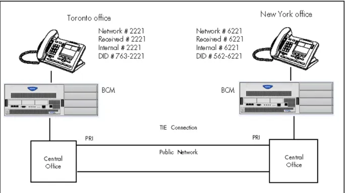
PRI networking using Call-by-Call services
The example shown in the following figure highlights the use of PRI Call-by-Call services. It shows two offices of a company, one in New York and one in Toronto. Each office is equipped with a BCM450 system and a PRI line. Each office has to handle incoming and outgoing calls to the public network. In addition, employees at each office often have to call colleagues in the other office. For more information, see Configuring call-by-call services and PRI lines (page 209).
Figure 10 PRI networking using Call-by-Call Services on BCM 450
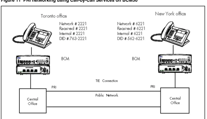
The example shown in the following figure shows two offices, where each office is equipped with a BCM50 system and a PRI line.
Figure 11 PRI networking using Call-by-Call Services on BCM50
To reduce long distance costs, and to allow for a coordinated dialing plan between the offices, private lines are used to handle inter-office traffic.
If call-by-call services were not used, each BCM system might have to be equipped with the following trunks:
• 12 T1 DID lines needed to handle peak incoming call traffic • eight T1 E&M lines needed to handle inter-office calls • eight lines needed to handle outgoing public calls
PRI SL-1/Q.Sig/DPNSS and VoIP trunk networking
You can use PRI SL-1 trunks and VoIP trunks to create private networks between BCM systems or between BCM systems and larger call servers such as Meridian 1, Succession 1000/M, DMS-100/ 250 and CSE.
ETSI-QSIG and DPNSS private networking is configured very similarly, although network features may be supported slightly differently due to local line and network requirements.
If the MCDN protocol is added to this type of private network, the network provides additional network management features, as well as allowing centralized voice mail features to be available to all nodes on the network.
The following topics describe the different aspects of SL-1 and MCDN private networking.
• System dialing plans (page 35)
• Creating tandem private networks (page 35)
• Understanding Nortel Voice Networking (MCDN) network features (page 37)
• Networking with ETSI QSIG (international systems only) (page 43) • Private networking with DPNSS (international only) (page 53)
The type of network you require depends on the equipment in the network, and how you want to use the network.
With MCDN, you can tie a set of BCM systems together with PRI SL-1 (MCDN)/ETSI-QSIG, DPNSS, or VoIP trunks to create a tandem network. This type of network provides the additional advantage of providing private line access to local PSTNs for all the nodes on the network.
Attention: A keycode is required to use the Nortel Voice Networking functionality, which is referred to as SL-1 in Business Element Manager.
System dialing plans
Both of these types of networks require similar setups for dialing plans and routing. Each node must have a way to route external calls to the adjacent node or nodes. To do this, all nodes must have the same Private DN lengths.
You use routing and a private dialing plan to control calls over the network. Each example in this section describes the routing configurations that are required to support calls over the network.
Depending on the type of dialing plan you choose, each node must also have a unique location or steering code so the calls can be correctly routed through the nodes of the network. MCDN networks also require a Private Network ID, which is supplied by the Meridian network administrator to define how the Meridian system identifies each node.
Creating tandem private networks
You can tie a number of BCM systems together with SL-1 lines. This tandem network provides you with the benefits of end-to-end name display and toll-free calling over the SL-1 private link. Each BCM system becomes a node in the network. In this type of network, you must ensure that each BCM system, known as a node of the network, is set up to route calls internally as well as to other nodes on the system. This means each node must have a route to the
immediately adjacent node, and the correct codes to distribute the called numbers. Each node must have a unique identification number, which is determined by the type of dialing plan chosen for the network.
Also, you can save costs by having a public network connection to only one or two nodes, and routing external calls from other nodes out through the local PSTN, thus avoiding toll charges for single calls.
Attention: You can also use VoIP trunks between some or all of the nodes. The setup is the same, except that you need to create gateway records for each end of the trunk, and routing tables to accommodate the gateway codes, or you can configure a gatekeeper. For more information, see Nortel Business Communications Manager 5.0 Planning and Engineering
(NN40170-200).
Routing for tandem networks
In tandem networks, each node needs to know how to route calls that do not terminate locally. To do this, you set up routes for each connecting node by defining destination codes for each route.
If the node is also connected to the public network, the usual routing is required for that connection.
The following tables show the routing tables for Node A and Node C for external and internal terminating calls.
Attention: The PRI and VoIP trunks are en bloc dialing lines, so all dialed digits are collected before being dialed out.
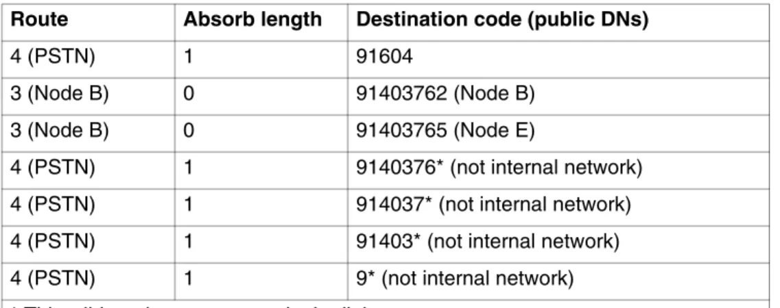
Table 1 Node A destination code table, external termination Route Absorb length Destination code (public DNs)
4 (PSTN) 1 91604
3 (Node B) 0 91403762 (Node B) 3 (Node B) 0 91403765 (Node E)
4 (PSTN) 1 9140376* (not internal network) 4 (PSTN) 1 914037* (not internal network) 4 (PSTN) 1 91403* (not internal network) 4 (PSTN) 1 9* (not internal network) * This wild card represents a single digit.
Understanding Nortel Voice Networking (MCDN) network features
When you connect your BCM systems through PRI-SL-1/ETSI QSIG/DPNSS or VoIP trunks, and activate the MCDN protocol, your network provides a number of network call features. You can use this protocol to network other BCM systems, such as the tandem system shown in Creating tandem private networks (page 35), Norstar systems, Meridian 1 systems, Succession systems, DMS-100 systems or CSE systems.Table 2 Node A destination code table, internal termination Route Absorb length Destination code (public DNs)
3 (Node B) 0 392 (Node B)
3 (Node B) 0 395 (Node E)
5 (Node C) 0 393 (Node C) 5 (Node C) 0 394 (Node D) 5 (Node C) 0 396 (Node F)
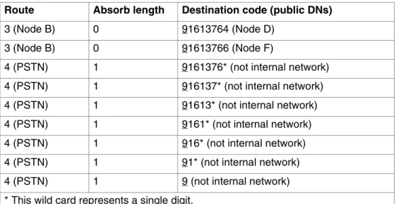
Table 3 Node C destination code table, external termination Route Absorb length Destination code (public DNs)
3 (Node B) 0 91613764 (Node D) 3 (Node B) 0 91613766 (Node F)
4 (PSTN) 1 9161376* (not internal network) 4 (PSTN) 1 916137* (not internal network) 4 (PSTN) 1 91613* (not internal network) 4 (PSTN) 1 9161* (not internal network) 4 (PSTN) 1 916* (not internal network) 4 (PSTN) 1 91* (not internal network) 4 (PSTN) 1 9 (not internal network) * This wild card represents a single digit.
Table 4 Node C destination code table, internal termination Route Absorb length Destination code (public DNs)
3 (Node D) 0 394 (Node D)
3 (Node D) 0 396 (Node F)
5 (Node A) 0 391 (Node A) 5 (Node A) 0 392 (Node B) 5 (Node A) 0 395 (Node E)
The following sections describe the MCDN features that are provided by all SL-1/VoIP networks where MCDN is active. The features affect call redirection and trunking functions.
Centralized messaging
• Network Call Redirection Information (page 38) Centralize trunking
• ISDN Call Connection Limitation (page 39) • Trunk Route Optimization (page 41)
Network Call Redirection Information
Network Call Redirection Information (NCRI) builds on the following BCM features:
• External Call Forward • Call Transfer
• Call Forward
NCRI adds the ability to redirect a call across an MCDN network using Call Forward (All Calls, No Answer, Busy) and Call Transfer features. The call destination also receives the necessary redirection information. This feature allows the system to automatically redirect calls from within a BCM system to the mail system, such as Meridian Mail, which resides outside the BCM system on the Meridian 1.
The following figure shows an example where user A calls user B on the same BCM450. If user B is busy or not answering, the call automatically gets transferred to a Meridian Mail number (user C) across an MCDN link between the BCM450 system and the Meridian 1 system where the mailboxes are set up.
Figure 12 Network call redirection path on BCM450
The following figure shows an example where user A calls user B on the same BCM50. If user B is busy or not answering, the call automatically gets transferred to a Meridian Mail number (user C) across an MCDN link between the BCM50 system and the Meridian 1 system where the mailboxes are set up.
Figure 13 Network call redirection path on BCM50
ISDN Call Connection Limitation
The ICCL (ISDN Call Connection Limitation) feature piggybacks on the call initiation request and acts as a check at transit PBX points to prevent misconfigured routes or calls with errors from blocking channels.
This feature adds a transit/tandem counter to a call setup message. This counter is compared at each transit PBX with a value programmed into the transit PBX, in a range from 0 to 31. If the call setup counter is higher than the PBX value, the call will be blocked at the PBX system and cleared back to the network. This prevents calls from creating loops that tie up lines.
The following figure illuustrates how a call might loop through a network if the BCM450 is not set up with ICCL.
Figure 14 Call loop on BCM450 without ICCL
The figure figure demonstrates how a call might loop through a network if the BCM50 is not set up with ICCL.
Figure 15 Call loop on BCM50 without ICCL
Trunk Route Optimization
Trunk Route Optimization (TRO) finds the most direct route through the network to send a call between nodes. This function occurs during the initial alerting phase of a call.
To set BCM configurations:
• Select Configuration > Dialing Plan > Private Network, and select the check box beside TRO in the MCDN pane.
• Configure call routing for all optimal routes.
• Configure call forward (All Calls, No Answer, Busy) or Selective Line Redirection to use the optimal routes.
This feature avoids the following situation: A call originating from a BCM system may be networked to a Meridian system, which, in turn, is networked to another Meridian system, which is the destination for the call. If the call routes through the first Meridian (M1) to reach the second Meridian (M2), two trunks are required for the call. An optimal choice is a straight connection to M2. This finds these connections and overrides the less-efficient setup.
The following figure shows two call paths. The first route, through the Meridian, demonstrates how a call might route if TRO is not active. The second route, that bypasses the Meridian, demonstrates how TRO selects the optimum routing for a call.
Figure 16 Call paths from BCM 450 with and without TRO
The following figure shows two call paths. The first route, through the Meridian, demonstrates how a call might route if TRO is not active. The second route, that bypasses the Meridian, demonstrates how TRO selects the optimum routing for a call.
Networking with ETSI QSIG (international systems only)
ETSI QSIG is the European standard signaling protocol for multi-vendor peer-to-peer communications between PBX systems and/or central offices (see ETSI Euro network services (page 44)).
The figure ETSI QSIG networking using BCM450 (page 43) illustrates an ETSI QSIG network using BCM450. Note that this is exactly the same setup as that shown in the MCDN section for North America. The hardware programming for ETSI QSIG is described in Hardware programming for branch offices (page 44). All other configurations are the same as those shown in the MCDN section for North America.
Figure 18 ETSI QSIG networking using BCM450
The following figure illustrates an ETSI QSIG network using BCM50. Note that this is exactly the same setup as that shown in the MCDN section for North America. The hardware programming for ETSI QSIG is described in Hardware programming for branch offices (page 44). All other configurations are the same as those shown in the MCDN section for North America.
Network #2221 Received #2221 Internal #2221 Network #6221 Received #6221 Internal #6221
BCM West End Branch BCM East End Branch
Central Office DN #4221 PRI/BRI ETSI QSIG PRI/BRI ETSI QSIG PBX
Figure 19 ETSI QSIG networking using BCM50
The following table lists the settings for some of the hardware parameters for ETSI QSIG networking example shown above.
ETSI Euro network services
If your system has ETSI ISDN BRI/PRI lines, you can activate the malicious call identification (MCID) and Network Diversion features. Advice of charge-end call (AOCE) is active if your service provider has activated that service on the line.
Table 5 Hardware programming for branch offices
West-end office East-end office
Hardware programming
DTM/BRIM PRI/BRI Hardware programming
DTM/BRIM PRI/BRI Protocol ETSI QSIG Protocol ETSI QSIG BchanSeq Ascend (PRI
only)
BchanSeq Ascend (PRI only)
ClockSrc Primary ClockSrc Primary
Network #2221 Received #2221 Internal #2221 Network #6221 Received #6221 Internal #6221
BCM West End Branch BCM East End Branch
Central Office DN #4221 PRI/BRI ETSI QSIG PRI/BRI ETSI QSIG PBX
When the features are activated, users can • display a call charge
• redirect calls over the ETSI ISDN BRI/PRI line to the outside network • tag malicious calls
Advice of Charge-End of Call (AOCE) — AOCE is a supplementary service available from your service provider on ETSI ISDN BRI/PRI links. This feature allows the BCM user to view the charges for an outgoing call after the call completes. This information is also reported to the Call Detail Reporting Application. The information can be provided in currency or charging units, depending on how the feature is set up by your service provider.
To invoke the feature, the user presses FEATURE 818.
DPNSS 1 services
The Digital Private Network Signaling System (DPNSS 1) is a networking protocol enhancement that extends the private networking capabilities of existing BCM systems. It is designed to offer greater centralized functionality for operators, giving them access to BCM features over multiple combined networks.
Attention: The DPNSS feature is dependent on which region loaded on your system at startup and that a software keycode was entered to enable the feature.
For more information, see
• DPNSS 1 capabilities (page 46) • DPNSS 1 features (page 47)
• Private networking with DPNSS (international only) (page 53) DPNSS 1 allows a BCM local node, acting as a terminating node, to communicate with other PBXs over the network. For example, corporate offices separated geographically can be linked over DPNSS 1 to other BCM nodes, bypassing the restrictions of the PSTNs to which they may be connected. Connected BCM nodes can therefore function like a private network, with all features of BCM accessible.
Attention: BCM DPNSS 1 works as a terminating node only. BCM-to-BCM
You can use DPNSS 1 features on any BCM telephone. On most BCM telephones, you must use specific keys and/or enter a number code to access the features.
DPNSS 1 capabilities
A single BCM node, acting as a terminating node on the network, supports the following capabilities over DPNSS 1 lines:
• Direct Dial Inward (DDI) for incoming calls.
• Originating Line Identification (OLI) for incoming and outgoing calls: — For incoming calls, the Calling Line Identification (CLI/CLID)
information is displayed to the user on telephones with line display. This must be configured in programming.
— For outgoing calls, the directory number of the originating party is sent out as OLI.
• Terminal Line Identification (TLI) for incoming and outgoing calls. Referred to as Called Line Identification.
• Selective Line Redirect (SLR) and External Call Forward (ECF) implemented on calls between DPNSS 1, and BRI/PRI, DASS2, and analog lines.
• These remote access features are supported on DPNSS: DDI, line pool access code, destination codes and remote page feature codes.
Keycodes are required to enable DPNSS 1.
DPNSS to Embark connections
DPNSS lines connected to an Embark switch perform call redirection/ diversion using the Call Forward feature to create a tandem link back to the switch. Since this is different from other switches, you must select the type of switch DPNSS will be connecting to when you do module programming.
Before you program Call Forwarding, ensure that
• Both real channels and virtual channels are provisioned.
• Destination or line pool codes are programmed for the DPNSS to Embark link.
Also, during programming for Call Forward No Answer and Call Forward on Busy, when you enter the Forward to: digits, the system does a validation check with the switch on the number. (Configuration > Telephony > Sets > Active Sets > Line Access)
DPNSS 1 features
DPNSS features (page 47) lists available features that can be programmed over DPNSS lines:
The following parameters can be configured for DPNNS 1 lines: • Line type • Prime set • CLID set • Auto privacy • Answer mode • Auxiliary ringer • Full autohold
Some features are transparent to the user, but must be programmed to be activated. Others are available for end-user programming at the telephone. Details about these features are given in the following sections.
Three-party service
Three Party Service is a DPNSS 1 feature for BCM that is similar to the BCM Conference feature.
The Three Party Service allows a user, usually an operator, to establish a three-party conference by calling two other parties from one telephone. Once the connection is made, the controlling party can hang up, leaving the other two connected. The controlling party can even put one party on hold, and talk to the other party.
Table 6 DPNSS features
Feature BCM450 BCM50
Three-party service supported supported Conference calls supported not supported Diversion feature supported supported Redirection feature supported supported Executive intrusion supported supported
Call offer supported supported
Route optimization supported supported Loop avoidance supported supported Message Waiting Indication not supported supported
Attention: BCM does not support Hold over the DPNSS link itself. This means that the conferenced party on the distant end of the network cannot place a Three Party Service call on Hold.
This feature is designed to allow operators to assist in the connection of calls from one main location.
Conference calls
To initiate or disconnect from a conference call on a BCM system over DPNSS 1, use the procedure described in the Nortel Business Communications Manager 5.0 Configuration— Devices (NN40170-500).
Attention: Three Party Service is supported on model 7000 telephones, but in a receive-only fashion. These telephone types cannot initiate Three Party Service. For more information about these telephone types, see the Nortel Business Communications Manager 5.0 Installation— Devices (NN40170-304) (model 7000 phones, supported in Europe only).
Diversion feature
Diversion is a DPNSS 1 feature for BCM that allows users to forward their calls to a third party on the DPNSS 1 network. This feature is similar to Call Forward on BCM but takes advantage of the broader capabilities of DPNSS.
There are five variations of Diversion: Call Diversion Immediate, Call Diversion On Busy, Call Diversion On No Reply, Bypass Call Diversion, and Follow-me Diversion. These variations are described below:
• Diversion Immediate diverts all calls to an alternate telephone. This function is programmed by the user at their telephone.
• Diversion On Busy diverts all calls to an alternate telephone when a telephone is busy. You can program this feature in the Business Element Manager.
• Diversion On No Reply diverts calls that go unanswered after a specified amount of time. You can program this feature in the Business Element Manager.
• Bypass Call Diversion overrides all call forward features active on a telephone over a DPNSS line. An incoming call to the telephone will not be forwarded; instead, the telephone will continue to ring as if call forward were not active. This feature is used to force a call to be answered at that location. Bypass Call Diversion is a receive-only feature on BCM and cannot be used from a BCM telephone.
• Follow-me Diversion is also a receive-only feature. It allows the call-forwarded destination to remotely change the BCM call-forwarding
programming (Call Forward All Calls [CFAC] feature) to a different telephone.
Attention: BCM CFAC must be active, and the destination set/PBX system must support the feature.
For example, user A forwards all calls to telephone B, a temporary office. Later, user A moves on to location C. The user does not have to be at telephone A to forward calls to location C. Using telephone B and Follow-me Diversion, the user can forward calls from A to location C.
Follow-me diversion can be cancelled from the forwarded location.
• Diversion on Busy and Diversion on No Reply cannot be cancelled from the forwarded telephone. These are programmable only by an installer and not by the user.
• If multiple telephones are programmed to take a call, the first telephone to respond will act. All other telephones responding are ignored.
Therefore, if the first telephone to respond has Diversion enabled, this feature will be invoked.
For restrictions by telephone type
• all variations supported on BCM digital and IP telephones • ATA2/ASM8+—all variations supported on an ATA
• ISDN—all variations supported on ISDN telephones, except Diversion on Busy and CFWD Busy
For diversion, set Diversion for DPNSS in the same way as Call Forward. You will need to enter the end DN when prompted. You may also need to include the DPNSS 1 routing number.
Redirection feature
Redirection is a DPNSS 1 feature similar to BCM Transfer Callback. With Redirection, a call awaiting connection, or reconnection, is redirected by the originating party to an alternate destination after a time-out period. Failed calls can also be redirected. Priority calls are not redirected.
Attention: The address to redirect depends on the history of the call. Calls that have been transferred are redirected to the party that transferred them. In all other cases, the address to redirect is the one registered at the PBX system originating the redirection.
Attention: BCM does not support the redirection of BCM-originated calls, even over DPNSS 1.
The Diversion on No Reply feature takes precedence over Redirection.
For restrictions by telephone type
• For telephones with a single line display, the number key (#) acts as MORE
and the star key (*) acts as VIEW
• ISDN—all variations supported on ISDN telephones
For setting redirection, the timer used for the network Callback feature is also used for redirection.
Executive intrusion
Executive Intrusion (EI) is a DPNSS 1 feature that allows an operator, or other calling party, to intrude on a line when it is busy. An example of the use of this feature is to make an important announcement when the recipient is on another call.
EI is similar in functionality to BCM Priority Call, but it is a receive-only feature on BCM telephones. EI cannot be initiated from a BCM telephone. The person using this feature must be on another PBX system on the DPNSS 1 network.
When EI is used to intrude on a call in progress, a three-way connection is established between the originating party and the two parties on the call. The result is very much like a conference call. When one of the three parties clears the line, the other two remain connected, and EI is terminated.
For restrictions by telephone type • ATA2/ASM8+—supported • ISDN—not supported
The telephone receiving the intrusion displays Intrusion Call. A warning indication tone will sound after intrusion has taken place, and the standard conference call tone will sound every 20 seconds.
For intrusion levels, whether a telephone accepts or rejects an Executive Intrusion request depends on the level of intrusion protection programmed. Each telephone (DN) has an Intrusion Capability Level (ICL) and four Intrusion Protection Levels (IPL).
When the ICL of the intruding telephone is higher than the IPLs of both telephones on the active call, EI occurs. Nortel recommends that you set the IPLs of most BCM telephones to the default of None, or Low or Medium.
Intrusion levels are described as follows:
• ICL: determines the ability of the attendant to intrude. As long as the ICL is higher than the IPL of the wanted party, EI is allowed. Because EI is a receive-only feature, the ICL cannot beset on BCM.
• IPL: determines the ability of the attendant to refuse intrusion. If the IPL is lower than the ICL of the originating party, EI is allowed. For general purposes setting the IPL to None, Low or Medium is recommended, unless intrusion is not wanted.
Call Offer
Call Offer over DPNSS 1 allows a calling party to indicate to the wanted party that there is an incoming call available, even though there is no answer button available to present the call on the telephone. The intended recipient can ignore, accept, or decline the offered call. Call Offer is useful in increasing the call-coverage capability of a BCM system, and helps to lift the network processing load. It is a receive-only capability on BCM; incoming calls are initiated at another PBX system on the DPNSS 1 network.
An example of Call Offer in use is an operator or attendant who has a number of calls coming in at once. The operator can call offer one call and move to the next without waiting for the first call to be answered.
When a Call Offer is made by the originating exchange, the target telephone displays a message, and a tone is heard. When an offered call arrives on telephones with line display, the user sees XX...X wtng if the calling party ID is available and CLID is enabled. If CLID is not available or CLID is disabled, Line XXX waiting appears (the line name associated with the call). If there are more than 11 digits in the incoming number, only the last 10 will display.
If Call Queuing is programmed for the system, the display shows Release Line XXX.
This is the line name of the highest-priority queued call if it is an offered call.
Restrictions by telephone type include
• model 7000 telephone — associated LED or LCD flashes, and a tone is heard (model 7000 phones, supported in Europe only.)
• ATA2/ASM8+—Call Offer is supported as a Camp On feature, and a tone is heard
• ISDN—not supported
Note the following general conditions and restrictions:
• Clear the DND on busy check box (DN ##/Capabilities) for a telephone to accept Call Offer.
• If CF on busy is programmed for the telephone, Call Offer is not accepted. • The target line for the telephone must be set to: If busy: busy tone, which
is the default.
• Call Offer does not work if sent over Manual answer lines. It is recommended that the lines be left at the default: Auto.
For user actions, the party receiving a Call Offer has three choices:
• Ignore it. After a programmed time interval, the Offer request is removed. • Reject it. If the user activates Do Not Disturb on Busy (DND) when the Call Offer request is made, the request is removed from the telephone. The calling party is informed of the rejection.
Attention: A call cannot be offered to a telephone with DND active. The line indicator for external incoming calls still flashes.
• Accept it. The Offer is accepted by releasing the active call.
Attention: Forward on Busy takes priority over DND on Busy. Call Offer cannot be accepted by putting an active call on hold.
Route Optimization
Route Optimization is a DPNSS 1 feature for BCM that allows calls to follow the optimum route between two end PBXs. This allows efficient use of network resources.
Route Optimization is initiated by the system and is transparent to the user. However, the user may see a call switch from an appearance on the telephone to another appearance key or from an intercom button to the appearance key or vice versa. This occurs when BCM receives a Route Optimization request and initiates a new call to follow the optimal route.
If a telephone is active on a private line call, the Route Optimization call being established may go on a public line. This will cause a loss of privacy on that line.
Data calls are rejected by Route Optimization in order to ensure the data transmission is not affected.
Certain situations result in Route Optimization not taking place. For example, calls that are using Hold, Parking or Camp features do not undergo Route Optimization, and if a Route Optimization call undergoes Diversion, the Route Optimization is dropped.
When setting Route Optimization, System programming is not required when BCM is working as a terminating PBX system. However, BCM must have a private access code programmed that maps to a valid destination code or line pool code on DPNSS lines. Further, Allow Redirect must be selected.
Loop avoidance
Errors in the configuration of a network may make it possible for a call to be misrouted, and arrive at a PBX system through which it has already passed. This would continue, causing a loop which would eventually use up all of the available channels. The Loop Avoidance service permits counting of DPNSS 1 transit PBXs and rejecting a call when the count exceeds a predetermined limit.
Private networking with DPNSS (international only)
DPNSS supports the Universal Dialing Plan (UDP), an international standard for sending and receiving private numbers over networks. The UDP requires that a dialing number include the following:
• a Private Access Code, programmed into the system as part of the destination code table to prevent conflicts with the internal numbering system. (Access Codes)
• a Home Location Code (HLC) assigned to each PBX system, and configured as part of the destination code (a maximum of seven digits). For each HLC, a destination code must be programmed in the system. (Configuration > Telephony > Dialing Plan > Private Networking) • a Directory Number (DN) assigned to each extension as a line
appearance. The DN appears as the last string segment in a dialed number. In the number 244-1111, 1111 is the DN.
A typical Private Number, using a private access code and dialed from another site on the network, appears in the following table.
In this networking example, a private network is formed when several systems are connected through a Meridian 1 and a terminating BCM450 system. Each site has its own HLC and a range of DNs. The following figure illustrates this example.
The following table shows examples of the construction of numbers used when dialing within the example network. Note that 6 is the Private Access code.
Private Access Code + Home Location Code + Directory Number = Calling Party Number
Figure 20 DPNSS networking using BCM 450
The following figure illustrates this example using BCM50. Calling site LOC/HLC Calling party
number
Called site Dialling string Called party number Site A 244 244 1111 Site B 6 688 2222 668 2222 Site B 668 662 2222 Site D 6 848 2222 848 2222 Site C 848 2222 Site D 2229 2229 Site D 496 496 3333 Public DN 9 563 3245 563 3245 Private Network DPNSS DPNSS DPNSS DPNSS BCM Site B DN #2222 Loc #668 BCM Site D DN #2229 Extension 2222 Loc #848 BCM Site C DN #3333 Loc #496 Terminating BCM Site A DN #111 Loc #244 Meridian M1 Loc #563