An Introduction to
ATM Networks
by
An Introduction to
ATM Networks
To
Helen, Nick, and Mikey
Foreword
ATM networks was the subject of intense research and development from the late 1980s to the late 1990s. Currently, ATM is a mature networking technology and it is taught regularly in Universities and in short professional courses. This book was written with a view to be used as a text book in a second course on computer networks at the graduate level or senior undergraduate level. Also, it was written for networking engineers out in the field who would like to learn more about ATM networks. A pre-requisite for this book is basic knowledge of computer networking principles.
The book is organized into the following four parts:
Part One: Introduction and Background
Part Two: The ATM Architecture
Part Three: Deployment of ATM
Part Four: Signalling in ATM Networks.
Part One “Introduction and Background” contains a variety of topics which are part of the background necessary for understanding the material in this book. It consists of Chapters 1, 2, and 3. Chapter 1 contains a discussion of what caused the development of ATM networks, and a brief description of the various standards committees that feature prominently in the development of ATM networks. Chapter 2, gives a review of basic concepts of computer networks that are used in this book. This Chapter can be skipped by the knowledgeable reader. Chapter 3 is dedicated to frame relay, where we describe the motivation behind the development of frame relay and its basic features, the frame relay UNI, and congestion control. It is educationally constructive to understand how frame relay works since it is a very popular networking solution and it has many common features with ATM networks, such as, layer two switching, no error or flow control between two adjacent nodes, and similar congestion control schemes.
decision to use such a small packet. Then, we describe the structure of the header of the ATM cell, the ATM protocol stack, and the various ATM interfaces. We conclude this Chapter with a description of the physical layer that supports ATM networks and the various public and private interfaces. In Chapter 5, we describe the ATM adaptation layer. The purpose of this layer is to isolate higher protocol layers and applications from the specific characteristics of ATM. Four different ATM adaptation layers are described, namely ATM adaptation layers 1, 2, 3/4, and 5. Chapter 6 is dedicated to ATM switch architectures, and the following three different classes of ATM switch architectures are presented: space-division switches, shared memory switches, and shared medium switches. We describe various architectures that have been proposed within each of these three classes. Also, to give the reader a feel of a real-life switch, the architecture of a commercial switch is described. We conclude this Chapter by describing various algorithms for scheduling the transmission of cells out of an output port of an ATM switch. Finally, Chapter 7 deals with the interesting problem of congestion control in ATM networks. We first present the various parameters used to characterize ATM traffic, the various quality of service (QoS) parameters, and the standardized ATM classes. In the rest of the Chapter, we focus on the two classes of congestion control schemes, namely, the preventive and reactive congestion control. We introduce the preventive congestion control scheme, and we present various call admission control algorithms, the GCRA bandwidth enforcement algorithm, and cell discard policies. Finally, we present the available bit rate (ABR) scheme, a reactive congestion control scheme standardized by the ATM Forum.
being standardized by IETF under the name of multi-protocol label switching. Chapter 9 is dedicated to the asynchronous digital subscriber line (ADSL) technology which can be used in residential access networks to provide basic telephone services and access to the Internet. We describe the discrete multi-tone (DMT) technique used to transmit the information over the telephone twisted pair, the seven bearer channels, the fast and interleaved paths, and the ADSL super frame. Finally, we discuss architectures for accessing network service providers.
Part Four Signalling in ATM Networks focuses on the signalling protocols used to set-up a switched virtual connection (SVC). It consists of Chapters 10 and 11. In Chapter 10, we review the signalling protocols used to establish a point-to-point connection and a point-to-multipoint connection over the private UNI. The signalling protocol for establishing a point-to-point connection is described in ITU-T’s Q.2931 standard, and the signalling protocol for establishing a point-to-multipoint connection is described in ITU-T’s Q.2971 standard. We first describe a specialized ATM adaptation layer, known as the signalling AAL (SAAL), that is used by both protocols. Then, we discuss in detail the signalling messages and procedures used by Q.2931 and Q.2971. In Chapter 11, we examine the private network-network interface (PNNI) used to route a new call from an originating UNI to a destination UNI. PNNI consists of the PNNI routing protocol and the PNNI signalling protocol. We first describe the PNNI routing protocol in detail and then we briefly discuss the PNNI signalling protocol.
At the end of each Chapter there are problems given. Also, in some Chapters 6 and 7, there are three simulation projects designed to help the reader understand better some of the intricacies of ATM networks.
To develop a deeper understanding of ATM networks, one has to dig into the various documents produced by the standards bodies. Most of these documents are actually very readable! A list of standards which are relevant to the material in this book can be found at the end of the book.
Harry Perros
Contents
PART ONE: INTRODUCTION AND BACKGROUND
1. Introduction 3
1.1 The Asynchronous Transfer Mode (ATM) 3
1.2 Standards committees 5
Problems 11
2. Basic Concepts From Computer Networks 13
2.1 Communication networking techniques 13 2.2 The Open System Interconnection (OSI) Reference Model 16
2.3 Data link layer 17
2.4 The high data link control (HDLC) protocol 22 2.5 Synchronous time division multiplexing (TDM) 24
2.6 The logical link control (LLC) layer 27
2.7 Network access protocol X.25 29
2.8 The internet protocol (IP) 32
2.8.1 The IP header 32
2.8.2 IP addresses 34
2.8.3 ARP, RARO and ICMP 37
2.8.4 IP version 6 (IPv6) 38
Problems 38
3. Frame Relay 41
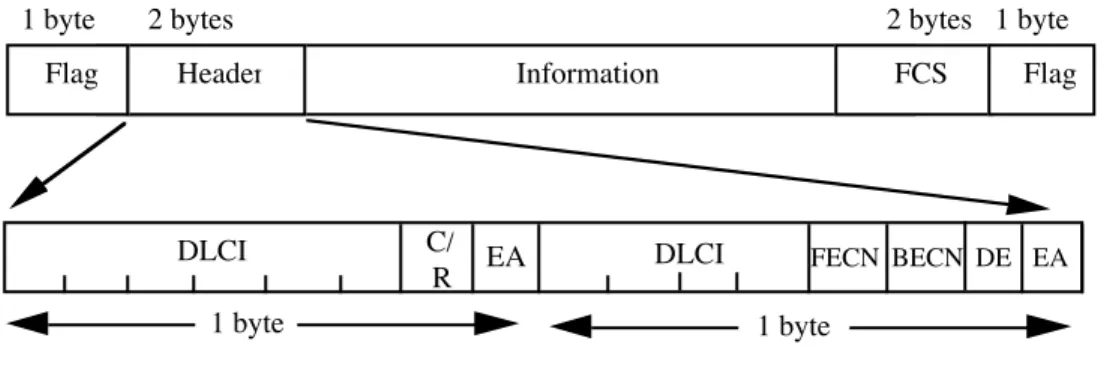
3.1 Motivation and basic features 41
3.2 The frame relay UNI 44
3.3 Congestion control 47
PART TWO: THE ATM ARCHITECTURE
4. Main Features of ATM Networks 55
4.1 Introduction 55
4.2 The structure of the header of the ATM cell 58
4.2.1 Generic flow control (GFC) 59
4.2.2 Virtual path identifier / virtual channel
identifier (VPI/VCI) 59
4.2.3 Payload type indicator (PTI) 62
4.2.4 Cell loss priority bit (CLP) 62
4.2.5 Header error control (HEC) 63
4.3 The ATM protocol stack 63
4.3.1 The physical layer 64
4.3.2 The ATM layer 64
4.3.3 The ATM adaptation layer 68
4.3.4 Higher level layers 68
4.4 ATM interfaces 68
4.5 The physical layer 71
4.5.1 The transmission convergence (TC) sublayer 71 4.5.2 The physical medium-dependent (PMD) sublayer 73 4.5.3 ATM physical layer interfaces 73
4.6 UTOPIA and WIRE 78
Problems 79
5. The ATM Adaptation Layer 81
5.1 Introduction 81
5.2 ATM Adaptation Layer 1 (AAL 1) 84
5.2.1 The AAL 1 SAR sublayer 84
5.2.2 The AAL 1 CS sublayer 85
5.3 ATM Adaptation Layer 2 (AAL 2) 88
5.4 ATM Adaptation Layer 3/4 (AAL 3/4) 92
Problems 97 6. ATM Switch Architectures 99
6.1 Introduction 99
6.2 Space-division switch architectures 102
6.2.1 The cross-bar switch 102
6.2.2 Banyan networks 105
6.2.3 Clos networks 113
6.2.4 Switch architectures with N2
disjoint paths 114 6.3 Shared memory ATM switch architectures 115 6.4 Shared medium ATM switch architectures 118 6.5 Non-blocking switches with output buffering 120
6.6 Multicasting in an ATM switch 121
6.7 Scheduling algorithms 123
6.8 The Lucent AC120 Switch 126
6.9 Performance evaluation of an ATM switch 129
Problems 130
A simulation model of an ATM multiplexer – Part 1 131 7. Congestion Control in ATM Network 133
7.1 Traffic characterization 134
7.1.1 Standardized traffic descriptors 136
7.1.2 Empirical models 137
7.1.3 Probabilisticmodels 138
7.2 Quality of service (QoS) parameters 141
7.3 ATM service categories 144
7.4 Congestion control 147
7.5 Preventive congestion control 147
7.6 Call admission control (CAC) 149
7.6.1 Equivalent bandwidth 151
7.6.2 The ATM block transfer (ABT) scheme 154
7.7 Bandwidth enforcement 158 7.7.1 The generic cell rate algorithm (GCRA) 160
7.7.2 Packet discard schemes 163
7.8 Reactive congestion control 164
7.8.1 Available bit rate (ABR) service 165
Problems 171
A simulation model of an ATM multiplexer – Part 2 171 Estimating the ATM traffic parameters of a video source 173
PART THREE: DEPLOYMENT OF ATM
8. Transporting IP Traffic Over ATM 177
8.1 Introduction 177
8.2 LAN emulation 179
8.3 Classical IP and ARP over ATM 183
8.3.1 ATMARP 184
8.3.2 IP multicasting over ATM 187
8.4 Next hop routing protocol (NHRP) 191
8.5 IP switching 194
8.6 Tag switching 198
8.7 Multi-protocol label switching (MPLS) 206
Problems 208
9. ADSL-Based Access Networks 211
9.1 Introduction 211
9.2 The ADSL technology 215
9.2.1 The discrete multi-tone (DMT) technique 217
9.2.2 Bearer channels 219
9.2.3 The ADSL super frame 220
9.3.2 The PPP terminated aggregation scheme 224
Problems 224
PART FOUR: SIGNALLING IN ATM NETWORKS
10. Signalling Over the UNI 229
10.1 Connection types 229
10.2 The signalling protocol stack 231
10.3 The signalling ATM adaptation layer (SAAL) 231
10.3.1 The SSCOP 232
10.3.2 Primitives 233
10.4 The signalling channel 236
10.5 ATM addressing 236
10.6 The format of the signalling message 239
10.7 The signalling protocol Q.2931 240
10.7.1 Information elements 241
10.7.2 Q.2931 messages 244
10.8 The signalling protocol Q.2971 247
10.9 Leaf initiated join (LIJ) capability 250
10.10 ATM anycast capability 252
Problems 253
11. The Private Network-Network Interface (PNNI) 255
11.1 Introduction 255
11.2 The PNNI routing protocol 256
11.2.1 The lowest-level peer groups 257
11.2.2 The next level peer groups 259
11.2.3 Uplinks 260
11.2.7 Address summarization 266
11.2.8 Level indicators 268
11.2.9 Path selection 268
11.3 The PNNI signalling protocol 269
Problems 271
List of standards 273
Glossary of abbreviations 277
PART ONE:
INTRODUCTION AND BACKGROUND
In Part One, we present several topics which are part of the background necessary for understanding ATM networks. It consists of Chapters 1, 2 and 3. Some of the material presented in these Chapters can be skipped by the knowledgeable reader.
Chapter 1: Introduction
In this Chapter we identify the various forces that gave rise to ATM networks, and describe some of the well-known standards bodies.
Chapter 2: Basic Concepts From Computer Networks
This Chapter gives a review of some basic concepts from computer networks that we will make use in this book.
Chapter 3: Frame Relay
CHAPTER 1
Introduction
In this Chapter, we introduce the Asynchronous Transfer Mode (ATM) networking technique, and discuss the forces that gave rise to it. Then, we describe some of the well-known national and international standards committees involved with the standardization process of networking equipment.
1.1 The Asynchronous Transfer Mode (ATM)
ATM is a technology that provides a single platform for the transmission of voice, video, and data at specified quality of service and at speeds varying from fractional T1, i.e., nX64 Kbps, to Gbps. Voice, data and video are currently transported by different networks. Voice is transported by the public telephone network, and data by a variety of packet-switched networks. Video is transported by networks based on coaxial cables, satellites, and radio waves, and to a limited extent, by packet-switched networks.
processing and remote printing of a newspaper. At the same time, optical fiber technology evolved very rapidly, and by the end of the 80s there was a lot of optical fiber installed. Optical fiber permitted high bandwidth and very low bit-error rate.
These technological developments coupled with the market needs for faster interconnectivity, gave rise to various high-speed wide-area networks and services, such as frame relay, Asynchronous Transfer Mode (ATM), and Switched Multimegabit Data Services (SMDS).
ATM was standardized by ITU-T in 1987. It is based on packet-switching and it is connection oriented. An ATM packet, known as a cell, is a small fixed-size packet with a payload of 48 bytes and a 5-byte header. The reason for using small packets was motivated mostly by arguments related to the transfer of voice over ATM.
Unlike IP networks, ATM has built-in mechanisms that permits it to provide different quality of service to different types of traffic. ATM was originally defined to run over high-speed links. For instance, in North America, the lowest envisioned speed was OC-3, which corresponds to about 155 Mbps. It should be noted that the fastest network in the late 80s was the FDDI which ran at 100 Mbps. However, as ATM became more widely accepted, it was also defined over slow links, such as fractional T1, that is, nX64 Kbps.
In the early 90s, ATM was poised to replace well-established local and wide area networks, such as Ethernet and IP networks. ATM was seen as a potential replacement for Ethernet because it ran faster and it also provided quality of service. We note that at that time Ethernet ran at 10 Mbps, but due to software bottlenecks its effective throughput was around 2 Mbps. Also, since ATM has its own addressing system and it can set-up and route connections through the network, it was seen as a potential foe of IP networks. In view of this, Ethernet and IP networks were declared by the ATM aficionados as “dead”!
service in IP networks. As a result, one frequently hears cries that it is the ATM technology that is now “dead”!
ATM is a mature networking technology and it is still the only networking technology that provides quality of service. ATM networks are used in a variety of environments. For instance, it is widely used in the backbone of Internet service providers (ISP) and in campus networks to carry Internet traffic. ATM wide area networks have also been deployed to provide point-to-point and point-to-multipoint video connections. Also, there are on going projects in telecommunication companies aiming at replacing the existing trunks used in the telephone network with an ATM network.
On a smaller scale, ATM is used to provide circuit emulation, a service that emulates a point-to-point T1/E1 circuit and a point-to-point fractional T1/E1 circuit over an ATM network. ATM is the preferred solution for ADSL-based residential access networks used to provide access to the Internet and basic telephone services over the phone line. Also, it is used in passive optical networks (PON) deployed in residential access networks.
We conclude this section by noting that arguments in favour and against existing and emerging new networking technologies will most likely continue for a long time. There is no argument, however, that these are indeed very exciting times as far as communication systems are concerned!
1.2 Standards committees
Standards allow vendors to develop equipment to a common set of specifications. Providers and end-users can also influence the standards so that the vendors’ equipment conform to certain characteristics. As a result of the standardization process, one can purchase equipment from different vendors without being bound to the offerings of a single vendor.
Several national and international standards bodies are involved with the standardization process in telecommunication, such as the International Telecommunication Union (ITU), the International Organization for Standardization
(ISO), the American National Standards Institute (ANSI), the Institute of Electrical and Electronics Engineering (IEEE), the Internet Engineering Task Force (IETF), the ATM Forum, and the Frame Relay Forum. The organizational structure of these standards bodies is described below.
The ITU-T and the ATM Forum are primarily responsible for the development of standards for ATM networks. ITU-T concentrates mainly on the development of standards for public ATM networks, whereas the ATM Forum concentrates on private networks. The ATM Forum was created because many vendors felt that the ITU-T standardization process was not moving fast enough, and also because there was an emerging need for standards for private ATM networks. In general, ITU-T tends to reflect the view of network operators and national administrations, whereas the ATM Forum tends to represent the users and the customer premises equipment (CPE) manufacturers. The two bodies compliment each other and work together to align their standards with each other.
The International Telecommunication Union (ITU)
ITU is a United Nations specialized agency whose job is to standardize international telecommunications. ITU consists of the following three main sections: the ITU Radiocommunications Sector (ITU-R), the ITU Telecommunications Standardization Sector (ITU-T), and the ITU Development Sector (ITU-D).
The ITU-T’s objective is the telecommunications standardization on a worldwide basis. This is achieved by studying technical, operating and traffic questions, and adopting recommendations on them. ITU-T was created in March 1993, and it replaced the former well-known standards committee International Telegraph and Telephone Consultative Committee, whose origins are over 100 years old. This committee was commonly referred to as CCITT, which are the initials of its name in French.
Contributions to standards are generated by companies, and they are first submitted to national technical coordination groups, resulting to national standards. These national coordinating bodies may also pass on contributions to regional organizations or directly to ITU-T, resulting in regional or world standards. ITU more recently started recommending and referencing standards adopted by the other groups, instead of re-writing them.
ITU-T is organized in 15 technical study groups. At present, more than 2500 recommendations (standards) or some 55,000 pages are in force. They are non-binding standards agreed by consensus in the technical study groups. Although, non-binding, they are generally complied with due to their high quality and also because they guarantee the inter-connectivity of networks, and enable telecommunications services to be provided on a worldwide scale.
ITU-T standards are published as recommendations, and they are organized into series. Each series of recommendations is referred to by a letter of the alphabet. Some of the well-known recommendations are the I, Q, and X. Recommendations I are related to integrated services digital networks. For instance, I.321 describes the B-ISDN protocol reference architecture, I.370 deals with congestion management in frame relay, and I.371 deals with congestion management in ATM networks. Recommendations Q are related to switching and signalling. For instance, Q.2931 describes the signalling procedures used to establish a point-to-point ATM switched virtual connection over the private UNI, and Q.2971 describes the signalling procedures used to establish a point-to-multipoint ATM switched virtual connection over the private UNI. Recommendations X are related to data networks and open system communication. For instance, X.700 describes the management framework for the OSI basic reference model, and X.25 deals with the interface between a DTE and a DCE terminal operating in a packet mode and connected to a public data networks by dedicated circuit.
The International Organization for Standardization (ISO)
view to facilitating the international exchange of goods and services, and to developing cooperation in the spheres of intellectual, scientific, technological and economic activity.
It is interesting to note, that the name ISO does not stand for the initials of the full title of this organization, which would have been IOS! In fact, ISO is a word derived from the Greek isos, which means “equal”. From “equal” to “standard”, was the line of thinking that led to the choice of ISO. In addition, the name ISO is used around the world to denote the organization, thus avoiding a plethora of acronyms resulting from the translation of “International Organization for Standards” into the different national languages of the ISO members, such as IOS in English, and OIN in French (from Organization International de Normalization).
ISO’s standards covers all technical fields. Well-known examples of ISO standards are: the ISO film speed code, the standardized format of telephone and banking cards, ISO 9000 which provides a framework for quality management and quality assurance, paper sizes, safety wire ropes, ISO metric screw threads, and the ISO international codes for country names, currencies and languages. In telecommunications, the open system interconnection (OSI) reference model (see Chapter 2) is a well-known ISO standard.
ISO has co-operated with the International Electronical Commission (IEC) to develop standards in computer networks. IEC emphasizes hardware while ISO emphasizes software. In 1987 the two groups formed the Joint Technical Committee 1
(JTC 1). This committee developed documents that became ISO and IEC standards in the area of information technology.
The American National Standards Institute (ANSI)
responsible for data communications. The main telecommunications standards organization within ANSI is the T1 secretariat, sponsored by the Exchange Carriers Standards Association. ANSI is focused on standards above the physical layer. Hardware oriented standards are the work of the Electronics Industries Association (EIA) in the US.
The Institute of Electrical and Electronics Engineering (IEEE)
IEEE is the largest technical professional society in the world, and it has been active in developing standards in the area of electrical engineering and computing through its
IEEE Standards Association (IEEE-SA). This is an international organization with a complete portfolio of standards. The IEEE-SA has two governing bodies: the Board of Governors, and the Standards Board. The Board of Governors is responsible for the policy, financial oversight, and strategic direction of the Association. The Standards Board has the charge to implement and manage the standards process, such as approving projects.
One of the most well-known IEEE standards body in the networking community is the LAN/MAN Standards Committee, or otherwise known as the IEEE project 802. They are responsible for several well-known standards, such as CSMA/CD, token bus, token ring, and the logical link control (LLC) layer.
The Internet Engineering Task Force (IETF)
The IETF is part of a hierarchical structure that consists of the following four groups: the Internet Society (ISOC) and its Board of Trustees, the Internet Architecture Board (IAB), the Internet Engineering Steering Group (IESG), and the Internet Engineering Task Force (IETF) itself.
The IETF is a large open international community of network designers, operators, vendors, and researchers concerned with the evolution of the Internet architecture and the smooth operation of the Internet. It is divided into the following eight functional areas: applications, Internet, IP: next generation, network management, operational requirements, routing, security, transport, and user services. Each area has several working groups. A working group is made-up of a group of people who work under a charter in order to achieve a certain goal. Most working groups have a finite lifetime, and a working group is dissolved once it has achieved its goal. Each of the eight functional areas has one or two area directors, who are members of IESG. Much of the work of IETF is handled via mailing lists, which anyone can join.
The IETF standards are known as request for comments (RFC), and each of them is associated with a different number. For instance, RFC 791 describes the internet protocol (IP), and RFC 793 the transmission control protocol (TCP). Originally, an RFC was just what the name implies, that is, a request for comments. Early RFCs were messages between the ARPANET architects about how to resolve certain procedures. Over the years, however, RFCs became more formal, and they were cited as standards, even when they were not. There are two sub-series within the RFCs, namely, for your information (FYI) RFCs and standard(STD) RFCs. The FYI RFC sub-series was created to document overviews and topics which are introductory in nature. The STD RFC sub-series was created to identify those RFCs which are in fact Internet standards.
Another type of Internet document is the Internet-draft. These are work-in progress documents of the IETF, submitted by any group or individual. These documents are valid for six months, and they may be updated, replaced, or become obsolete.
Finally, we note that the ISOC has also chartered the Internet Assigned Numbers Authority (IANA) as the central coordinator for the assignment of “unique parameters” on the Internet including IP addresses.
The ATM Forum
specifications. The ATM Forum is an international non-profit organization, and it has generated very strong interest within the communications industry. Currently, it consists of over 600 member companies, and it remains open to any organization that is interested in accelerating the availability of ATM-based solutions.
The ATM Forum consists of the Technical Committee, three Market Awareness Committees for North America, Europe and Asia-Pacific, and the User Committee.
The ATM Forum Technical Committee works with other worldwide standards bodies selecting appropriate standards, resolving differences among standards, and recommending new standards when existing ones are absent or inappropriate. It was created as one, single worldwide committee in order to promote a single set of specifications for ATM products and services. It consists of several working groups, which investigate different areas of ATM technology, such as, the ATM architecture, routing and addressing, traffic management, ATM/IP collaboration, voice and multimedia over ATM, control signalling, frame-based ATM, network management, physical layer, security, wireless ATM, and testing.
The ATM Market Awareness Committees provide marketing and educational services designed to speed the understanding and acceptance of ATM technology. They coordinate the development of educational presentation modules and technology papers, publish the 53 Bytes, the ATM Forum’s newsletter, and coordinate demonstrations of ATM at trade shows.
The ATM Forum User Committee, formed in 1993, consists of organizations which focus on planning, implementation, management or operational use of ATM based networks, and network applications. This committee interacts regularly with the Market Awareness Committees and the Technical Committee in order to ensure that ATM technical specifications meet real-world end-user needs.
The Frame Relay Forum
The Forum’s technical committees take existing standards, which may not be sufficient for full interoperability, and create implementation agreements (IA). These IAs represent an agreement by all members of the frame relay community as to the specific manner in which standards will be applied. At the same time, the Forum’s marketing committees are chartered with worldwide market development through education as to the benefits if frame relay.
Problems
5 Visit the web sites of ITU-T, ATM Forum, and IETF. Familiarize yourself with their organizational structure, and the type of standards that are available on these web sites.
CHAPTER 2
Basic Concepts From Computer Networks
In this Chapter, we review some basic concepts from computer networks that we will make use of in this book. First, we discuss the various communication networking techniques and the OSI reference model. Then, we present the data link layer of the OSI model, the high-level data link control (HDLC), the synchronous time division multiplexing (TDM) technique, and the logical link control (LLC) layer. Finally, we examine the network access protocol X.25 and we conclude this Chapter with the very popular and important internet protocolversion 4 (IPv4) .
2.1 Communication networking techniques
Communication networking techniques can be classified into the following two broad categories: switched communication networks and broadcast communication networks. Examples of switched communication networks are circuit-switched networks, such as the public telephone system, and packet-switched networks, such as computer networks based on TCP/IP. Examples of broadcast communication networks are packet radio networks, satellite networks, and multi-access local networks such as Ethernet. ATM networks belong to the packet-switched networks.
Circuit switching and packet switching are two different technologies that evolved over a long period of time. Circuit switching involves three phases: circuit establishment,
on the path, and alerting the called party. The data transfer phase follows, during which we converse with the person we called. Finally, the circuit disconnect phase takes place when we hang-up. At that moment, the network tears down the connection, and releases the
Call accept Call
request requestCall
Call accept
1 2 3 4 Nodes
1 2 3 4 Nodes
1 2 3 4 Nodes
Figure 2.1: A comparison between circuit-switching, virtual circuits and datagrams
a period of time and then it becomes silent for a period of time during which it is not transmitting. This cycle of being active and then silent repeats until the source completes its transmission. Such intermittent type of transmission occurs in data transfers. In such cases, the utilization of the circuit-switched connection is low.
Packet switching is appropriate for data exchange. Information is sent in packets and each packet has a header with the destination address. A packet is passed through the network from node to node until it reaches its destination. Error and flow control procedures can be built into the network to assure a reliable service. In packet switching, two different techniques can be used, namely, virtual circuits and datagrams.
A virtual circuit imitates circuit switching and it involves the same three phases, that is, call set-up, transfer of packets, and call termination. In call set-up, a logical connection is established between the sender and the receiver before any packets are allowed to be sent. This is a path through the nodes of the computer network which all packets will follow. Unlike circuit switching, channel capacity on each transmission link is not dedicated to a virtual circuit. Rather, the transmission link is shared by all the virtual circuits that pass through it. Error control assures that all packets are delivered correctly in sequence. Flow control is used to assure that sender does not overrun the receiver’s input buffer. The X.25 network is a good example of a packet-switched network with virtual circuits. Also, as we will see in Chapter 4, ATM networks are also packet-switched networks and they use virtual circuits.
therefore, they are delivered in sequence. Also, unlike earlier packet-switched networks with datagram services, TCP/IP provides error and flow control.
An example of how two nodes communicate using circuit switching, virtual circuits, and datagrams is given in figure 2.1. In this example, node 1 communicates with node 4 through intermediate nodes 2 and 3. The passage of time is indicated on the vertical lines, and there is one vertical line per node. In the circuit–switching case, the time it takes node 1 to transmit the call request packet and the message, is indicated vertically between the two arrows, on the first line associated with node 1. The two diagonal parallel lines between the vertical lines of the first and the second node show the propagation delay of the call request packet between these two nodes. Similar notation is used for the virtual circuit and datagrams cases. As we can see, the datagram scheme takes less time to transmit the three packets than the virtual circuit scheme.
A broadcast network has a single communication channel that is shared by all the stations. There are no switching nodes as in circuit or packet switching. Data transmitted by one station is received by many, and often by all. An access control technique is used to regulate the order in which stations transmit. The most widespread example of a broadcast network is the Ethernet.
2.2 The Open System Interconnection (OSI) Reference Model
In the early days of packet switching, the various communications software suites that were available could not communicate with each other. In order to standardize the communications protocols and also facilitate their development, the International Organization for Standardization (ISO) proposed a model known as the Open Systems Interconnection (OSI) Reference Model. The functionality of the software for packet switching was grouped into seven layers, namely, the physical layer, the data link layer, the network layer, the transport layer, the session layer, the presentation layer, and the
application layer. These layers are shown in figure 2.2. Each layer provides service to the layer directly above it, and receives service from the layer directly below it.
necessary since early transmission links were inherently unreliable. Modern fiber-based communications links are highly reliable, and as will be seen later on in this book, there is
Session
Physical Data Link Networking
Transport Presentation Application
Figure 2.2: The OSI reference model
no need for all the data link functionality. The network layer is concerned with routing packets from source to destination, congestion control, and internetworking. The transport protocol is concerned with the end-to-end packet transfer, that is, between an application in the source computer and an application in the destination computer. Some of its main functions are establishment and deletion of connections, reliable transfer of packets, and flow control. The session layer allows users in different computers to set up sessions between themselves. One of the services of the session layer is to manage dialogue control. The presentation layer is concerned with the syntax and semantics of the information transmitted. In general, two heterogeneous computers may not have the same way of representing data types internally. The presentation layer facilitates the communication between two such computers, by converting the representation used inside a computer to a network standard representation and back. Finally, the application layer contains protocols that are commonly used, such as, file transfer, electronic mail, and remote job entry.
This protocol layer was designed to provide a reliable point-to-point connection over an unreliable link. The main functions of the data link layer are: window flow control, error control, frame synchronization, sequencing, addressing, and link management. At this layer, a packet is referred to as a frame. Below, we examine the window-flow control mechanism, error detection schemes, and the error control mechanism.
Sender Receiver
ack frame t frame
prop t
ack frame
Figure 2.3: The stop-and-wait scheme
Window-Flow Control
This is a technique for assuring that a transmitting station does not overrun the receiving station's buffer. The simplest scheme is stop-and-wait. The sender transmits a single frame and then it waits until the receiver gets the frame and sends an acknowledgment (ACK). When the sender receives the ACK, it transmits a new frame. This scheme is shown in figure 2.3. The link's utilization U depends on the propagation delay, tprop, and on the time to transmit a frame, tframe. Let
a =
tprop tframe
U =
tframe tframe+2tprop =
1 1+2a .
If a<<<1, that is the propagation delay is significantly less than the time to transmit a frame, then the link’s utilization U is large. If a>>>1, that is the propagation delay is significantly greater than the time to transmit a frame, then U is small. As an example, let us consider a satellite link transmitting at 56 Kbps, and let us assume 4000-bit frames and a propagation delay of 270 msec. Then, the time to transmit a frame is 71 msec, a = 270/71 = 3.8, and U = 0.116.
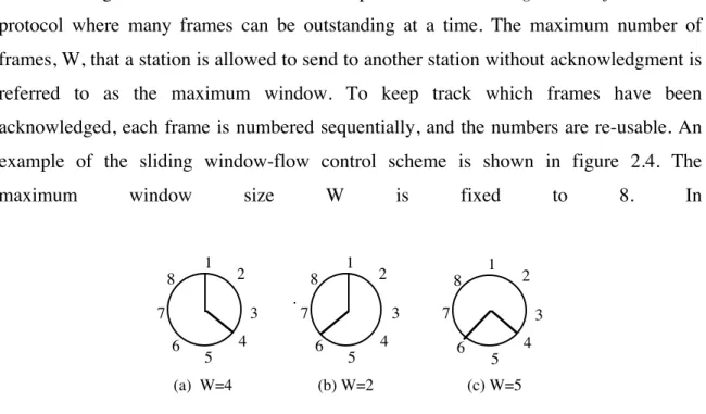
In the stop-and-wait protocol, only one frame is outstanding, i.e. unacknowledged, at a time. A more efficient protocol is the sliding window-flow control
protocol where many frames can be outstanding at a time. The maximum number of frames, W, that a station is allowed to send to another station without acknowledgment is referred to as the maximum window. To keep track which frames have been acknowledged, each frame is numbered sequentially, and the numbers are re-usable. An example of the sliding window-flow control scheme is shown in figure 2.4. The
maximum window size W is fixed to 8. In
1 2 3 4 5 6 7
8 1 2
3 4 5 6 7
8 1 2
3 4 5 6 7 8
(a) W=4 (b) W=2 (c) W=5
Figure 2.4: An example of the sliding window-flow control scheme
The efficiency of this protocol depends upon the maximum window size and the round-trip delay. Let tframe = 1. Then,
a =
tprop
tframe = tprop.
The time to transmit the first frame and receive an acknowledgment is equal to
tframe+2 tprop = 1+2a. If W>1+2a, then the acknowledgment arrives at the sender before
the window has been exhausted, and we have that U = 1. If W<1+2a, then the acknowledgment arrives after the window has been exhausted, and we have
U = W
1+ 2a .
Error detection
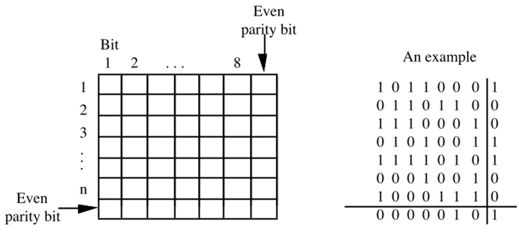
The simplest error detection scheme is the parity check. In this scheme, a parity bit is appended to the end of each frame. A more complex error detection scheme based on the parity check is the longitudinal redundancy check. The data is organized into a matrix, as shown in figure 2.5. There are eight columns, and as many rows as the number of bytes. Each matrix element contains one bit. An even parity check is applied to each row and each
Even parity bit Bit
1 2 . . . 8
Even parity bit
1 0 1 1 0 0 0 1 0 1 1 0 1 1 0 0 1 1 1 0 0 0 1 0 0 1 0 1 0 0 1 1 1 1 1 1 0 1 0 1 0 0 0 1 0 0 1 0 1 0 0 0 1 1 1 0 0 0 0 0 0 1 0 1
An example
1 2 3
n
. . .
column. We observe that the parity bit applied to the last column which contains the parity bits of all the rows, is the same as the one applied to the last row which contains the parity bits of all the columns!
The cyclic redundant check (CRC) is a commonly used error detection scheme, and it is used extensively in ATM networks. The CRC scheme utilizes a pre-determined bit pattern P, which is known to both the sender and the receiver. Let n+1 be the length of this bit pattern. Now, let us assume that we have a k-bit message M to transmitted. The sender shifts M to the left by n bits to obtain the quantity 2n
M, and then divides 2n
M by P. The remainder of that division is an n-bit sequence, known as the frame check sequence
(FCS). The FCS is added to 2n
M and the entire (k+n)-bit message is transmitted to the receiver. The receiver divides the message by the same bit pattern P. The message has been received correctly if the remainder of that division is zero. All single bit errors, and some combinations of erroneous bits can be detected and corrected.
As an example let M=1010001101 and P=110101. Then, the FCS will be 5 bits long and it is calculated as follows. M is first shifted to the left by 5 positions, that is 25
M=101000110100000. Then, 25
M is divided by P resulting to an FCS equal to 01110. Finally, the transmitted message is 101000110101110. If this message is correctly received, when divided by P=110101, it should give a zero remainder.
It is customary to express the bit pattern P in polynomial form. This is done as follows. Each bit is represented by a term xn
, where n is the location of the bit in the pattern, counting from the right-hand-side towards the left-hand side. That is, the rightmost bit corresponds to the term x0
, the second rightmost bit corresponds to the term x1
, and so on. The value of the bit is the coefficient of its corresponding polynomial term. For instance, the pattern 110101 used above is expressed as x5+x4+x2+1.
the entire packet. That is, it is calculated using the header and the payload of the TCP packet. It also used in IP to protect the IP header only. Computing the checksum in TCP is a time-consuming operation, and a considerable speed up can be achieved if it is done in hardware.
Error
0 1 2 3 4 5 2
0 1 2 3 4 5 2
ACK1 ACK2
NAK2 rejected
Sender
Receiver
Figure 2.6: The go-back-n scheme
Error control
Error control refers to the mechanism used to detect and correct errors occurred in the transmission of frames. This mechanism is known as the automatic repeat request (ARQ) and it uses error detection, the window-flow control mechanism, positive and negative acknowledgments, and timers. Errors in the transmission of frames occur because a frame is lost or because it is damaged, that is one or more of its bits have been flipped. Damaged frames are detected by the ARQ mechanism using CRC, and lost frames are detected by observing out-of-sequence frames. Recovery of a lost or damaged frame is done by requesting the sender to re-transmit the frame. Three different versions of the ARQ have been standardized, namely stop-and-wait ARQ, go-back-n ARQ, and selective-reject ARQ. The stop-and-wait ARQ is based on the stop-and-wait window-flow control scheme, whereas the go-back-n ARQ and the selective-reject ARQ are based on the sliding window-flow control scheme.
Error
0 1 2 3 4 5 2
0 1 2 3 4 5 2
ACK1 ACK2
NAK2 Sender
Receiver
Buffered until frame 2 is retrasmitted
Figure 2.7: The selective-reject scheme
B receives a frame correctly, then it sends an ACK with the next frame number that it expects to receive. An ACK may be for several successive frames that have been correctly received. If B receives a damaged frame, say frame i, and it has previously received correctly frame i-1, then B sends a negative acknowledgment (NAK) indicating that frame i is in error. When A receives the NAK, it retransmits frame i plus all other frames after i that it has already transmitted. An example of this scheme is shown in figure 2.6.
Now, let us consider the case where frame i is lost. If B correctly receives later on frame i+1, then it will realize that frame i+1 is out-of-sequence, and it will deduce that frame i is lost. B will then send a NAK indicating that the ith frame has to be re-transmitted. A retransmits frame i plus all other frames after i that it has already transmitted. If frame i is lost and no other frames arrive, then B cannot detect the lost frame. However, for each transmitted frame, A sets a timer. If the timer expires before A receives an ACK or a NAK, A retransmits the frame. In the above case, the lost frame’s timer will expire and A will re-transmit it.
In the selective-reject ARQ scheme only the frame that is in error is retransmitted. All subsequent frames that arrive at B are buffered, until the erroneous frame is received again. This is a more efficient procedure, but it is more complex to implement. The selective-reject scheme is used in TCP. An example of the selective-reject ARQ scheme is shown in figure 2.7.
This protocol is widely used and it is the basis for many other important data link protocols. It was derived from IBM’s data link protocol synchronous data link control
(SDLC). It was later on modified and standardized by ISO as the high data link control
(HDLC) protocol. HDLC was designed to satisfy different types of stations, link configurations, and transfer modes. The following three types of stations were defined:
primary, secondary, and combined. A primary station is responsible for controlling the operation of the link, a secondary station operates under the control of a primary station, and a combined station has the features of both the primary and the secondary station.
Information
Address FCS
Flag
8 bits 8 bits 8 or 16 bits !!! variable 16 or 32 bits 8 bits Flag Control
Figure 2.8: The HDLC frame
Also, the following types of link configurations were defined: unbalanced and balanced. An unbalanced configuration consists of one primary and one or more secondary stations and it supports both full-duplex and half-duplex transmission. A balanced configuration consists of two combined stations and it supports both full-duplex and half-duplex transmission. Based on these station types and configurations, the following three data transfer modes were defined: normal response time mode (NRM), asynchronous balanced mode (ABM), and asynchronous response mode (ARM). NRM is used with an unbalanced configuration. The primary station initiates data transfers to the secondary stations, and a secondary station may only transmit data in response to a command from the primary. NRM is used in multi-drop lines connecting terminals to a host. ABM is used with a balanced configuration, and it is the most widely used transfer mode for a full-duplex point-to-point link. Either combined station may initiate a transmission without receiving the permission from the other combined station. Finally, ARM is based on an unbalanced configuration and it is rarely used.
back-to-back, a single flag may be used to indicate the end of one frame and the beginning of the next one. Obviously, the pattern 01111110 can be easily encountered within a frame, in which case, it will be interpreted as the end of the frame. In order to avoid this from happening, a technique known as bit stuffing is used. The sender always inserts an extra 0 after the occurrence of five consecutive 1’s. The receiver monitors the bit stream looking for five consecutive 1’s. When this pattern appears, the receiver examines the sixth bit. If it is a 0, it is deleted from the bit stream. If it is a 1 and the seventh bit is a 0, the receiver interprets the bit pattern as a delimiting flag. If the sixth bit is a 1 and the seventh bit is also a 1, then it is an error.
1 2 3 4 5 6 7 8
0 N(S) P/F N(R)
1 P/F N(R)
1 M P/F M
0
1
I-frame
S-frame
U-frame S
Figure 2.9: The control field of the HDLC frame
The second field in the HDLC frame is the address field. This is an 8-bit field used in multi-drop lines and it is used to identify the secondary station to which the frame is transmitted. It is not necessary in a point-to-point link.
The third field in the HDLC frame is the control field. It is an 8-bit field, extendible to a 16-bit field, and its structure is shown in figure 2.9. It is used to identify the following three types of frame: information frame (I-frame), supervisory frame (S-frame), and unnumbered frame (U-frame). An I-frame is used to carry data and ARQ control information, an S-frame is used to carry only ARQ control information, and a U-frame is used to provide supplemental link control functions. If the first bit of the control field is 0, then the frame is an I-frame. Otherwise, depending on the value of the second bit, it may be an S-frame or a U-frame. The meaning of the remaining sub-fields is as follows:
N(R): receive sequence
S: supervisory function bits
M: unnumbered function bits
P/F: poll/final bit.
During a typical exchange of information between two stations, say A and B, both stations receive and send data. This means that there are two separate ARQ mechanisms, one for the data sent from A to B and another for the data sent from B to A. The fields N(R) and N(S) in the I-frame are used to carry information for both the ARQ mechanisms piggy-backed on the frames carrying data. N(R) is used by station A to indicate to station B the current status of the ARQ from B to A, and N(S) is used by station A to indicate the sequence number of the frame that it is transmitting to B. S-frames are used when no I-S-frames are exchanged and also to carry supplementary control information.
The information field is only present in the I-frames and in some U-frames. The FCS is calculated using a 16-bit CRC. A 32-bit CRC is optional.
2.5 Synchronous time division multiplexing (TDM)
Time division multiplexing permits a data link to be utilized by many sender/receiver pairs, as shown in figure 2.10. A multiplexer combines the digital signals from N incoming links into a single composite digital signal, which is transmitted to the demultiplexer over a link. The demultiplexer breaks out the composite signal into the N individual digital signals and distributes them to their corresponding output links. In the
multiplexer, there is a small
Figure 2.10: Synchronous time division multiplexing (TDM)
buffer for each input link that holds incoming data. The N buffers are scanned sequentially and each buffer is emptied out fast enough before new data arrives.
The transmission of the multiplexed signal between the multiplexer and the demultiplexer is organized into frames. Each frame contains a fixed number of slots, and each slot is pre-assigned to a specific input link. The duration of a slot is either a bit or a byte. If the buffer of an input link has no data, then its associated slot is transmitted empty. The data rate of the link between the multiplexer and the demultiplexer that carries the multiplexed data streams is at least equal to the sum of the data rates of the incoming links. A slot dedicated to an input link repeats continuously frame after frame, and it is called a channel.
TDM is used in the telephone system. The voice analog signals are digitized at the end office using the pulse code modulation (PCM) technique. That is, the voice signal is sampled 8,000 times per second, or every 125 µsec, and the amplitude of the signal is approximated by a 7- or an 8-bit number. At the destination end office, the original voice signal is reconstructed from these samples. As a consequence of this sampling mechanism, most time intervals within the telephone system are multiples of 125 µsec.
The standard that specifies how to multiplex several voice calls onto a single connection is known as the digital signal level standard or the DS standard. This is a generic digital standard and it is independent of the medium over which it is transmitted.
Digital signal number Voice channels Data Rate (Mbps)
DS-1 24 1.544
DS-1C 48 3.152
DS-2 96 6.312
DS-3 672 44.736
DS-4 4032 274.176
Table 2.1: The North American Hierarchy
Level number Voice channels Data Rate (Mbps)
1 30 2.048
3 480 34.368
4 1920 139.264
5 7680 565.148
Table 2.2: The international (ITU-T) hierarchy
The DS standard specifies a hierarchy of different data rates, as shown in table 2.1. The nomenclature of this hierarchy is DS followed by the level of multiplexing. For instance, DS-1 multiplexes 24 voice channels and it has a data rate of 1.544 Mbps. The higher levels in the hierarchy are integer multiples of the DS-1 data rate. This hierarchy is known as the plesiochronous digital hierarchy (PDH). Plesiochronous means frame synchronous (from the Greek word plesio which means frame).
The DS standard is a North American standard and it is not the same as the international hierarchy standardized by ITU-T. Table 2.2 gives the international hierarchy, which consists of different levels of multiplexing. For instance, level-1 multiplexes 30 voice channels and it has a data rate of 2.048 Mbps. As in the DS standard, the higher levels are integer multiples of the level-1 data rate.
The digital signal is carried over a carrier system, or simply a carrier. A carrier consists of a transmission component, an interface component, and a termination component.. The T carrier system is used in North America to carry the DS signal, and the E carrier system is used to carry the international digital hierarchy. T1 carries the DS-1 signal, T2 the DS-2 signal, T3 the DS-3 signal, and so on. Similarly, EDS-1 carries the level-1 signal, E2 carries the level-2 signal, and so on. Typically, the T and DS nomenclatures are used interchangeably. For instance, one does not distinguish between a T1 line and the DS-1 signal. The same applies for the international hierarchy.
1 2 3 24
1 byte 1 byte 1 byte 1 byte 1 bit . . .
Figure 2.11: The DS-1 format
extra bit is used for signalling. The total transmission rate of the DS-1 format is 24x8+1=193 bits per 125 µsec corresponding to 1.544 Mbps, with each voice channel carrying a 64 Kbps voice.
The DS-1 format can be also used to carry data. In this case, 23 8-bit slots are used for data and the remaining slot is used for control and frame synchronization. Each data slot carries 7 bits of data amounting to a channel of 56 Kbps. The extra bit per slot is used for control.
In the international hierarchy, the level 1 format for voice consists of 32 8-bit slots, resulting to a total transmission rate of 2.048 Mbps. Of these slots, 30 are used for voice and the remaining two are used for synchronization and control.
2.6 The logical link control (LLC) layer
A local area network (LAN) or a metropolitan area network (MAN) consists of a transmission medium which is shared by all the stations that are attached to it. Access to the transmission medium is achieved through a medium access control (MAC) protocol.
The IEEE LAN/MAN Standards Committee, has produced several standards for local and metropolitan area networks, such as the IEEE 802.3 standard for Ethernet, the IEEE 802.4 standard for the token bus, and the IEEE 802.5 standard for the token ring. The logical link control (LLC) protocol was defined in the IEEE 802.2 standard, and it runs over several different MACs.
The other functions of layer 3 are performed by the LLC. This simplifies considerably the OSI stack.
LAN/MAN User
Physical LLC
MAC Transport
User
Physical LLC MAC Transport
Figure 2.12: The OSI stack for LANs/MANs
LLC is concerned with the transmission of link-level PDUs between two stations. Addressing in LLC is achieved by specifying the source and destination LLC users. An LLC user is typically a high-level protocol or a network management function. An LLC user address is referred to as a service access point (SAP). The following services are provided by LLC.
Unacknowledged connectionless service: This is a datagram type of service. It does not involve any flow or error control and the delivery of data is not guaranteed.
Connection-mode service: This is similar to the service offered by X.25. A logical connection is first set-up between two users before any exchange of data takes place. Flow and error control is provided.
Acknowledged connectionless service: This is a service which is a cross between the above two services. Datagrams are acknowledged as in the connectionless mode service, but a logical connection is not set-up.
LLC is modelled after HDLC. It makes use of the asynchronous, balanced mode of operation of HDLC in order to support the connection-mode service. The unacknowledged connectionless service is supported using the unnumbered information PDU, and the acknowledged connectionless service is supported using two new unnumbered PDUs.
indicating the destination and source service access points (SAP). C/R is a 1-bit field indicating whether the frame is a command or response frame. The LLC control field is identical to that of the HDLC with extended sequence numbers. The MAC header contains a MAC control field, the destination address (DA) and the source address (SA), and the MAC trailer carries the FCS value. The address of a station is the physical attachment point on the LAN.
Information
I/G DSAP C/R SSAP LLC
control
LLC PDU
CRC
DA SA
MAC
control LLC PDU
MAC frame
Figure 2.13: LLC and MAC encapsulation
process
X DCE DCE
public packet-switched network
process Y
DTE DTE
X.25 X.25
Figure 2.14: The X.25 interface
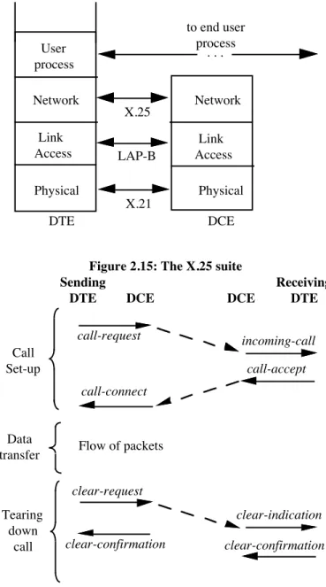
2.7 Network access protocol X.25
architectures while at the same time they are compatible with the end users. The standard specifies the first three layers of the ISO model. As shown in figure 2.15, X.21 is the standard for the physical layer, LAP-B (a subset of HDLC) is the standard for the data link layer, and X.25 is the standard for the network layer. Below, we review some of the basic features of X.25.
DTE DCE Physical Link Access Network User process Physical Network X.21 LAP-B X.25
to end user process
Link Access
. . .
Figure 2.15: The X.25 suite
call-request incoming-call call-accept call-connect Sending DTE DCE Receiving DTE clear-request clear-indication clear-confirmation clear-confirmation Call Set-up Tearing down call Data
transfer Flow of packets
DCE
X.25 provides a virtual circuit service. Two types of virtual circuits are allowed:
switched virtual circuits (SVC) and permanent virtual circuits (PVC). The following events take place in order to set-up an SVC. A pictorial view is shown in figure 2.16.
1. The sending DTE sends a call-request packet to its DCE requesting to establish a virtual circuit to a specific DTE. The packet contains the source and destination addresses and a virtual circuit number selected by the DTE.
2. The network routes the call-request packet to the receiver’s DCE, which sends an
incoming-call packet to the receiving DTE. This packet has the same format as the call-request packet but it utilizes a different virtual circuit number selected by the receiver’s DTE.
3. The receiving DTE, upon receipt of the incoming-call packet, indicates acceptance of the call by sending a call-accept packet to its DTE using the virtual circuit number used in the incoming-call packet.
4. The network routes the packet to the sender’s DCE, which sends a call-connected
packet to the sending DTE. This packet has the same format as the call-accept packet and it has the virtual circuit number used in the original call-request packet.
5. The sending and receiving DTEs exchange data and control packets using their respective virtual circuit numbers.
User data
Q D Group no
Channel no
P(R) M P(S)
1 2 3 4 5 6 7 8
0 1
0
User data
Q D Group no
Channel no
M P(S)
1 2 3 4 5 6 7 8
0 1
0 P(R)
3-bit ARQ sequence numbers 7-bit ARQ sequence numbers
6. The sending (or the receiving) DTE sends a clear-request packet to terminate the virtual circuit. Its DCE sends back a clear-confirmation packet, and forwards the clear-request packet to the destination DCE, which issues a clear-indication packet to its DTE and from which it receives a clear-confirmation packet.
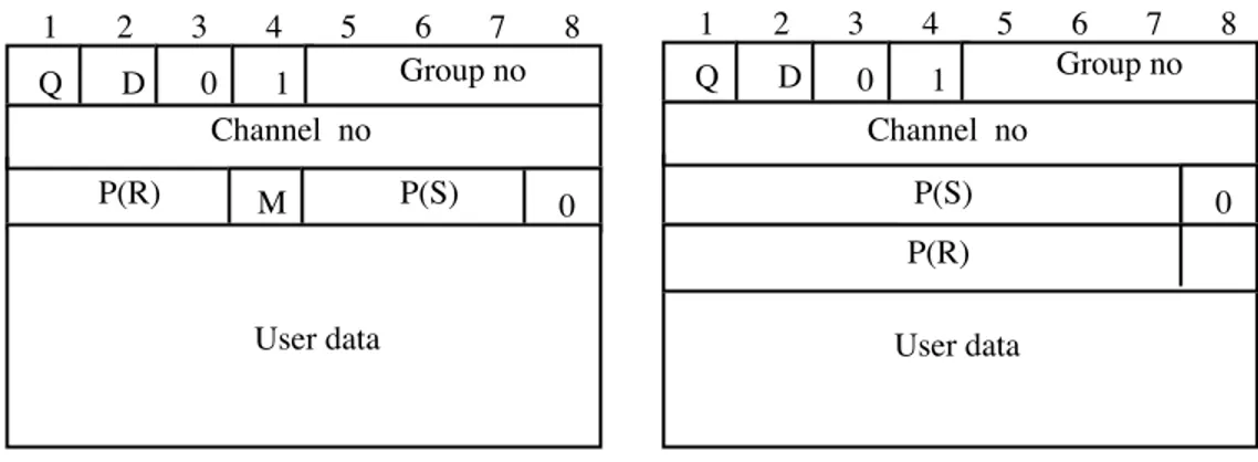
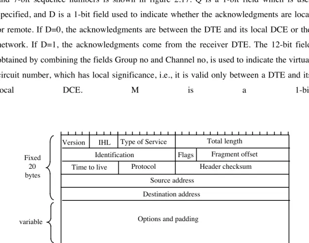
Several types of packets are used in X.25. The format for data packet with 3-bit and 7-bit sequence numbers is shown in figure 2.17. Q is a 1-bit field which is user specified, and D is a 1-bit field used to indicate whether the acknowledgments are local or remote. If D=0, the acknowledgments are between the DTE and its local DCE or the network. If D=1, the acknowledgments come from the receiver DTE. The 12-bit field obtained by combining the fields Group no and Channel no, is used to indicate the virtual circuit number, which has local significance, i.e., it is valid only between a DTE and its
local DCE. M is a 1-bit
Version IHL Type of Service Total length Identification Flags Fragment offset
Time to live Protocol Header checksum
Source address Destination address
Options and padding Fixed
20 bytes
variable
Figure 2.18: The IPv4 header
field used when packet fragmentation is employed. The P(R) and P(S) contain the receive and send ARQ sequence numbers.
2.8 The internet protocol (IP)
model. In this section, we describe the current version of IP, known as IP version 4
(IPv4).
IP provides a connectionless service using packet switching with datagrams. Packets in a connectionless network, such as the IP network, are referred to as
datagrams. An IP host can transmit datagrams to a destination IP host without having to set-up a connection to the destination, as in the case of X.25, frame relay and ATM networks. IP datagrams are routed through the IP network independently from each other, and in theory, they can follow different paths through the IP network. In practice, however, the IP network uses routing tables which remain fixed for a period of time. In view of this, all IP packets from a sender to a receiver typically follow the same path. These routing tables are refreshed periodically, taking into account congested links and hardware failures of routers and links.
IP does not guarantee delivery of IP datagrams. In view of this, if the underlying network drops an IP datagram, IP will not be aware of that. Also, IP does not check the payload of an IP datagram for errors, but it only checks its IP header. IP will drop an IP datagram, if it finds that its header is in error. Lost or erroneous data is recovered by the destination’s TCP using the selective-reject ARQ scheme described in section 2.3.
2.8.1 The IP header
An IP datagram consists of a header and a payload. The IP header is shown in figure 2.18, and it consists of a 20-byte fixed part and an optional part which has a variable length. The following fields are defined in the IP header:
Version: A 4-bit field used to indicate which version of the protocol is used.
Internet Header Length (IHL): This is a 4-bit field and it gives the length of the header in 32-bit words. The minimum header length is five 32-bit words or 20 bytes.
Type of service: This is an 8-bit field that is used to indicate whether the sender prefers the datagram to travel over a route with minimal delay or a route with maximal throughput.