ECE 35
Spring 2017
Homework #4
All homework problems come from the textbook, “Introduction to Electric Circuits”, by Svoboda & Dorf, 9th Edition. Question numbers in the 8th edition is listed for reference.
Question Number Svoboda & Dorf, 8th Edition Svoboda & Dorf, 9th Edition
1 P 5.2-1 P 5.2-1
2 P 5.2-3 P 5.2-3
3 P 5.2-6 P 5.2-6
4 P 5.3-6 P 5.3-6
5 P 5.3-10 P 5.3-9
6 P 5.3-15 P 5.3-13
7 P 5.4-5 P 5.4-5
8 P 5.4-13 P 5.4-12
9 P 5.4-15 P 5.4-14
10 P 5.4-17 P 5.4-16
11 P 5.5-7 P 5.5-7
12 P 5.5-9 P 5.5-8
13 P 5.5-12 P 5.5-11
P 5.2-1 The circuit shown in Figure P 5.2-1a has been divided into two parts. The circuit shown in Figure P 5.2-1b was obtained by simplifying the part to the right of the terminals using source transformations. The part of the circuit to the left of the terminals was not changed.
(a) Determine the values of Rt and vt
in Figure P 5.2-1b.
(b) Determine the values of the current i and the voltage v in Figure P 5.2-1b. The circuit in Figure P 5.2-1b is equivalent to the circuit in Figure P 5.2-1a. Consequently, the current i and the
voltage v in Figure P 5.2-1a have the same values as do the
current i and the voltage v in Figure P 5.2-1b.
(c) Determine the value of the current ia in Figure P 5.2-1a.
Figure P 5.2-1
P 5.2-3 Find vo using source transformations if i = 5/2 A in the circuit shown in Figure P 5.2-3.
Hint: Reduce the circuit to a single mesh that contains the voltage source labeled vo.
Answer: vo = 28 V
Figure P 5.2-3
P 5.2-6 Use source transformations to
find the value of the voltage va in Figure P
5.2-6.
P 5.3-6 Use superposition to find the value of the current i in Figure P 5.3-6.
Answer: i = 3.5 mA
Figure P5.3-6
P 5.3-9 The input to the circuit shown in Figure P 5.3-9 is the voltage source voltage, vs. The
output is the voltage vo. The current source current, ia, is used to adjust the relationship between
the input and output. Design the circuit so that input and output are related by the equation,
vo = 2vs + 9.
Hint: Determine the required values of A and ia.
Figure P 5.3-9
P 5.3-13 Theinput to the circuit shown
in P 5.3-13 is the current i1, the output is
is the voltage vo. The current i2 is used to
adjust the relationship between the input
and output. Determine values of the
current i2 and the resistance, R, that
cause the output to be related to the input
by the equation: vo 0.5i14
P 5.4-5 Find the Thévenin equivalent circuit for the
circuit shown in Figure P 5.4-5.
Answer: voc = –2 V and Rt = –8/3 Ω
Figure P 5.4-4
P 5.4-12 The circuit shown in Figure P 5.4-12 contains an adjustable resistor. The resistance R
can be set to any value in the range 0 ≤ R ≤ 100 kΩ.
(a) Determine the maximum value of the current ia that can be obtained by adjusting R.
Determine the corresponding value of R.
(b) Determine the maximum value of the voltage va that can be obtained by adjusting R.
Determine the corresponding value of R.
(c) Determine the maximum value of the power supplied to the adjustable resistor that can be
obtained by adjusting R. Determine the corresponding value of R.
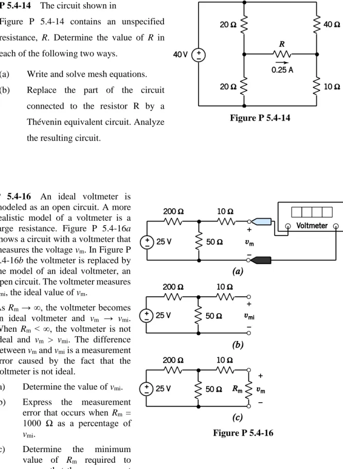
P 5.4-14 The circuit shown in
Figure P 5.4-14 contains an unspecified
resistance, R. Determine the value of R in
each of the following two ways.
(a) Write and solve mesh equations.
(b) Replace the part of the circuit
connected to the resistor R by a
Thévenin equivalent circuit. Analyze
the resulting circuit.
Figure P 5.4-14
P 5.4-16 An ideal voltmeter is modeled as an open circuit. A more realistic model of a voltmeter is a large resistance. Figure P 5.4-16a
shows a circuit with a voltmeter that measures the voltage vm. In Figure P 5.4-16b the voltmeter is replaced by the model of an ideal voltmeter, an open circuit. The voltmeter measures
vmi, the ideal value of vm.
As Rm → ∞, the voltmeter becomes an ideal voltmeter and vm → vmi. When Rm < ∞, the voltmeter is not ideal and vm > vmi. The difference between vm and vmi is a measurement error caused by the fact that the voltmeter is not ideal.
(a) Determine the value of vmi.
(b) Express the measurement error that occurs when Rm = 1000 Ω as a percentage of
vmi.
(c) Determine the minimum value of Rm required to ensure that the measurement error is smaller than 2 percent of vmi.
P 5.5-7 Determine the value of the resistance R in the circuit shown in Figure P 5.5-7 by each of the following methods:
(a) Replace the part of the circuit to the left of terminals a–b by its the Norton equivalent circuit. Use current division to determine the value of R.
(b) Analyze the circuit shown Figure P 5.5-6 using mesh equations. Solve the mesh equations to determine the value of R.
Figure P 5.5-7
P5.5-8 Find the Norton equivalent circuit ofthis circuit:
P 5.5-11 Determine values of Rt and
isc that cause the circuit shown in
Figure P 5.5-11b to be the Norton
equivalent circuit of the circuit in
Figure P 5.5-11a.
Answer: Rt = 3 Ω and isc = –2 A
P 5.6-1 The circuit shown in Figure P 5.6-1 consists of two parts separated by a pair of terminals. Consider the part of the circuit to the left of the terminals. The open circuit voltage is voc = 8V, and the short circuit current is isc = 2A.
Determine the values of
(a) The voltage source voltage, vs, and the resistance R2.
(b) The resistance R that maximizes the power delivered to the resistor to the right of the terminals, and the corresponding maximum power