Final Design Report
Team Mountain Arm
Conner Magnuson - [email protected]
Marco Lopez - [email protected]
Jordan Ambrose - [email protected]
Table of Contents
Executive Summary Page 3
Chapter 1: Introduction Pages 3-7 Chapter 2: Background Pages 7-13 Chapter 3: Design Development Pages 13-20 Chapter 4: Description of the Final Design Pages 21-26 Chapter 5: Product Realization Pages 26-32 Chapter 6: Design Verification Pages 32-38 Chapter 7: Conclusions and Recommendations Pages 38-39
Acknowledgements Page 39
Executive Summary:
QL+ Challenger, US Navy Veteran, and transhumeral amputee Cassie Perando needed a way to backpack comfortably and independently while wearing a transhumeral prosthesis, as this is something that she enjoys doing often. The current prosthesis she wears causes pinching while wearing a backpack. To eliminate this issue, we decided to design and create a dynamic, pin-lock socket. This design decision allowed for a comfortable fit for Cassie that will not interfere with the backpack straps. As a secondary suspension system, we designed a sports bra with straps that attach to her opposing side and connect to the front and the back of the prosthesis’ socket in order to spread the force of the prosthesis over a larger surface area. To complete the prosthesis, the following components were purchased: E400 elbow, a NEXO Forearm Kit, a Quick Disconnect wrist adapter, and a stainless steel cable system. After testing individual components and obtaining feedback from Cassie, the components were assembled into a final product. The product had to be built separately due to COVID-19. The handoff of the product to Cassie was postponed due to a final fitting that needs to occur in person. This could not be performed during the end of spring quarter due to the pandemic, but is expected to occur in mid-June. Overall, with the
successful manufacturing of the final product, regardless of challenges stemming from the pandemic, we were able to meet our engineering and customer requirements, while keeping the cost low.
Chapter 1
Introduction:
The proposed project, a backpacking-compatible transhumeral prosthesis, was led by the Cal Poly senior design team “Mountain Arm,” and sponsored by Quality of Life Plus (QL+). QL+ is a nonprofit
organization that facilitates the innovation of new devices to help aid America’s patriots, ranging from those who have served in the military to first responders. QL+ finds these patriots in need or
“challengers” as QL+ calls them, and then partners with different universities such as Cal Poly in order to have student projects to create adaptations or devices to meet the challenger’s needs. QL+ has found the challenger Cassie Perando, a US Navy Veteran, and has sponsored team Mountain Arm to head the project Cassie has created.
Cassie is a left-transhumeral amputee (above the elbow amputation) who uses a body-powered prosthesis. This means Cassie uses shoulder movements and arm flexions to lock her prosthesis’s elbow and to open and close the metal hook, or terminal device, attached at the end of her prosthesis. Living in Oregon, Cassie enjoys going backpacking outside. A problem for Cassie when she backpacks, is that her backpack strap rubs and gets pinched at her shoulder where the backpack meets the attachment of her prosthesis. Since her prosthesis is body powered, it is important that the strap does not get in the way of her
movements. Our goal was to build a new prosthesis that changes how she attaches it to her arm so that it does not get in the way of her backpack.
able to design a modified terminal attachment for Cassie’s new backpacking prosthetic that allows her to perform fine motor skills such as these. However after consulting with the QL+ provided prosthetist Tim Bump and local prosthetist Matt Robinson, the scope of our project would have been too large if our team focused on both the arm attachment to the residual limb and designing a terminal device.
Based on the fact that we only had nine months to design, build, and test our device, we came to the conclusion to focus on designing the socket and attachment of the prosthesis to Cassie’s residual limb as this solves the main problem of Cassie’s ability to backpack while wearing a prosthesis. We additionally built the rest of the arm portion of the prosthesis using a purchased kit that is available through the company Fillauer.
This project not only could have an impact on Cassie’s lifestyle, as this device is meant to help her when she is out backpacking, but has the potential to affect other amputees' lives as well. The design of this device could be transferable to other amputees who also enjoy similar activities in the outdoors as Cassie does.
Team Mountain Arm is made up of four Cal Poly engineers who have partnered with QL+ and Cassie for their senior design project class. This project took place over the span of one school year at Cal Poly, or 9 months.
The first quarter of the school year, the team learned more about Cassie’s needs and problems, began background researching devices that already exist, learned to work as a team, brainstormed design ideas, and decided on a conceptual design. Winter quarter was spent finalizing this conceptual design and beginning the process of building our prototype. Spring quarter was spent building the prototype, testing and reiterating the design, and finalizing the prosthesis to meet Cassie’s needs of being compatible with her backpack.
Objectives:
Our primary objective was to design a prosthetic arm that would improve the quality of life for our client, Cassie Perando, by enabling her to engage in her pastime of backpacking comfortably and independently. More specifically we intended to improve comfort around the shoulder, be compatible with multiple backpacks, lightweight, customized to her, and stay within the allocated budget.
Table 1: Engineering Requirements
Mountain Arm Formal Engineering Requirements
Spec. # Parameter Description Requirement of
Target (units)
Tolerance Risk Compliance
1 Price 5,000 USD Max L S
2 Shoulder Lateral Range of Motion
3 Range of motion of elbow
120 Degrees Min L S, I
4 Distance from Backpack Strap to Prosthesis
0.25 inches Min L I, T
5 Forearm Length (Olecranon to Styloid)
9.25 inches ±0.25 L I, T, S
6 Forearm Circumference 9.5 inches Max L I, T, S
7 Wrist Circumference 6 inches Max L I, T, S
8 GIH Joint (shoulder) to Elbow
13.5 inches ± 0.5 inches L I, T, S
9 Force to Accidently Remove Device
25 lbs Min M I, T,S
10 Corrosion Rate 0.02 mm/year Max M A, S
11 Temperature Operating Range
20 to 120 °F Min, Max M A, T, I
12 Weight (without terminal device)
5 lbs Max M A,S,I
● Risk: high (H), medium (M), or low (L),
● Compliance: analysis (A), test (T), similarity to existing designs (S), and inspection (I)
The range of motion requirements are based on minimum values for an adult female [1]. We believe that the range of motion of the elbow is at low risk to meet compliance, whereas the shoulder is at a slightly higher due to inherent risks involved with this movement and restriction of motion through use of straps. The range of motion measurements may be tested with low precision by using a protractor.
The anthropometric requirements for forearm length, forearm circumference, wrist circumference, and shoulder to elbow length requirements are all based on measurements of Cassie’s right arm and residual left limb. These requirements are included in order to balance the symmetry between her right arm and the prosthesis. The circumference requirements are set as max in order to ensure that clothing that fits over her right arm will also fit with her prosthesis. These requirements were low risk due to our ability to design around Cassie’s dimensions and make modifications where necessary if dimensions are out of spec when we have the final meeting with Cassie.
prosthesis while the user wears it. If the prosthesis slides off while being worn, then it fails the test. There is a possibility when we perform the final fitting with Cassie,we will be able to perform this test.
Since the prosthesis will be used in a wet environment, sweat from exercise and/or potential rain/humidity while backpacking, it is important to put requirements on the corrosion rate of the materials used in manufacturing the prosthesis. In order to verify this requirement, we chose materials based on tabulated data on corrosion rates.
The temperature operating range requirement is specified in order to give an upper and lower limit on the temperature of the working environment. Plastics and metals behave differently depending on the
temperature they are working in. When plastics get cold, they become stiffer and easier to break. Furthermore, when metals vary in temperature, they change in size due to thermal expansion. Critical components such as hinges, rubber rings, and silicone sleeves can change depending on the temperature, so we want the device to work within the range of temperatures one would likely encounter while
backpacking. To test this requirement, we had hoped to have put the finished device in an environmental chamber and check the performance of the hinges and plastic components at either extreme. However, due to COVID-19 this test could not be performed and have to instead rely on the research that we put into choosing materials that will work for the temperature range needed.
The weight of the prosthesis, minus the weight of the terminal device, has been set to a maximum value of 5 pounds. During our third meeting with Cassie, she informed us that her right arm weighs 7 lbs and her current carbon fiber prosthesis weighs about 5 lbs (with the terminal device). Cassie informed us that the lighter the prosthesis is the better, and since carbon fiber is not being used in this design, keeping the prosthesis under 5 pounds was a medium risk requirement. In order to test this requirement, we analyzed the weight of the prosthesis by designing in 3D CAD software, inputting material densities, and summing up total weight. Furthermore, once the final prosthesis was manufactured, we were able to weigh the prosthesis.
Management Plan:
For this project, Amanda is the main contact point for both Cassie and Vanessa. As a whole, the work has been evenly distributed between group members. Fall quarter we all worked together on everything in order to be cohesive in our design decisions. In order to efficiently use the time allotted to us for this project, the work on the secondary attachment and socket design was split at the beginning of winter quarter. Amanda and Jordan’s primary task was to work on the secondary attachment while Conner and Marco were tasked to finish working on the socket design. This does not mean all work was separated, the team still worked together on major decisions and provided support for the other duo’s task.
our sponsor for updates. With Cassie having limited cell service, contacting her was always a challenge. We tried to speak with Cassie biweekly Fall quarter when design decisions were being made, but it was dependent on her availability. Winter quarter we met only a couple of times with Cassie and in spring quarter we mainly communicated with Cassie through our QL+ representative, Vanessa Salas. It was less necessary to gain feedback from Cassie spring quarter as we had determined the customer requirements and therefore focused on building the prosthesis.
Due to COVID-19, our timeline for spring quarter got shifted, and relatively simple tasks became more difficult . With everyone separated across the state, Conner became in charge of manufacturing the prosthesis at home while Amanda sewed the secondary attachment in SLO. We all continued to meet weekly over Zoom to work on the project and discuss decisions that needed to be made.
Chapter 2
Background:
After looking at different existing products that also attempt to create compatibility between backpacks and upper-limb prosthetic devices, it was evident that there have been a variety of designs. The primary method for securing a body-powered, above-elbow prosthetic device is by different strap/harness techniques, according to Lt. Robert J. Pursley’s “Harness Patterns for Upper-Extremity Prostheses” article. The first harness type is the Figure 8 Harness exemplified in Figure 1, which our challenger Cassie Perando currently utilizes.
Figure 1: Figure 8 Harness for Upper-Limb Prosthesis [1]
consisting of a lateral support strap that rests above the cross on the user’s back. The second above-elbow harness type found is the Chest-Strap Harness, shown in Figure 2.
Figure 2: Chest Strap for Upper-Limb Prosthesis [1]
This type of harness is recommended for lifting heavy loads, which could be seen as an advantage when backpacking. However, chest straps tend to be less secure, causing movement that results in rubbing and discomfort. The last type of harness researched is the Above-Elbow Triple Control Harness, shown in Figure 3.
Figure 3: Above-Elbow Triple Control Harness for Upper-Limb Prosthesis [1.1]
control and operate the terminal device without having to first lock the elbow, and a disadvantage of this type of harness is the complexity and difficulty of the fabrication of this device [1.1].
After speaking with Cassie, she suggested trying to create a prosthesis design that includes a pin lock system, to replace the need for a harness. However, prosthetist Matt Robinson recommended against getting rid of the harness or any other secondary system of attachment entirely. Instead, we decided to use a secondary system of attachment that utilizes a sports bra that attaches to the prosthesis. Cassie specified that she does not need an active arm, she only needs it to be passive, so this eliminates the need for a cable that actuates her terminal device. After speaking to Cassie winter quarter however, we realized some problems might occur if we choose to get rid of it, and so we decided to add the cable. The other cable on her prosthesis locks and unlocks her elbow which she already pulls on manually, so we changed that cable to a pull tab. The usage of the pin lock system is much more common for lower-limb
prostheses than upper-limb prostheses. An example of a pin lock system is shown below in Figure 4.
Figure 4: Pin Lock System General Example [2]
The pin lock system works by consisting of a drawdown clutch-lock and cushioned end-pad. The pin lock interfaces with a locking liner, which is placed into the distal end of the socket, to ultimately create a connection between the rest of the prosthetic arm and the user’s residual limb. It can then be tightened down with the shuttle-lock and will remain securely engaged, until the user presses the shuttle-lock to release the attachment [2.1].
A product that seemed applicable to the specific Backpacking Prosthetic project is Ottobock’s Body Harness for trans-humeral amputees. This prosthetic device uses a body harness that looks very similar to backpack straps, shown in Figure 5.
Figure 5: Ottobock’s Body Harness for Upper-Limb Prosthesis [3]
According to their website, it is the “world’s first soft harness for above-elbow
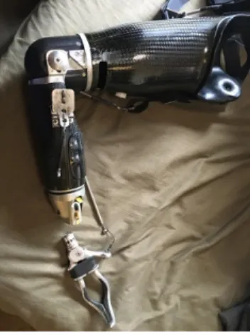
fittings with myoelectric or passive elbows, features an arm sling and sleeve that are completely removable” [3]. It allows for a more natural body-powered movement and higher individual control. This could relate to a possible solution to Cassie’s proposed project because the straps of this prosthetic harness relate so closely to those of a backpack.In obtaining background information, it was also helpful to get more information from Cassie about her current prosthesis and terminal device, both of which are shown below in Figure 6. Between her
Figure 6: Cassie’s Current Transhumeral Prosthesis
After changing the scope of the project to focus primarily on the attachment system and talking to QL+’s recommended prosthetist Tim Bump, we found Fillauer’s NEXO line that would allow us to purchase a kit to eventually build the prosthesis, rather than trying to redesign and recreate everything ourselves. All of the NEXO systems are very simple to build and are 50% lighter than existing prostheses. The NEXO Transhumeral system, seen in Figure 7, allows for an easy connection to a variety of different elbows and includes a damping ring to reduce vibration [4].
Figure 7: Fillauer’s NEXO Transhumeral System [4]
There are a total of four main NEXO Transhumeral Kits. The NEXO Kit for Medium Elbows has two options-- the Kit with the Quick Disconnect Wrist and the Kit with the Friction Wrist. The NEXO Kit for Large Elbows has the same two kit options with the Quick Disconnect Wrist and the one with the Friction Wrist. There are also elbows available for purchase, such as the E-200 Medium Elbows (2.4 inch
diameter) for NEXO with 11 and 9 locking positions, the E-400 Large Elbows (2.8 inch diameter) for NEXO with 11 and 8 locking positions, and the E2 Electric Elbow with a 2.4 inch diameter or a 2.8 inch diameter [4].
prosthetic arm in this case. It is a very significant part of the decision matrix because the socket-residual limb interface, especially the pressure and force distribution, can have a tremendous effect on patient satisfaction and function. A dynamic socket, shown in Figure 8, is adjustable to volume changes and consists of an elastomeric liner that is embedded with a multitude of sensing elements that continuously monitor the socket fit and fluidic bladders/channels that allow for an incompressible fluid to move into or out of the bladders to achieve the desired fit [5]. In comparison, a static socket is more rigid and
non-adjustable, making it potentially less comfortable for the user, especially during activities such as exercise in which volume changes in the limbs are inevitable.
Figure 8: Example of a Dynamic Socket with Elastomeric Liner [5]
In addition to researching a variety of designs, there are also many standards and codes that need to be reviewed and considered for this project. Of the World Health Organization’s Standards for Prosthetics and Orthotics, [6] the applicable standards for this project that we will address include but are not limited to:
No. 15: Strategies for raising awareness about prosthetics and orthotics services should be established, including rights-based, social and economic arguments.
No.18: International standards should be used for national classification of prosthetic and orthotic products.
No. 24: Affordable prosthetic and orthotic products that are cost–effective, of good quality and context appropriate should be developed and made widely available.
No. 39: Service users should be given the opportunity to choose their service provider and technology, including components and materials, according to their need, among the options available in the country and the limits set for financing or reimbursement.
No. 43: Maintenance and repair services should be an integral part of a prosthetics and orthotics service delivery system.
No. 48: Prosthetics and orthotics service providers should define and adhere to a plan for equipment maintenance and replacement.
No. 56: Users or caregivers should make the final decision about the acceptability of the fit and function of the prosthesis or orthosis
No. 58: Prosthetics and orthotics service users should be followed up regularly.
Chapter 3
Design Development:
Following the Project Requirements Document due in early fall, Team Mountain Arm continued to meet with Cassie to finalize the specifications that she wanted for her prosthesis. Cassie expressed that she was content with using her right arm to manually adjust the elbow, wrist, and terminal device of the
prosthesis. Manual adjustment eliminated the need to introduce a cable system to our prosthesis, however as stated above, later conversations led us to realize a cable system was still needed. Team Mountain Arm conducted further research on the following three areas: possible ways a transhumeral prosthesis can be attached to the body, possible materials available that would best suite the specifications (ex. a
.
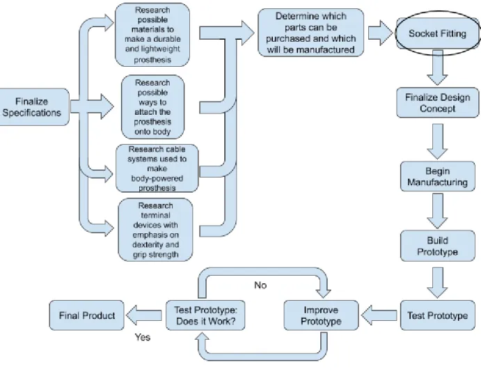
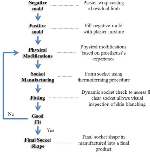
Figure 10: Socket Fitting Flowchart
The fitting process of the socket is part of the project (circled in Figure 9) that is started before the finalization of the design concept. Traditionally, sockets are made by a series of positive and negative molds which are used to form the socket shape. We began this process by 3D scanning Cassie’s residual limb and made a positive mold of her current pin lock socket that she uses for swimming. This positive mold was then wrapped with plaster to form a negative mold. Later, this negative mold was filled with a plaster mixture to form a positive mold representing the shape of the residual limb plus the silicone liner. The positive mold will then be altered by adding or removing plaster in order to decrease or increase the pressure distribution in certain areas. Once an acceptable shape was achieved and deemed by the prosthetist’s experience, a clear thermoplastic socket was manufactured.
Figure 11: Top Attachment Concepts
We limited the possible ways to attach a prosthesis into 6 top concepts. The top concepts chosen were: a pin lock system (Figure 11A), a lanyard system (Figure 11B), a squeeze ratchet system (Figure 11C), a horizontal pin lock system (Figure 11D), a removable harness attachment system (Figure 11E), and a socketless socket system (Figure 11F). For the pin lock system (Figure 11A) description, refer to Figure 4 in the background section. The lanyard system(Figure 11B) is similar to the pin lock system, except instead of using a pin to lock the prosthesis into place, it uses a strap. The squeeze ratcheting system (Figure 11C) uses knobs located at the bottom of the socket to adjust the size until a proper fit onto the residual limb. The horizontal pin lock system (Figure 11D) is also similar to the regular pin lock system, but instead of having a pin (attached to a liner) latching onto the locking mechanism (bottom of the socket), the pin and locking mechanism is switched. The locking mechanism is attached to the liner where it can be inserted at the bottom of the socket which would then allow for a pin to be inserted on the side of the socket and through the locking mechanism. The removable harness system (Figure 11E) is just a harness with an easily removable attachment point to the socket of the prosthesis. The socketless socket system (Figure 11F) is a highly adjustable and breathable socket that uses many straps to tighten or loosen the socket onto the residual limb.
make our own liner with the locking mechanism attached to it. However, Matt Robinson highly suggested against developing our own liner, which thereby eliminated this concept. The removable harness
attachment system was also not chosen because that would end up leaving the prosthesis as a hanging weight, which is not recommended. Both the squeeze ratcheting system and the socketless socket were examples of dynamic sockets. We really liked the idea of the dynamic socket, so we decided to
incorporate an adjustable socket into our design which will be described in more detail below.
Chosen Attachment System
After going through the decision process as explained prior, we decided that the best attachment system to Cassie’s residual limb would be the pin lock system. This system would solve the problem of getting in the way of the backpack strap because the prosthesis won’t go up and over her shoulder the way her current prosthesis does. Instead, the prosthesis won’t ride quite as high up her arm and shoulder, thus the backpack strap won’t get caught.
Although other design attachment systems we came up with would also solve this problem, what aided in our decision to go with the pin lock, was the fact that Cassie already uses a pin lock system. She uses this system for another one of her specialized prostheses (for swimming), and she prefers this attachment system over her current attachment system because the pin lock is more comfortable to wear. This made the pin lock the ideal choice because not only does it solve the problem of backpacking, but our user already knows how to use this system and is comfortable using it.
Figure 12 : Cassie using her Swimming Pin-Lock Prosthesis
wears her pin lock system while she runs because it’s more breathable than her regular day-to-day prosthesis.
Figure 13 : Friction Forces Between Skin and Silicone Liner [9]
Secondary Suspension
In addition to the primary attachment, we decided to incorporate a secondary suspension system to be attached to the prosthesis. After talking with local prosthetist Matt Robinson, he said we need a secondary suspension system in order to ensure Cassie’s prosthesis isn’t just a “hanging weight” when she is
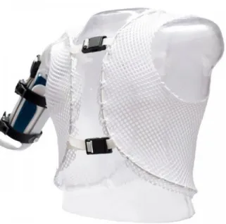
backpacking.This will help to redistribute the force from the prosthesis to more of her body instead of just her shoulder and residual limb. We debated designing either a sports bra or breathable vest that Cassie will wear for this attachment.
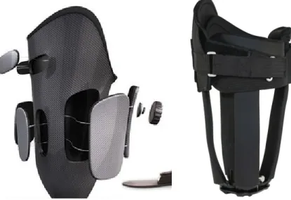
Figure 14 : Example of Secondary Suspension Vest
Socket Type
Our team made the decision to move forward with a dynamic socket. As explained prior, dynamic sockets are adjustable which makes it the ideal choice for our design for several reasons. Since Cassie lives in Oregon and we are located in California, it makes it difficult for us to meet with her often enough to make sure the socket has a perfect fit. With the dynamic socket this will ensure Cassie has a fit that she likes and will be happy wearing because she can adjust it to her preference.
We worked winter quarter to finalize the design for our socket. We researched different thermoplastics and other materials to make the socket out of. We additionally researched which adjustment system we wanted to use.
Socket Design - design decision: Adjustable Panels vs QuickFit Straps
Figure 15: Adjustable Panels vs. Adjustable Straps
For the type of adjustable strap, we decided to go with the Click Medical QuickFit strap. We chose this option because it's designed to be operated by one hand, designed for small 1mm adjustments, and are able to withstand loads of 150+ lbs (see attachment E). These straps are often used in orthopedics for making quick adjustments as seen in the right side of Figure 16. QuickFit straps come in three different widths: 1, 1.5, and 2 inches. After consulting with prosthetist Tim Bump, we decided to go with two 1 inch straps.
Chapter 4
Description of the Final Design
Entire Device
Figure 17: Overall layout Model and actual finished product.
Arm Design
Figure18: Labeled layout of prosthesis.
Figure 19. Customized chicago screw for attaching socket to elbow assembly
The E-400 and NEXO transhumeral forearm kit was purchased from Fillauer. The NEXO transhumeral kit consists of a left and right saddle upright, an upright connector, dampening ring, 5 PEEK rods, and a Quick Disconnect wrist. Details on both the E-400 elbow and NEXO kit are in Appendix E.
Figure 20: A, strap across the back. B, right side of sports bra velcroed with strap. C, velcro for ideal strap tightness. D, front with velcro securely fastened down.
Secondary Attachment Design
the sports bra. The strap will continue to be wrapped and velcroed around the sports bra to the front center point of the sports bra. The strap is then twisted and pulled up and diagonal to the left side of her body. A buckle will be permanently attached to the front portion of her prosthesis. The strap will be through the buckle permanently. The strap can then be pulled back down on itself to the ideal tightness and velcroed back to the strap. We are additionally incorporating a stainless steel cable system so Cassie can actuate her terminal device and easily change elbow positions. The cable system is currently not built into our final prototype because the cable needs to be attached in person as mentioned earlier. Cassie is planning to make a trip mid-June so the cable system will be incorporated at that time. A list of all components and sizes can be referred to in Appendix F.
Cost breakdown
QL+ did not give us a maximum budget, but we planned from the beginning of the project to keep the costs below what is currently available on the market for a similar device. In our research, we’ve seen that a body powered prosthesis will range anywhere between 5,000 to 10,000 US dollars with insurance agencies fronting the cost. Since we did much of the work ourselves, this was placed at low risk and compliance will be based on similarly existing designs. Our preliminary cost estimate came to $2000 (can be seen in Appendix D), which is well below the requirement of $5,000.
Additionally, we received an educational discount from Fillauer for the E-400 elbow and the NEXO kit, which happened to account for a bulk of the cost. We received the E-400 elbow for free, leaving us to only need to purchase the NEXO Kit and the Quick Disconnect Wrist. This then left our total cost at $1339.60. A breakdown of the final cost for our project can be seen in Appendix J.
Overall, keeping our costs low enables the QL+ organization to fund more projects to help more military vets. Since we made only one prosthetic arm as this is completely customized to Cassie, there was no need to worry about mass manufacturing costs. Additionally, prostheses in general cannot be mass manufactured as each prosthesis has to be tailored to the wearer’s exact fit.
Material, Geometry, Component Selection
Socket
As stated before in the background, we built a dynamic socket with a pin lock and liner. Additionally, we chose to use QuickFit straps for making adjustments. With this in mind, we needed to be able to select a material that would be best suited for the socket.
Thermoplastic sheet materials are typically more widely used in the field of orthopedics technology. Additionally, ratchet tightening mechanisms like the Click Medical QuickFit straps as seen in Figure 17 are often used on orthopedics. The group of polyethylene (PE) and polypropylenes (PP) are particularly well suited for the fabrication of prostheses and orthoses [16]. These materials are lightweight and offer long-term functionality in orthopedics technology as well as prosthetics.
because of its narrow temperature forming range and sensitive surface in a thermoplastic state. To achieve good results, high performance heating devices such as infrared ovens and precision application
techniques are required [15].
We then needed to decide between the two main types of polypropylenes: polypropylene copolymer (PP-C) and propylene homopolymer (PP-H). PP-H has a high strength-to-weight ratio and is stiffer and stronger than the copolymer [13][14]. These properties combined with good chemical resistance and weldability make it a material of choice in many corrosion resistant structures. PP-C is a bit softer but has better impact strength. It’s tougher and more durable than propylene homopolymer[13][14]. We
ultimately decided to go with Thermolyn PP-C because it tends to have better stress crack resistance and greater toughness at lower temperatures than homopolymer at the expense of a small reduction in other properties [15].
Secondary Attachment (Sports Bra)
For the sports bra, we chose a large Nike Sports Bra (seen in Figure 17). This specific sports bra was chosen from the market because this is an item that Cassie currently wears often and is very comfortable with. The strap will be a Nylon Climbing Webbing Strap with Nylon Thread. This strap is made for rock climbing and is extremely durable yet smooth against the skin. The nylon component of the strap allows it to be elastic enough to accomodate for the prosthesis, but it will not overstretch to the point where it is not able to appropriately support the prosthesis from her opposing side. The strap is also outdoor compatible. The strap will be attached to the sports bra through the use of velcro. Velcro is easily incorporated into the sports bra fabric and was recommended to us by Matt Robinson, the local prosthetist. Additionally a small piece of vegetable leather will be sewn on the end of the strap that is riveted to the socket in order to prevent fraying of the strap. The strap will be attached to the prosthesis using an 18-8 Stainless Steel Anchor Plate 1 ¾” Webbing Width. This component and material were chosen because it is lightweight and durable. The webbing width being 1 ¾” allows it to be able to effectively work with the 1 inch climbing strap while also allowing for an adequate amount of clearance to ensure the two components work together properly. A Stainless Steel cable system will additionally be incorporated once we have a final fitting with Cassie.
Safety Considerations
one-inch Quick Fit straps addition to aid in the socket’s fit. The straps are adjustable to tighten and loosen as necessary to ensure a perfect fit. Tightening the straps too much could lead to discomfort for Cassie’s residual limb. In addition to this, straps could also have the potential to snap, causing potential
discomfort. A safety consideration regarding the sports bra component is potential discomfort due to the sports bra being too tight and rubbing. We will ensure to thoroughly explain all of these safety
considerations with Cassie so she is aware of the potential hazards while utilizing and wearing the prosthesis and additional components (Appendix H).
Maintenance and Repair Considerations
It is recommended that Cassie cleans the inside of the socket with either soap and water or alcohol
cleaning swabs each day in order to prevent the socket from smelling and reduce bacteria from growing in the socket. If using an alcohol swab, it is recommended to let the socket fully dry before putting on to reduce drying out the skin on her residual limb.
In terms of maintenance, it is recommended Cassie stops by a prosthetist every 6 months for routine maintenance checks. There, a professional can make any minor adjustments as needed. This is standard procedure for any prosthesis. Additionally, if Cassie hears any squeaking or cracking, she should
immediately go see the prosthetist. Majority of the socket parts will be under warranty and the prosthetist can quickly find a replacement part if that is the need. The quickfit straps could break from cinching too tight. We are purchasing extras for testing purposes and will give these to Cassie to use as a replacement if one of her prior straps break.
In terms of the sports bra, five modified sports bras were made for Cassie so in case she loses them or they wear out, she has plenty. It is recommended she wash the modified sports bras just like she’d wash a regular one as washer machine friendly velcro was used. Furthermore, an extra QuickFit strap will be included with the prosthesis in the event that one of the straps on the prosthesis fails.
Chapter 5
Product Realization
Manufacturing Process: Dynamic Socket
Figure 21: Polyurethane foam on surrounding static socket.
Initially, we intended to process the thermoplastics at the Hanger Clinic in San Luis Obispo under the guidance of Matt Robinson using the following process [15]:
1. Place wet plaster cast in the oven.
2. Set the oven to recommended processing temperature for the thermoplastic sheet material. 3. After approx. 1 hour (infrared oven) – 11⁄2 hours (convection oven) place the thermoplastic sheet
material in the oven next to the wet plaster cast. 4. Allow the sheet to sag by at least 1/3 of the model.
5. Take out the plaster model, immediately clamp it into the vacuum suction device and prepare it for vacuum forming. (silicone grease to the dummy/plaster model)
6. Vacuum-form the sheet as usual.
7. Turn off the vacuum after cooling to room temperature and then demould it.
However, due to COVID-19, we were unable to thermoform the sockets ourselves. Instead, we
outsourced the manufacturing of the inner and outer sockets to a shop based out of Santa Barbara. Once the sockets arrived, Conner signed a release of liability agreement and brought the parts home for the final manufacturing and assembly.
Figure 22: Images of coping saw, spiral scroll saw blade, and dynamic socket with cutouts .
In order to do a carbon fiber layup from home, some ingenuity was required due to lack of resources. After doing some research, a vacuum bagging process was found that uses a FoodSaver® food vacuum bagger [3.1]. The carbon fiber layup for the static socket was done using three layers of a carbon fiber/fiberglass weave, two longitudinally and one laterally, with general purpose epoxy resin applied with a brush to each layer. Once all the layers were positioned, a small balloon was inflated and placed in the opening of the socket to hold the fibers in place. Next, a layer of teflon release fabric, perforated film, and breather cloth were placed around the socket. This was then placed in a double-sealed bag and vacuum was drawn till excess resin was seen in the breather cloth. Next, the bag was sealed and resin cured for 12 hours at room temperature.
Figure 23 A, B, and C: Carbon fiber layup process.
Figure 24: Finished carbon fiber static socket.
Once the static socket was secured to the elbow, shrink-wrap tubing was added to the pull-tab to enable easy one-handed locking and unlocking operation of the elbow. Next, a cable clamp was screwed into the socket to hold the cable in place. Lastly, a ¼ inch hole was drilled through the socket to insert the release button for the Shuttle Lock.
Figure 25: Assembling Nexo Transhumeral kit.
in-lb. Then, the Damping ring was slid over the PEEK rods. Lastly, the quick disconnect wrist was attached with set screws tightened to 20 in-lb.
Manufacturing Process: Secondary Attachment
Velcro was sewn to the bottom right side of five black Nike sports bras using a brother® HS-2500 computerized sewing machine. The velcro was cut into 14 inch strips and placed with pins for placement before the sewing began. A number two stitch pattern was used which is designed for stretchy fabrics and to provide reinforcement according to the sewing machine manual.
Figure 27: A, computerized sewing machine used along with the adjustable sewing mannequin, adjusted to Cassie’s specifications sizes. B, sizing strap using measuring tape across sewing mannequin.
Velcro was additionally sewn into a 46 inch long climbing strap. A 12 inch strip was sewed to match the strip on the sports bra and two 4 inch strips of opposite velcro were additionally sewn so that when the strap is pulled to ideal tightness through the buckle, the strap can velcro back on itself.
Secondary Attachment Addition
In the beginning of Chapter 3, it was emphasized that the team would not be implementing any cable system into the prosthesis design. However, after speaking in detail with Cassie about the cable system, the team had some concerns about getting rid of the cable system all together. The team replaced the cable responsible for locking/unlocking the E-400 elbow with a lift tab because she manually pulls on that cable with her right hand on her current prosthesis anyways. It was discovered that if we get rid of the other cable that is responsible for moving the forearm and opening the terminal device, it could be potentially uncomfortable for her to have a normal gait if her forearm is stiff or free-swinging (depending on if the elbow is locked/unlocked). At the end of winter quarter, the team decided that attaching a cable system would be ideal. With the unusual times in spring due to COVID-19, the team focused on addressing how to build the original design. A cable system was ordered, but didn’t arrive until the end of the quarter due to slow shipping times because of COVID-19. The cable system could not be added to the final design without an in person fitting with Cassie. The lengths of the cable need to be fitted to her size and this was not possible without Cassie. However, Cassie is expected to come later in June and the team plans to meet with her then to do a final fitting and attach the cable system.
Strap Orientation
noticeable, but when she put it on, this problem quickly arose. When she switched to twisting the front strap before pulling it across, the strap rested nicely across the chest rather than bulging out.
Figure 28: A, final twisted version of strap on bottom right portion of sports bra. B, original strap with no twisting.
Chapter 6: Testing Verification
Specification verification checklist
Table 2: Specification Verification Checklist
Parameter Description Requirement Tolerance Measured Value Satisfies Requirements
Price 5,000 USD Max 1,340 USD ✔
Shoulder Lateral Range of Motion
90 Degrees Min TBD TBD
Range of motion of elbow 120 degrees Min 125 degrees ✔ Distance from Backpack
Strap to Prosthesis
0.25 inches Min ~ 1 inch ✔
Forearm Length (Olecranon to Styloid)
9.25 inches ±0.25 inches
9.5 inches (will be adjusted to exact length)
✔
Forearm Circumference 9.5 inches Max 8.9 inches ✔
GIH Joint (shoulder) to Elbow
13.5 inches ± 0.5 inches
14 inches ✔
Force to Accidently Remove Device
25 lbs Min TBD TBD
Temperature Operating Range
20 to 120 °F Min, Max Inner Socket: -4 to 200 °F
Materials ✔
Corrosion Rate 0.02 mm/year Max Materials chosen Materials ✔ Weight (without terminal
device)
5 lbs Max 2.58 lbs ✔
Tests
Elbow Range of Motion:
To test the elbow range of motion, a protractor was placed at the pivot point of the elbow and the forearm was moved from fully extended to closed. This gave us a range of 125 degrees which is within our minimum spec of 120 degrees.
Figure 29: Testing elbow range of motion.
Forearm Length (Olecranon to Styloid)
Figure 30: Measuring forearm length.
Forearm and Wrist Circumference
A measuring tape was used to measure the circumference of the forearm which is 8.9 inches, which is below our max spec of 9.5 inches. Additionally, the wrist was measured to be right at 6 inches, which is right at the max spec limit. These dimensions are important to insure clothing that fits over her other arm will also fit over her prosthesis.
Figure 31: Measuring forearm and wrist circumference
GIH Joint (shoulder) to Elbow
Figure 32: Measuring GIH joint to elbow prosthesis length.
Corrosion Rate and Temperature Range
The Thermolyn PP-C thermoplastic is a great plastic for use outdoors and should easily withstand the heat while backpacking. Cassie’s current prosthesis that she uses for outdoors has an E-400 elbow and she has not reported anything negative in terms of withstanding the outdoor conditions. Throughout the device, we decided against using materials like copper or brass rivets due to eventual corrosion. Instead, we are primarily using stainless steel chicago screws.
Weight (without terminal device)
For the scope of this project, we aimed to keep the prosthesis under 5lbs. The prosthesis was weighed using an electronic scale which came out to be 2.58 lb. We are not including the addition of Cassie’s terminal device, but most weighed around 0.5 lbs. Adding that to the prosthesis will result in a total weight of approximately 3 lbs, which is well below the 5 lb requirement and thus meets our specification.
Distance from Backpack Strap to Prosthesis
The pin lock system rests close to the skin based on ensuring the proper trimline fit for Cassie as
described previously. Since there is no piece going up over Cassie’s shoulder like there is with her current prosthesis, there should be an acceptable amount of distance between the backpack strap and prosthesis that the strap won’t get caught and pinched. This was tested with an adjustable sewing mannequin wearing the final design and a backpacking backpack. There were no issues with the system while
wearing the backpack and the distance was 1 inch which passed our minimum distance requirement of .25 inches.
Figure 34: Final Product with a backpacking backpack
Sports Bra Durability
Remaining Tests
Our original plan was to meet with Cassie sometime in the Spring Quarter to perform tests necessary to fully verify our engineering requirements. However, the situation with COVID-19 had forced us to adapt some of our tests as mentioned above in this chapter. The following in Table 3 show the remaining tests that could not be performed without Cassie’s assistance.
Table 3: Remaining Tests
No.
Test
Description
Equipment
Acceptance
Criteria
1
Comfortability
● Cassie tries on the socket tocheck for comfort
● Marks areas of discomfort
N/A
Pass/Fail based
on Cassie’s
Feedback
2
Shoulder
Range of
Motion
● Wear prosthesis, lateral shoulder range of motion is measured
Goniometer
Min: 90°
3
Force to
Accidentally
Remove
Prosthesis
● Wear prosthesis, 5 lb weights will be added in increments until 25 lbs
Weights
Supports 25 lbs
4
Practical
Outdoor
Test
● Cassie uses the prosthesis with secondary attachment while backpacking
Backpack
Pass/Fail based
on Cassie’s
Feedback
Comfortability
Lateral Shoulder Range of Motion:
The pin lock is an attachment system Cassie has used in the past and should have no problems with accessing full range of motion. Additionally, with the 3D scan of Cassie’s residual limb, we used CAD software to ensure the trim line of the socket meets her preferences and ensure that the range of motion requirement is met. The final way to test this would be to have Cassie wear the socket and rotate her arm. This test has not been performed because we haven’t had a final fitting due to COVID-19, but we expect to perform this test when we meet with her in mid-June.
Force to Accidently Remove Device
The device will be secured to the arm due to the friction between the silicone liner and contact with the skin. We planned to use the same silicone liner that Cassie uses for her other pin lock system. We expect this will be sufficient enough to keep the arm from accidently falling off but we will do tests on Cassie to ensure this. There is also the secondary suspension system attached to the prosthesis which will aid in preventing a force large enough to accidently remove the device. To test this, 5 lb weights would have added to the wrist with the elbow fully extended till a total weight of 25lbs is loaded. If no visible
slippage was observed, then the prosthesis would have passed the test. Due to COVID-19 this test was not performed.
Practical Outdoor Test
We planned to have Cassie wear the final design and her backpacking backpack and perform tasks she would outside such as hiking, bending over, and grabbing something from off the ground. These tests did not occur due to COVID-19. We expect that Cassie will give us feedback on what using our device is like while backpacking once we give her the final product.
Chapter 7
Conclusions and Recommendations
commercially available terminal devices available that have the ability to do the majority of the functions that Cassie wishes to do while backpacking.
Acknowledgements
This project would not have been able to happen without the help and support of so many people. We would first like to thank everyone from QL+, especially Cassie Perando, Vanessa Salas, and Jon Monett. Without these three, this project literally would not have existed. Next, we would like to thank the two prosthetists who gave a substantial amount of their time and effort to help us with our project: Matt Robinson and Tim Bump. Additionally, we would like to thank Fillauer and George Leonne for supplying various supplies for the carbon fiber layup.
Overall, this project would not have happened without the support from the Interdisciplinary Senior Project Class of 2019-20. Karla Carichner, Jim Widmann, Lily Laiho, and Vladimir Prodanov were more than helpful throughout the entire year, leading us through each phase of our project.
Appendices:
Appendix A References
[1] Lauwers, Thomas. “Grip & Pinch Strength in Relation to Anthropometric Data in Adults.” Orthopedic Research & Physiotherapy, vol. 4, no. 1, 2018, pp. 6., doi:10.24966/orp-2052/100039.
[1.1] Pursley, Robert J. “Harness Patterns for Upper-Extremity Prostheses.” Artificial Limbs, vol. 2, no. 3, pp. 26–60.
[2] Krosin, Richard. The Pin Lock Reference Manual for Prosthetists. Hanger Prosthetics & Orthotics, cdn.ymaws.com/www.oandp.org/resource/resmgr/images/resresearch/Locks.pdf.
[2.1] Burnard, George. “Introducing the Pin Lock.” LIM Innovations, 11 May 2016, www.liminnovations.com/introducing-pin-lock/.
[3] “Body Harnesses.” Ottobock.,
www.ottobockus.com/prosthetics/upper-limb-prosthetics/solution-overview/body-harnesses/. [3.1] Coker, John. “Kitchen Vacuum Bagging.” Kitchen Vacuum Bagging, 1999,
jcrocket.com/kitchenbagging.shtml. [4] “NEXO.” Fillauer.,
fillauer.com/Upper-Extremity-Prosthetics/nexo.php.
[6] “Standards for Prosthetics and Orthotics.” Standards for Prosthetics and Orthotics, World Health Organization (WHO).
[8] V. S. Bagad. “Mechatronics”, vol. 4, pp.
https://books.google.com/books?id=NCEeONKWzX4C&pg=SA1-PA8&dq=backlash#v=onepage&q=ba cklash&f=false
[9] Wernke, Matthew, "Quantification of Transhumeral Prosthetic Socket Residual Limb Interface Movement Using Motion Capture and a Slip Detection Sensor" (2014). Graduate Theses and Dissertations. http://scholarcommons.usf.edu/etd/4961
[10] “Boa Ratcheting System.” Boa., https://www.boafit.com/en-us
[11] “E400 Elbow.” Fillauer.,
http://fillauer.com/Upper-Extremity-Prosthetics/body-powered-systems/elbows/exoskeletal-elbows/e-400-elbow.php
[12] Overview Properties for Epoxy/Carbon Fiber Composite :
http://www.matweb.com/search/datasheet.aspx?matguid=39e40851fc164b6c9bda29d798bf3726
[13] Overview of Properties for Polypropylene Copolymer
http://www.matweb.com/search/DataSheet.aspx?MatGUID=1202140c34e8443bbf273862e24c5f0e&ckck =1
[14] Overview of Properties for High Density Polyethylene (HDPE), Sheet/Thermoforming Grade: http://www.matweb.com/search/DataSheet.aspx?MatGUID=c35a0a3e740e424fad260a5da2c2b50a
[15] “Materials - Thermoplastics” Ottobock:
Appendix BQFD, decision matrices etc., as appropriate
QFD
** Currently, we don’t have all our targets precisely set, but know we will be able to find and set these values in the near future.
Pugh Matrix for Primary Attachment System
Appendix DList of vendors, contact information, and pricing
Tim Bump, Resident Prosthetist/Orthotist and Fillaur contact - (541) 786-2003, [email protected] Matt Robinson, Local Prosthetist/Orthotist (Hanger Clinic, San Luis Obispo) - (805) 546-8666,
Click Medical, (970)- 670-7012, [email protected],
Fillauer, (800)-251-6398, 2710 Amnicola Highway, Chattanooga, TN 37406 McMaster, (630) 833-0300, [email protected]
WilloWood, 1.800.848.4930, [email protected]
Table 4: Project Cost (Final Cost in Appendix J)
NEXO Transhumeral QD Kit
$382.00
E-400 Elbow
$436.00
Mini G Lock
$100
Adjustable Straps
$40 X 4
Thermolyn PP-C Plastic
$200
Nylon Webbing
$15
Miscellaneous Hardware
$50
Plaster
$20.00
Sports Bra
$30.00 X 5
Buckle
$30
Check Socket and Representative Socket
$250
Quickfit TRS Adapter
$100
Miscellaneous
$100
Appendix F
Detailed supporting analysis
Table 5: Weight of Prosthesis
Component Weight
Mini G Lock 2.4 oz
Thermolyn Plastic PP-C .64 oz
Buckle 16 oz
QuickFit Straps 4.8 oz
NEXO Forearm 18 oz
E-400 15 oz
TRS QuickFit Adapter .80 oz
Total Weight 3.6 lbs
Table 6: Secondary Attachment Components
![Figure 1: Figure 8 Harness for Upper-Limb Prosthesis [1]](https://thumb-us.123doks.com/thumbv2/123dok_us/8221775.2179773/7.918.108.823.604.958/figure-figure-harness-upper-limb-prosthesis.webp)
![Figure 2: Chest Strap for Upper-Limb Prosthesis [1]](https://thumb-us.123doks.com/thumbv2/123dok_us/8221775.2179773/8.918.121.801.196.505/figure-chest-strap-upper-limb-prosthesis.webp)