“Internal Combustion Engine” Final Design Report
Instructor: John Fabijanic
Sponsor: Joseph Mello
Mechanical Engineering Department California Polytechnic State University
San Luis Obispo
Jason Wu [email protected]
Paing Htet Lin [email protected] Philippe Daniel Habets
Ricardo Cuevas [email protected] Sam S. Flood
i
Table of Contents
Executive Summary ... 7
Introduction ... 7
Competition ...8
Existing Designs ...9
Competition Winners ... 9
Previous Cal Poly Engines... 9
Technology Research ...9
Intake and Exhaust ... 9
Thermodynamics ... 11
Compression Ratio ... 15
Bore to Stroke Ratio ... 16
Air Starting Systems ... 17
Customers ... 18
Summary of Meetings/Interviews ... 18
Dr. Mello Interview – April 11th, 2019 ... 18
Will Sirski Interviews ... 18
Dr. Lemieux Interview – April 24th, 2019 ... 19
Objective ... 19
Problem Statement ... 19
Customer Needs ... 19
QFD ... 20
Final Product Specifications ... 21
Concept Generation ... 22
Concept Evaluation ... 24
Thermal Management Structure Evaluation ... 25
Insulation Material Evaluation ... 26
Intake/Exhaust Evaluation ... 28
Electric Starting System ... 31
Preliminary Concept Design ... 32
Thermal Management ... 33
Intake and Exhaust ... 35
Compression Ratio ... 36
Electric Starting System ... 37
Final Design ... 38
Post-CDR Change Summary ... 39
Thermal Management System ... 39
Intake and Exhaust ... 39
Dynamometer Fixture ... 39
Electric Starting System ... 39
ii
Thermal Management System ... 40
Intake and Exhaust ... 42
Resonator ... 42
Exhaust ... 43
Lotus Engine Simulation ... 44
Safety and Maintenance ... 46
Manufacturing Plan ... 47
Design Verification Plan ... 47
Bill of Materials ... 48
Dynamometer Fixture ... 49
Reduction Power Train ... 49
Engine Mount ... 55
Safety and Maintenance ... 56
Manufacturing Plan & Report ... 57
Design Verification Plan & Report ... 60
Bill of Materials and Cost Summary ... 61
Electric Starting System ... 62
Motor ... 62
Clutch & Reduction Systems ... 64
Mounting Bracket ... 66
Safety ... 68
Packaging, Repair, and Maintenance ... 68
Manufacturing Plan & Report ... 70
Design Verification Plan & Report ... 73
Bill of Materials and Cost Summary ... 74
Electronic Fuel Injection ... 75
Design Overview ... 75
Safety ... 76
Repair and Maintenance ... 76
Manufacturing Plan ... 77
Design Verification Plan ... 78
Preliminary Testing ... 78
Testing Results ... 79
ECU Software ... 80
Preliminary Data & Conclusions ... 82
Scope of Work ... 83
Roles and Responsibilities ... 84
Project Management ... 84
Design Process ... 85
Conclusion & Recommendations ... 85
Engine Mechanical Design ... 85
Dynamometer Fixture ... 86
Electric Starting System ... 86
iii
Electronic Fuel Injection ... 87
Closing Statements ... 88
References... 89
Appendices ... 91
Table of Figures
Figure 1: Intake with In-Series Resonator ... 10Figure 2: Rel. Vol. Eff. vs. Exhaust length [m] for a 500cc Engine ... 11
Figure 3: Exhaust Temp vs. Exhaust Length for a 500cc Engine ... 11
Figure 4: Efficiency of a Spark Ignition Engine vs Nominal Compressino Ratio [Ferguson & Kirkpatrick Fig. 13.13]. ... 12
Figure 5: Predicted Efficiency Ratio of an Over-Expanded Engine (Over a Standard Otto Cycle) vs. Expansion:Compressino Ratio [Ferguson & Kirkpatrick Fig 2.8]. ... 13
Figure 6: Power Ratio (Over Expanded over Otto) vs. Expansion:Compression Ratio [Ferguson & Kirkpatrick Fig 2.9]. ... 13
Figure 7: A qualitative PV plot of a typical Otto cycle 4Hot), and one for a cold engine (1-2-3-4Cold). The reduction in net work is shaded in yellow-green and is the area enclosed by (4Cold-3-4Hot). ... 14
Figure 8: Average BSFC vs. Average Engine Temperature (Calculated from Data Reported by Will Sirski) ... 15
Figure 9: Plot of Net Indicated Efficiency at Three Different Bore to Stroke Ratios ... 17
Figure 10: Clockwise from the top left: 1. An exhaust pipe wrapped around the cylinder head, 2. A modular insulation design, 3. A hot oil pumping system, and 4. An active heat transfer controller. .... 22
Figure 11: Honda GX35 Clutch Mechanism. ... 23
Figure 12: Radar plot associated with material selection decision matrix ... 27
Figure 13: Heat Rejection by Convection and Conduction from Equivalent Surface Areas Using Reported Aluminum Material Properties and a Horizontal Fin Convection Coefficient... 28
Figure 14: Intake with In-Series Helmholtz Resonator... 29
Figure 15: Volumetric Efficiency Curves for Different Volume Ratios ... 29
Figure 16: Plot of Torque and Horsepower vs. RPM ... 30
Figure 17: Assembly of the Concept Design Model ... 32
Figure 18: Preliminary concept model for the ICE thermal management system ... 33
Figure 19: The lower thermal management box features a thermal insulation to retain monoblock heat, unimpeded output shaft, a retaining/sealing lip for the upper half, and a low emissivity coated surface ... 34
Figure 20: The upper thermal management box features a thermal insulation to retain monoblock heat, semi-sealed intake and exhaust ports and a low emissivity coated internal surface. ... 34
iv
Figure 22: Preliminary design of exhaust pipe ... 36
Figure 23: Secondary Exhaust Cam Lobe in the Fully Deactivated (Left) and Activated (Right) Positions ... 37
Figure 24: ICE Honda Clutch Drum ... 37
Figure 25: Early Starter Bracket Prototype ... 38
Figure 26: Revised Electric Starting System ... 40
Figure 27: Engine covered in thermal shroud ... 41
Figure 28: Isometric Section View of Initial Design of Resonator ... 42
Figure 29: Schematic of Exhaust with Components ... 44
Figure 30: Volumetric Efficiency Curves of the Honda GX35 from Lotus Simulation ... 45
Figure 31: Volumetric Efficiency Curves from Helmholtz Theory ... 46
Figure 32: Intake/Exhaust Valve Operation ... 48
Figure 33: Gear Train Reduction and Dynamometer Concept ... 50
Figure 34: Decision Matrix for Reduction System Selection ... 50
Figure 35: Set up of the Pre-CDR Belt Drive Reduction System ... 51
Figure 36: Assembled View of the Dynamometer Fixture (Post CDR) ... 52
Figure 37: Bearing Rating Calculator ... 53
Figure 38: Large Pulley Subassembly ... 53
Figure 39: Engine Flywheel and Small Pulley Assembly ... 54
Figure 40: Bearing Plate Subassembly ... 54
Figure 41: Tensioner Subassembly ... 55
Figure 42: Exploded View of the Engine Mount ... 56
Figure 43: Engine, Engine Mount and Coupler Assembly ... 58
Figure 44: Dynamometer Fixture Assembly ... 58
Figure 45: Undersized Bearing Plate End ... 59
Figure 46: Oversized Bearing Bore Issue ... 59
Figure 47: Dynamometer Reduction Fixture Final Assembly (During Testing) ... 60
Figure 48: Electric Starting System ... 62
Figure 49: Comparison of Simulated Work vs. Crank Angle for the Yamaha and Honda ... 63
Figure 50: Starter motor mounting hole angle ... 64
Figure 51: Clearance Requirements for Starter Gear ... 65
Figure 52: Proposed Alternative Manufacturing Method for the Original Starter Bracket ... 66
Figure 53: Measuring the mounting hole and crankshaft locations of the GX35 on the Mustang 60 CMM ... 67
Figure 54: The new bracket design ... 67
Figure 55: Packaging of Starter and Engine Assembly in SMV Chassis... 68
Figure 56: Starter Bracket Mounting ... 69
Figure 57: Exploded Diagram of Starting System ... 70 Figure 58: The gear with the remains of the outer race in the bore (left). Marring on the face of the
v
slicing and removal (right). ... 71
Figure 59: The custom groove cutting tool ... 71
Figure 60: The finished gear and adaption shaft threaded onto the engine. ... 72
Figure 61: The gear and adaption shaft with the retaining c-clip... 72
Figure 62: The finished bracket with starter motor attached before fastener trimming ... 73
Figure 63: RPM plot used for estimating cranking speed ... 74
Figure 64: Wiring Diagram for EFI system ... 78
Figure 65: Engine Configuration as coupled to the dynamometer ... 79
Figure 66: Ecotrons ECU software illustrating live-data variables... 80
Figure 67: Engine Performance Data plotted with Ecotrons Data Analyzer for a sample dynamometer run. ... 81
Figure 68: Lookup tables for advanced injection tuning within the Ecotrons software... 82
vi
Table of Tables
Table 1: Design Parameter Targets with their Associated Tolerances, Risks, and Method of
Compliance ... 21
Table 2: Decision Matrix for Thermal Management Structure ... 26
Table 3: Decision Matrix for Thermal Insulation Material Selection ... 27
Table 4: Intake and Exhaust decision matrix ... 30
Table 5: Starter Engagement Decision Matrix ... 31
Table 6: Starter Reduction Type Decision Matrix ... 32
Table 7: Engine Configurations of the Honda GX35 for Lotus Simulation ... 45
Table 8: Summary of Manufacturing Plan for Intake and Exhaust... 47
Table 9: Intake and Exhaust Bill of Materials ... 49
Table 10: Bill of Materials for the Dynamometer Fixture ... 61
Table 11: Cold-Air Model Estimates of Compression Work for Yamaha and Honda ... 63
Table 12: Engine Package Location... 69
Table 13: Electric Starting System Bill of Materials ... 75
Table 14: EFI Bill of Materials ... 76
Table 15: Preliminary Power & Torque Test Data ... 82
Table 16: Individual Roles and Responsibilities ... 84
Table 17: AGMA Input Factors ... 111
Table 18: Bearing Calculation Input Factors ... 111
7
Executive Summary
The ICE Team was tasked with the selection of an internal combustion engine for use in the Supermileage Shell ECO-Marathon competition. In addition to selecting the engine, the team designed and developed a series of modifications to the existing engine to adhere to the rules and regulations of the competition. The team also allocated significant resources to the design and manufacture of a dynamometer adapter that will allow the Supermileage team to continue the work and tune an extremely efficient fuel-injected internal combustion engine. The modifications and subsystems developed by team ICE are outlined below:
• Design and manufacture an intake piping system to minimize pumping losses.
• Design and manufacture a dynamometer mount for engine testing with in-house equipment. • Design and manufacture a starting system which complies with Shell Eco-marathon rules. • Select and install components required for Electronic Fuel Injection (EFI).
• Design a thermal management system for future development by the Supermileage team.
The manufacture of the exhaust piping system has been postponed until Ricardo Cuevas returns to Cal Poly. Testing was delayed by the extensive development required for the dyno adapter. This meant that data needed to fully evaluate the efficacy of the thermal, intake, and starting systems was not collected. However, the dyno adapter and engine systems are now fully operational, paving the way for future development by the Supermileage and future senior project teams.
The engine and all associated components developed by team ICE are discussed in the following sections. Each system is designed to be stand-alone, such that future development on each subsystem may be completed independently without a great effect on the other systems. We at ICE believe that this division will allow the Supermileage team to optimize the engine for greater effect in competitions to come.
Introduction
The goal of this project is to modify a Honda GX35 engine to improve its fuel efficiency and maximize its competitiveness in the Shell Eco-marathon competitions. This competition has tight restrictions on the type of fuel used to power the engine, but otherwise has very few rules limiting the type of modifications which may be made. Our primary goals are to maximize volumetric efficiency and maintain an efficient operating temperature. Future work might pursue more advanced technologies such as pseudo-atkinson cycle operation.
Team members:
Ricardo Cuevas: Secretary, Testing Co-Coordinator Sam Flood: Testing Coordinator, Co-Editor
Philippe Habets: Project Planner, Co-Editor Paing Htet Lin: Manufacturing Lead Jason Wu: Point of Contact, Treasurer
Background
8 miles per gallon. With this vehicle, the team competes in the Shell Eco-marathon competition and has historically performed very well. Since beginning the competition, The Cal Poly team has consistently placed within the top ten and repeatedly within the top three.
Since 2006, the Cal Poly Supermileage team (hereafter SMV) has entered into the Shell Eco-marathon competition. Five years ago, the team changed from a Honda GX35 engine to a 50cc Yamaha out of a scooter. The predicted advantages of this new engine have not been realized. While it is much more powerful and has a 3 valve cylinder head, it is also larger, heavier, and less fuel efficient. Therefore, the ICE team will develop an initial set of modifications to produce a competitive and reliable Honda GX35.
Competition
The relevant Shell Eco-marathon rules state that [2]:
• The fuel will be 87 octane [Section 4A, Article 53, Subsection a]
• The engine may consume only the fuel provided by the event organizers (and must not consume engine oil). [Section 4B, Article 59]
• Electric fuel pumps are not permitted. [Section 4B, Article 60, Subsection a] • Fuel tanks may be pressurized. [Section 4B, Article 60, Subsection b]
• Auxiliary energy sources (chemical, latent energy from phase changes, etc.) are not permitted. [Section 4B, Article 60, Subsection c]
• The external regulation temperature of the engine by external heating devices is limited to 100oC (212oF). [Section 4B, Article 60, Subsection f]
• Fuel injection must be used. [Section 4B, Article 62, Subsection e]
• The fuel system may not be heated or cooled beyond ambient temperatures. • Air filters are prohibited. [Section 4B, Article 62, Subsection f]
• Blow by gases must be captured and may not be recirculated. [Section 4B, Article 62, Subsection f]
• An electric starter must be used. Manual hand starting is prohibited. [Section 4B, Article 64, Subsection a]
• An electric starter must never be capable of providing any forward propulsion to the vehicle. [Section 4B, Article 64, Subsection b]
9 vehicle. This process is repeated again and again until the race is complete.
Existing Designs
Competition Winners
There is little published information on our competitor’s engine designs. Through research into the winning
teams’ websites, talking with faculty, and reading publications from these teams certain information has
been gleaned.
According to the lead of the Lavol team, much of their success is rooted in an extremely small bore diameter and associated piston. The team currently downbores their engine to match with a 35cc Honda piston. In addition to the extremely constricted bore, the Lavol engine has been fitted with a custom cylinder head. The head has a unique design that allows the compression ratio to change based on the thickness of an intermediary plate between the cylinder block and the head. This intermediary plate can be changed based on the modifications running on the engine at any given moment.
BYU has developed an engine that rivals Lavol in terms of efficiency. Research has indicated that in order to achieve the efficiency out of the much larger Briggs and Stratton engine (~200cc in original specification), they have used an extremely large bore-to-stroke ratio of 1:4. According to their research, this allows for the complete combustion of the fuel in the cylinder while producing the maximum amount of rotational energy out of a miniscule amount of fuel. In addition to the reduced bore-stroke ratio, BYU developed a custom cylinder head.
Previous Cal Poly Engines
The Cal Poly Supermileage team has been competing in the Shell Eco-marathon for the last 13 years. In order to learn from previous development, we examined the engines that the Cal Poly team has used at the Eco-marathon previously. Dr. Mello stated that the previous Honda 35cc engine was very competitive compared to the current Yamaha 50cc. He reported that the major motivation for moving to the Yamaha engine was the 3 valve head (vs. 2 valves on the Honda engine), but it does not appear that the possibility for reduced pumping losses has resulted in an increase in fuel economy. Other specifications of the current Yamaha engine are a bore:stroke ratio of 1.2:1, a compression ratio of 13:1, and a redline of 5000 RPM. A stock Honda GX35 has a bore:stroke ratio of 1.35:1, a compression ratio of 8:1, and 7000 RPM redline.
Technology Research
In addition to examining current and previous engine designs, we wanted to see what strategies were used in the industry in order to achieve an increase in engine efficiency. In order to accomplish this goal we consulted with experienced faculty, Cal Poly Supermileage team members, and research documentation. Based on these results, and our personal knowledge of engines, we selected several key research areas to focus on. The results of our research and interviews are summarized here.
Intake and Exhaust
10 The main goal of intake tuning is to improve the volumetric efficiency of the engine, which is the actual amount of air that fills the cylinder over the theoretical amount that it can actually hold. Higher volumetric efficiency translates to better power output, meaning less fuel is needed to achieve the same power. In short, volumetric effiency has a direct relation to fuel efficiency.
The method investigated for improving volumetric efficiency comes from the Helholtz resonator theory, an approach well investigated by H.W. Engelman. The theory is applied by inputting an in-series Helmholtz resonator (V2) onto the intake, which is modeled by Figure 1. The Helmhotz resonator acts on the theory of harmony and wave phenomena. As a charge of air flows into the resonator through the neck, the air will expand to fill up the chamber, resulting in an increase of pressure. In addition, the expansion cavity will cool the incoming air, allowing it to become denser.
As the air progressively fills the cylinder, its speed increases because of the increase of pressure inside the cavity. When the piston reaches bottom dead center, the valve will close but the air flowing through the manifold will still have velocity. This air will hit the closed valve and its pressure wave, which is the result of a pressure difference due to flow interruption caused by the closed valve, will back bounce in the opposite direction towards the resonator. Since there is a pressure differential in the resonator due to the expansion of the incoming air, the resonator will act as a spring for the pressure wave and cause it to proceed forward towards the valve again with the second set of incoming air. If the intake paramenters are properly tuned to its appropriate RPM, this combined pressure wave will hit the valve right when it is open.
Figure 1: Intake with In-Series Resonator
11 and as it reaches TDC the pressure differece between the gases inside the cylinder and the gas that is flowing through the exhaust will be minimal. As we know exhuast gas flows from high to low pressure and if the pressure inside the cylinder and the exhaust are the same, the exhaust will not want to evacuate. If this happens, the next combustion cycle will be less effective and the tuning of the intake would have been in vain.
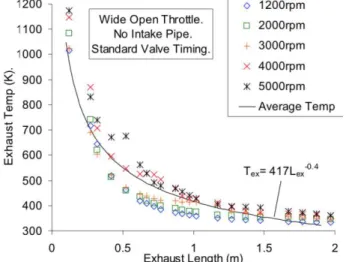
Exhaust tuning is highly dependant on its temperature and RPM range which can be seen in Figure 3, with an inverse relationship between the two. Unfortunately, exact temperatures of the exhaust will not be obtained until the engine gets dynoed in the upcoming Fall quarter. The figures shown are reference to a single piston, 4-stroke, 500cc engine.
As can be seen in Figure 2, small changes in pipe length contribute to sudden changes in volumetric efficiency.
Figure 2: Rel. Vol. Eff. vs. Exhaust length [m] for a 500cc Engine
Figure 3: Exhaust Temp vs. Exhaust Length for a 500cc Engine
12 Both of the textbooks used in Cal Poly’s Combustion Engine Design class (ME 444) [Ferguson][Heywood] show that efficiency improvements can be made by making to modifications the thermodynamic cycle. The amount of heat transfer from the combustion chamber is also expected to have an impact on the engine’s efficiency. These two concepts are explored in detail below.
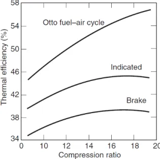
Large changes in engine performance through the manipulation of compression ratio, expansion ratio, and type of combustion (compression vs. spark ignition) are well documented. Of these, we consider only the compression and expansion ratio because of the difficulty of controlling gasoline compression ignition. Compression Ratios (see Compression Ratio): The compression ratio is the volume of the cylinder at the end of the intake stroke divided by the volume at the end of the compression stroke. Increased compression ratios lead to increased efficiency. For example, a compression ratio of ~17:1 results in a brake thermal efficiency of ~40% compared to ~35% at 9:1. The theoretical (Otto), realized (Indicated), and realized less frictional losses (Brake) efficiencies are plotted in Figure 4 (reproduced from Ferguson and Kirkpatrick).
Figure 4: Efficiency of a Spark Ignition Engine vs Nominal Compressino Ratio [Ferguson & Kirkpatrick Fig. 13.13].
The realized efficiency curves differ from the idealized Otto cycle for several reasons including:
• Mechanical friction – various sources for mechanical friction exist, chief among them are the piston rings. The magnitude of this loss increases with increasing engine speed.
• Pumping inefficiencies – the engine cannot complete fill the cylinder with fuel air mixture due to the finite time and valve area available.
• Finite time – heat addition and rejection cannot happen instantly at constant volume, therefore some efficiency is lost.
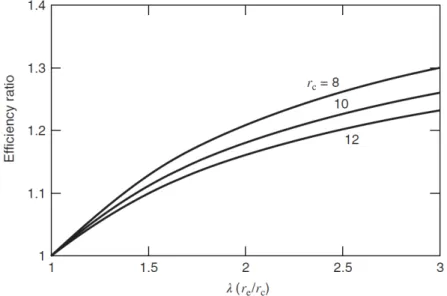
13 Expansion Ratios: The expansion ratio is the volume of the cylinder at the end of the exhaust stroke divided by the volume of the cylinder at the end of the compression stroke. An engine with a larger expansion than
compression ratio is described as being “over-expanded.” As seen in Figure 5 an expansion:compression
ratio of 2.5:1 netted a 25% efficiency gain over a 1:1 ratio.
Figure 5: Predicted Efficiency Ratio of an Over-Expanded Engine (Over a Standard Otto Cycle) vs. Expansion:Compressino Ratio [Ferguson & Kirkpatrick Fig 2.8].
However, increased expansion ratios reduce power production for a given cylinder volume. The same 2.5:1 expansion:compression ratio engine produced ~45% less power than one operating at a 1:1 ratio. This is because the effective volume of the cylinder – that is, the volume of air combined with fuel and combusted – is substantially reduced.
14 [Ferguson & Kirkpatrick Fig 2.9].
These types of engines operate on the “Atkinson” or “Miller” cycle (the later employing some kind of
forced induction in order to restore power density). These cycles are being emulated by some manufacturers through the use of modified valve timing (e.g. Toyota closes the intake valve after the beginning of the compression stroke on some engines) but we are not sure if the associated power density (power per engine weight) penalty is worth the increase in efficiency. If the power density is too low, then a larger engine will be needed to provide sufficient power. The larger engine will mean a heavier vehicle, which will need more power to get to the speed required, which will require a larger engine. This positive feedback will settle out eventually, but if we can have a smaller engine, then we will need less fuel. We anticipate that there will be a local minimum of the trade off between power density and expansion ratio, and suggest exploring these trends through the use of simulation tools.
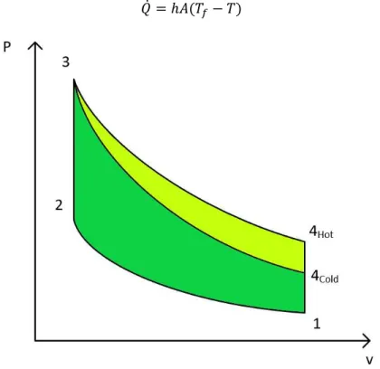
Heat Transfer: Additional efficiency can be gained by reducing heat transfer from the combustion chamber. This heat transfer represents an energy loss which could otherwise be used to accelerate the vehicle. As can be seen from the 2D equation for convective heat transfer, the rate of heat transfer is affected by the surface area:volume ratio of the cylinder, the engine operating temperature, and the time required for complete combustion.
𝑄̇ = ℎ𝐴(𝑇𝑓− 𝑇)
Figure 7: A qualitative PV plot of a typical Otto cycle (1-2-3-4Hot), and one for a cold engine (1-2-3-4Cold). The reduction in net work is shaded in yellow-green and is the area enclosed by (4Cold-3-4Hot). • Area:Volume ratio (see Bore:Stroke): Note that the amount of fuel burned is proportional to the
cylinder volume, but heat transfer is related to the surface area. Therefore a small area:volume ratio is preferred.
15 heat transfer). Will Sirski’s dyno testing investigated this effect. During interviews with our team he reported that efficiency was highly correlated with cylinder head temperature. Team ICE saw the same trend in the data (see Figure 8), but would like to collect additional data.
• Time: If the combustion can occur rapidly less heat will be lost. However, the flame speed of combustion is dependent on complex fluid dynamics.
Figure 8: Average BSFC vs. Average Engine Temperature (Calculated from Data Reported by Will Sirski)
However, it is important to realize that fundamental thermodynamics requires that a certain percentage of the energy must be rejected as heat. Team ICE anticipates that, on top of this lower limit, additional energy will be lost to engine warm-up. This additional loss is caused by increased heat transfer when the engine is cold (and therefore a high Tf – T term). This heat transfer will lead to a reduced cylinder pressure and reduced net work. A qualitative plot of this process vs. a typical Otto cycle process is presented in Figure 7. In order to minimize these losses and others, we will design and construct a system to maintain the engine temperature at its optimum over the anticipated burn-coast cycle.
To conclude, there are numerous methods for improving an engine’s efficiency through manipulation of its thermodynamic cycle and parameters relating to heat transfer. Many of these manipulations can be made by carefully selecting the engine’s geometry.
Compression Ratio
In the automotive racing industry, obtaining a relative high compression ratio is one of the ideal objectives for manufacturers. A compression ratio is a ratio where the maximum cylinder volume is compressed into the minimum cylinder volume. With a piston moving up and down inside of the cylinder, the lowest point of the piston is called the Bottom Dead Center where the cylinder volume is the highest. The highest point of the piston in the cylinder is called the Top Dead Center, where the cylinder volume is the lowest. Comparing the two volumes will output the compression ratio.
0.15 0.2 0.25 0.3 0.35 0.4 0.45
125 145 165 185 205 225 245 265 285
Av e ra ge BS FC [ lb m /H r/H P]
16 Air and fuel get compressed in the cylinder. Having an engine with a high compression ratio means that a given volume of air and fuel is being squeezed into a much smaller space than an engine with a lower compression ratio. Engine power is generated when combustion exerts a force on the piston, causing the piston to go down the cylinder during the expansion stroke. The higher the piston is in the bore when combustion starts, the greater the force that will be exerted. As the compression ratio increases, the piston travels higher in the bore at the top dead center meaning there is additional force for the same amount of fuel which equates to higher efficiency.
During the interview with Dr. Lemieux, he stated that there is a point of diminishing returns for an increased compression ratio; can’t increase it without bound. In an actual engine other processes which affect engine performance and efficiency will vary with changes in compression ratio, such as: combustion rate and stability, heat transfer, and friction. While the geometric aspect of compression ratio (ratio of maximum to minimum volume) is well defined, the actual compression and expansion processes in engines depend on multiple factors. These factors include valve timing details and the importance of flow through the valves while they are opening or closing (which depends on engine speed). While obtaining higher compression ratios is great, there are limits to how high compression ratios can be before efficiencies and mean effective pressures start to decrease in engines. In addition, the ability to increase the compression ratio is limited by the octane quality of available fuels and knock.
Bore to Stroke Ratio
During the interview with Will Sirski and Dr. Mello, we discussed several possible parameters that could affect the engine fuel efficiency based on the lessons learned from the competition. One of the parameters that have a significant impact on the fuel efficiency is engine’s bore to stroke ratio and therefore, the team decided to do background research on that topic.
Bore to stroke ratio is the ratio of the cylinder bore diameter and the length of the piston stroke. Smaller bore to stroke ratios reduces the surface are to volume ratio when the piston is at the top dead center. This reduces the heat loss from the combustion and improve the engine thermal efficiency. Smaller bore to stroke ratio also minimizes the flame travel distances and reduces heat release duration. These results will lead to a low performance but high fuel efficiency for the engine.
17 Figure 9: Plot of Net Indicated Efficiency at Three Different Bore to Stroke Ratios
Significant improvement in efficiency occur when it is reduced from the bore to stroke ratio of 1 to 0.83, but when the ratio is further reduced to .68, the data showed no further improvement. Although the flow enhancement is obtained from the additional decrease in bore to stroke ratio, this could lead to a greater cooling loss and hence no further increase in engine efficiency.
Air Starting Systems
During the Preliminary Design Review, Mr. Fabijanic brought up the possibility of using an electrically activated air starting system. We are concerned that this may be interpreted as not complying with the rules: “Article 64: Starter a) An electric starter must be used during the competition.”[Shell Eco-Marathon Rules]. We believe that it would be prudent to bring a back-up, electric only system to competition if an air-system is selected. In any case, we decided to take a preliminary look at air-starting.
Injecting compressed air into the cylinder is used in multi-cylinder engines, but we don’t see that as a viable strategy for this engine. There is only one cylinder, so it is forseeable that it would be difficult to build enough momentum in the flywheel by only pressurizing on the downstrokes. And pressurizing the crankcase to drive upstrokes would require additional valving (which carries a weight penalty), and likely a redesign of the crankcase seals and oil circulation pipe to tolerate the higher pressure.
Alternatively, an air-motor could be used in place of an electric starter. Air motors offer a high power density, which is certainly attractive. However, we think that the main issue with an air-starting system would be onboard compressed air storage. Modern batteries have achieved very good power densities, and we believe that a metal air tank would not compare well. Of course, if bump-starting would be used, then not much energy would need to be stored, and the power density of the air-starter may offest the losses in the tank. Another option to consider would be a composite tank.
18
Customers
The customers for this project are as follows: 1. Cal Poly Supermileage
2. Dr. Joseph Mello 3. ICE team Members
Cal Poly Supermileage team is the most important customer because the team is going to be the end user our engine selection. Our team had a meeting with Will Sirski, who was the engine lead for the Cal Poly Supermileage in 2019. After the interview, we learned about current engine related needs and available testing equipment. Another important customer for our team is Dr. Mello, who is our project sponsor as well as the faculty advisor for Cal Poly Supermileage team. Based on the interview with Dr. Mello, we were able to determine the project scope and the expectations from the sponsor regarding this project. Lastly, we also consider ourselves as customers because all team members will be working on the stages of designing, implementing and testing for this project. Using the information collected from these interviews, the team will come up with the list of needs that this project has to fulfill. The detailed list of the customer needs is attached as Appendix 1:.
Summary of Meetings/Interviews
Dr. Mello Interview
–
April 11
th, 2019
Efficiency and reliability were the main concerns that Dr. Mello brought up during our first meeting. He mentioned that the current Yamaha engine was not providing the same level of efficiency as the Honda engine (which the Supermileage team used previously). He wanted our team to research parameters that could affect the engine efficiency. He suggested possible research areas and what he learned from this year’s competition. With regards to the intake system, he mentioned that no other teams were using throttle bodies, and suggested that we investigate this and other intake and exhaust design choices. From this project, he expected that our team would be able to come up with a more efficient engine selection that could be handed off to the future engine subsystem for the Cal Poly Supermileage club.
In addition to some general guidelines, Dr. Mello made recommendations to the team about potential engines. The most discussed was the Briggs and Stratton Junior 206, which both Lavol and NIU are using to great effect. This also would allow the team to compete in the SAE Supermileage Competition. Mello also spoke of development into the Honda GX35, and suggested that the smaller displacement and much lower mass migh offset some of the power constraints with such a small engine. The compromise between the large and small engines is the current 50cc Yamaha engine being used by the team. All parties agree that this engine is overpowered and ineffective for the present vehicle and competition.
Will Sirski Interviews
19 In a subsequent interview with Will, he mentioned that the officials at the Shell EcoMarathon like to see clear starter disengagement from the engine.
Dr. Lemieux Interview
–
April 24
th, 2019
We consulted with Dr. Lemieux to make sure we did not miss any major areas of analysis and to get his impression of the areas with the biggest potential for gains to be made. Dr. Lemieux believes that the largest improvements will be made by managing the heat rejection from the engine. He recommended that we determine the steady state and transient (burn and coast) temperature distribution of the engine in the stock and modified configurations. Finally, he recommended that we avoid making a custom piston or cylinder head, and thinks that modifying the connecting rod is a more realistic goal. If we wanted to change the displacement of the engine, he thought a 'Frankenstein' approach (where components from one engine would be made to fit another) would have numerous advantages with regards to reliability and parts availability.
Objective
In this section, we present the problem statement and customer needs. Based on the customer needs, a QFD was created to scope out the project and brainstorm the possible modifications for the engine. Final product specifications were then generated to create a product that would be feasible and fulfill the customer needs.
Problem Statement
Team ICE strives to select and perform modifications which will result in an efficient and reliable engine that will compete in the Shell Eco-marathon. Our team will focus on improving efficiency without sacrificing reliability. To this end, we will design and build a thermal management system to maintain a selected engine temperature (which we will determine via dyno testing). Additionally, we will design and build intake and exhaust piping to minimize engine pumping losses, develop an electric starting system, and select and install an EFI/ESC system. We will also work with the new Cal Poly Supermileage engine team so that they are familiar with the engine and can continue development after the conclusion of our senior project. Finally we will work in the engines lab to benchmark the original engine and measure our progress from it.
Customer Needs
Team ICE met with customers and conducted interviews to determine their needs for our project. Using the customer statements from the interviews, the team came up with a list of requirements that this project has to satisfy. The list of requirements is tabulated and presented as Appendix 1. The requirements are sorted into similar categories that the team used as “Whats” for our QFD. A summary of the top three categories are described below:
20 the SMV, Dr. Mello directed Team ICE to select the Honda GX35 as the development platform.
Weight: Since the vehicle needs to go around the track, it is also important that it has the least weight since it will lead to lower fuel consumption. Moreover, a lighter engine will be easy to transport and assemble. This means that when designing components for the engine, our team needs to select materials and designs which accomplish the design goals with minimum weight.
Reliability: One of Dr. Mello’s main expectations is that our engine selection and modifications must be able to be passed onto the future engine subsystem team of Cal Poly Supermileage. Therefore, Team ICE needs to make the engine reliable as well as easy to operate and test.
QFD
ICE began developing the specifications for the new Honda GX35 engine by first completing a standard Quality Function Deployment (QFD). Refer to Appendix 2 for QFD. ICE used a number scale for the "Who vs. What" sections to identify the important relationship between the two. The scale is as follows: 5
for very important, 3 for neutral, and 1 for weak. ICE determined that the customers (“Who”) in this case
are the Supermileage Assembly, Drivetrain, Chassis/Aero, Engine teams, the Supermileage Driver, and Dr. Mello. We have considered Dr. Mello’s and the Engine team’s priorities first, and will aim to satisfy the other customers when possible. For the needs/wants ("What") we identified the following list as the most important: powerful, easy to install, small/compact, light, efficient, quiet, vibration, and reliable.
From the “Who vs. What” section we concluded that Dr. Mello wants a reliable, efficient, and sufficiently
powerful engine. In addition to those parameters, the engines team is somewhat interested in a quiet, and light engine which does not vibrate excessively. In general, all of the “Whats” had strong support amongst a few “Whos”.
Our next step in the QFD was to examine the competition’s and Cal Poly's engine designs. This proved to be difficult because competitors are not required to publish any information about their designs. We were able to find two papers: one covering an overhead cam cylinder head published by the Laval team, and a design overview from Northern Arizona University. Unfortunately these papers did not have all the information we needed. Fortunately, we were able to find more information in their marketing videos and material, but were unable to completely fill out the “Now” section of the QFD.
We moved on to the “How” and “How Much” sections in order to develop measurements of a successful engine design. Laval, BYU, and Canada UBC all run high compression ratios (from 12:1 to 17:1), low bore:stroke ratios (1:1.58 to 1:4) and low rpm (3000-5000RPM). This provided some confirmation of the trends we expected from our background research. The 1:4 bore:stroke ratio seems excessively high - we suspect that that engine runs on an over-expanded, Atkinson type, engine cycle.
21
Final Product Specifications
Table 1: Design Parameter Targets with their Associated Tolerances, Risks, and Method of Compliance
Parameter Description
Stock
Modified
Risk Compliance
1
Brake Specific Fuel
Consumption
0.6 lb/hr/HP
0.44 lb/hr/HP
H
A, T
2
Engine Power
1.3 HP
1 HP
H
A, T
3
Starter
Reliability
(# of Starts)
N/A
120
M
A, T
4
Volumetric
Efficiency
80%
(Estimate)
90%
M
A,T
5
Engine Control
Carburetor
and Fixed
Timing
EFI / ESI
M
I
6
Weight
7.6 lb
< 9.5 lb
L
A, T
7
Engine
Temperature
Cold
170
oF
M
T
Modifying the compression ratio is tempting, but because the Shell Eco-marathon only allows for 87 octane fuel, we expect this avenue to be severly knock limited. We have developed a test plan to rapidly evaluate this limit, and will thereafter determine whether the efficiency gain is worth the development time. Similarly, we expect that modifying the bore:stroke ratio will be difficult due to the limited availability of parts in the required sizes and their specialized alloys and construction. Therefore, we propose to modify the engine in order to reduce energy loss by heat transfer and pumping inefficiencies, and to maintain an efficient operating temperatue over the burn-coast drive cycle. These modifications will result in an engine specification better suited for the Shell Eco-marathon competitions (specifically: higher fuel efficiency). In addition, we will make several quality of life modifications including an electric starting system. We evaluated the risk of each of these modifications and have considered how we would predict and test their results. The modifications, risks, and method of compliance determination are listed in Table 1. Concept Design
22
Concept Generation
To avoid mental blocks during our initial ideation, we started with very general design goals. For the thermal system, we began with the idea of keeping warm items warm, but not too hot. Among others, we considered the techniques used in travel coffee mugs, winter athletic gear, and camping equipment. We then examined the engineering principles at work in each of the technologies. Each of the thermal systems limited heat transfer by conduction and convection in some way. Additionally, camping and athletic gear often provided some way to modulate the heat transfer through the use of vents, zippers, flaps, and other adjustments. We also noted that radiation might be an important heat transfer pathway due to the relatively high engine temperature.
Since the intake and exhaust have limited roles of inputting and outputting air to and from the engine, we generated ideas based on providing the best air flow. Starting with a stock intake we considered the curvatature of its pipe, whether we wanted it to be curved or linear based on the RPM range we wanted to work at. The next step was to incorporate a resonator to help resonate the frequencies of the incoming flowing air and the opening and closing of the intake valve to further increase the volumetric efficiency. Again, since the role of the intake is to input air, we generated concepts of the resonator based on the organ pipe analysis and helmholtz resonance analysis. For the exhaust, we considered a similar approach as the intake, but after more research it was determine that adding a resonator will be a little more difficult and the increase in volumetric will not be noticeable and in fact if it was not properly tuned, it will create a negative efficiency impact. We decided to go with a straight pipe that would be tuned to a certain length depending on the best operating temperature and RPM.
23 Our initial brainstorming session resulted in many interesting concepts (shown in Figure 9) including:
• An exhaust pipe which wrapped around the engine • Custom made vacuum insulation
• Actively controlling heat transfer • Hot oil pumping system
• Modular systems of rigid insulation panels
With regards to the engine starting system, we started our concept generation process after reading the competition rules and speaking with the SMV team. This directed our brainstorming session towards starting systems powered by electric motors. We also wanted to avoid the losses of constantly free-wheeling the starter motor. Some options we considered were:
• Solenoid starters (like those found in modern automobiles)
• Bendix starters (like those found in older automobiles and motorcycles) • Centrifugal or plate clutches
• Sprag or one-way bearings • The Honda OE clutch
Figure 11: Honda GX35 Clutch Mechanism.
24 We also spent some time investigating the different materials available for thermal management and gas piping. Some of the options we considered for the thermal system were:
• Aerogel • Mylar
• Aluminum Foil
• Fiberglass Exhaust Wrap • Ceramic Coatings
And for the gas piping systems we considered using: • 3D printed plastics
• Aluminum • Steels
Ideas for modification of the main engine parameters such as compression and expansion ratio were also considered.
A simple way to increase the compression ratio would have been to shave a head or block as one would in an automotive application. However, the Honda GX35 has a single piece head and block, so this option is not available to us. Other possibilities we raised include: offset grinding the crankshaft journals, making a custom connecting rod, piston, or crankshaft, or raising the crankshaft centerline up towards the valves. After doing some additional research, we discovered some online forum posts that claimed that a GX31 piston shared the same bore and wrist pin design as the GX35 but had a longer wrist pin to crown dimension. If true, this would be a low-cost way to increase the compression ratio.
Modifying the expansion ratio was also an attractive possibility. Major automotive manufacturers such as Toyota and Volkswagen accomplish pseudo-Atkinson cycles by varying the valve timing of the intake or exhaust valves. By holding them open part of the way through the compression stroke, they can reduce the effective compression ratio while holding the expansion ratio constant. Another possibility is to close the intake valve earlier than normal. A simple way to accomplish this might be through adjusting the cam timing, otherwise a custom camshaft, mid-operation cam timing variation, or some kind of camless valve acutation (Koeinsegg freevalve?) would be needed.
Concept Evaluation
In order to evaluate our initial concepts, we developed a list of functions that our final design must accomplish. We then selected quantitative and qualitative measurements with which we could judge our concept’s effectiveness.
The thermal management system’s primary function is to maintain the engine’s temperature within a range
25 The intake and exhaust systems must minimize the engine’s pumping losses. The exhaust system must also duct its gases to a place where they do not pose a hazard to the driver. Due to the intake port having a fixed diameter, increasing the mainifold diameter was not an option so the design of the resonator was the main priority in providing more air flow. The change in airflow into the cylinder occurs from the resonator to the cylinder so the length of the piping before the resonator depended on the design of the chasis and does not have an effect on the change of airflow.
The electric starting system should reach a good balance of efficiency, power, and lightness. Increasing the frictional losses of the engine is the antithesis of this project. Furthermore, if the starter can more quickly bring the engine to speed, fuel use during cranking might be reduced. Finally, the vehicle must also carry the starter with it. So a very heavy but efficient starter is not a good trade off, as the combustion engine will have to expend more fuel to accelerate it to speed.
All of the systems must withstand the vibrations transmitted from the road and engine, be affordable, and should be able to be purchased or manufactured within 15 weeks at Cal Poly.
From these functions we were able immediately set aside some of our initial concepts. An engine wrapped in an exhaust pipe would likely make maintenance difficult, be heavy, and may reduce the engine’s volumetric efficiency. Among other shortcomings, a fully controlled heat transfer system would be heavy when the control, power, and actuation systems are included. A sprag clutch or one-way bearing constantly meshed starter would increase frictional losses. Finally, many of the compression and expansion ratio changes would require advanced manufacturing and design which may not be feasible in the time remaining.
Thermal Management Structure Evaluation
26 Table 2: Decision Matrix for Thermal Management Structure
The criteria for the decision matrix is derived based on the QFD. The current concept (Concept A) is used as a datum because our thermal management structure need to be better than the current solution that has been implemented. Moreover, our design aims to reduce the space and make a compact structure in order to control the heat transfer. With the compact structure, the would be less heat loss via natural convection to the surrounding air. The decision matrix shows that Concept D has the highest score compared to the
datum. Concept D’s only disadvantage compared to the datum is the manufacturability. This is because the
structure of Concept D needs manufacturing a separate structure whereas the datum concept uses the structure of the vehicle as the thermal management structure. Concept D also offers opportunities to install some kind of active or passive venting if the engine temperature rises above the target.
Insulation Material Evaluation
27 Table 3: Decision Matrix for Thermal Insulation Material Selection
Figure 12: Radar plot associated with material selection decision matrix
In terms of the radar plots, there are clear winners on the material selection when designing around all factors. For example, aluminum foil offers low cost, high durability, and excellent radiative resistance in an easy to manufacture format. The radar plots also suggested some possible combinations of materials. For example, perhaps the aluminum foil's lack of conductive resistance could be mitigated by including some fibreglass in the design.
However, because the actual peak efficient temperature and heat retention is unknown for this engine, a determination cannot be made without further testing and analysis. The analysis done to this point (presented below) is based on assumptions that may prove inaccurate. While the above decision matrix may outline the benefits of each material in question, it is still unclear which of the requirements will be the driving factor. Therefore, a testing plan was developed to determine the effectiveness of each material. A sample of the testing plan is included in Appendix 5 for determining the effectiveness of a given option. First, material combinations which appear to be effective will be simulated in Ansys with our calibrated heat transfer model. Then, the best results from these simulations will undergo the same testing procedures. The results will be compared via a decision matrix for thermal density with respect to cost, thermal efficiency boost, and weight. Of the options, a final choice will be chosen based on trends in this empirical data
Because we are not yet sure what level of thermal resistance is required, we performed some preliminary heat transfer analysis. First, we wanted to determine the primary mode of heat transfer. We plotted the heat
Material Cost Conductive
resistance
Overtemp Risk (1 = High)
Radiative
resistance Durability
Ease of manufacture
Vacuum 2 5 1 1 3 2
Aerogel 1 5 4 1 1 2
Space Blanket (Mylar) 5 3 2 5 4 4
Thermal Wrap (Fibreglass) 4 4 5 1 5 4
28 transfer by convection and radiation from a unit area over a range of engine temperatures. As shown in Figure 12 radiative heat transfer accounts for at least 30% of the heat transfer starting at around 325oK. An initial estimate of the heat transfer rate from the engine was calculated based on percent of fuel energy lost due through various pathways (friction, heat losses, etc), the engine displacement, and the energy content of 87 octane gasoline. This estimate was then input into the Ansys model to provide an initial estimate for later calibration.
Figure 13: Heat Rejection by Convection and Conduction from Equivalent Surface Areas Using Reported Aluminum Material Properties and a Horizontal Fin Convection Coefficient.
Post-PDR feedback from Mr. Fabijanic suggested that ICE examine products such as HeatShieldProducts InfernoShield. This product is flexible, but holds its shape when deformed, and acts as a barrier to radiation and conduction. It can also be in direct contact with the heat source. There are many similar products such as header wrap, or other reflective barriers, however products like InfernoShield are both moldable and can withstand direct contact, whereas many other products can do or the other. However, we think that header wrap and an high temperature epoxy might be an affordable stand in.
Intake/Exhaust Evaluation
29 occurs near the max torque around the mid to higher RPMs. With the helmholtz theory, the volumetric efficiency was based on the size of the resonator (V2) relative to the combustion chamber (V1), as shown in Figure 13.
Figure 14: Intake with In-Series Helmholtz Resonator
With the helmholtz theory, a volume ratio of 10 between the resonator and cylinder yielded the highest volumetric efficiency in our interested range as shown below in Figure 14.
Figure 15: Volumetric Efficiency Curves for Different Volume Ratios
30 Figure 16: Plot of Torque and Horsepower vs. RPM
Table 4: Intake and Exhaust decision matrix Intake and Exhaust Ideation
Criteria Base Model Intake
Resonator Intake (Helmholtz)
Organ Pipe Intake
Straight Pipe Exhaust
Resonator Exhaust
Packaging 5 5 5 5 3
Manufacture 5 3 3 5 3
Tuning 3 5 1 1 1
Material
Options 3 3 3 5 3
Cost 3 3 1 5 3
Efficiency 1 5 1 3 3
Weighting 20 24 14 24 16
31
Electric Starting System
The design of the electric starting system has seen substaintial changes since the PDR report. Like many of the other concepts, the concept starting systems were evaluated using a decision matrix. In addition to selecting the type of clutch mechanism, we realized that small, 12VDC motors do not produce very much torque, and spin at rpms similar to the redline of the Honda GX35. Therefore, a reduction system of some kind will probably need to be employed.
The decision matrix for the engagement mechanism is presented in Table 5. A weighted decision matrix was used to place emphasis on the primary goal of efficiency. Reliability and repairability are grouped together because a very reliable design is less likely to need repair. However, some reliability issues might be acceptable if: the design is easily repairable, it’s failure is easily predictable, and it offers some advantage over a more reliable system. Clear disengagment was considered as a result of conversations with Will Sirksi, while design and fabrication efforts were considered due to the expanding project scope. Of the options considered, the Honda OE mechanism scores far ahead of the alternatives.
However, not all factors were considered in this decision matrix. The Honda OE clutch must rotate backwards a few degrees in order to disengage. Originally, this is accomplished with a clock spring which is separated from the power transfer. However, this would not be possible with an electric starting motor. During final design, significant difficulties were encountered when attempting to design a robust mechanism to perform this counter-rotation. Therefore, the second-place engagement mechanism (a one-way bearing) was selected for continued development. In order to comply with Shell Eco-Marathon rules, this will require that the clutch engagement RPM is above the maximum RPM of the starter motor.
Table 5: Starter Engagement Decision Matrix Cost Clear
Dis-engagement Frictional Losses Design & Fabrication Effort Reliability & Repairability
Weight Sum
Weight 3 3 5 1 4 5 -
Honda OE 5 5 5 4 4 5 96
One-way bearing
4 1 4 3 5 5 78
Bendix 2 3 5 2 3 5 73
Solenoid 2 5 5 2 3 4 77
Centrifugal 2 3 3 1 3 3 55
Bicycle Casette Sprag
5 1 4 2 4 5 77
32 Table 6: Starter Reduction Type Decision Matrix
Cost Efficiency Mounting Flexibility
Design & Fabrication
Effort
Reliability & Repairability
Weight Sum
Weight 3 5 2 1 4 5 -
Belt 4 3 5 3 5 4 80
Gear 3 4 2 4 4 4 64
Chain 4 3 5 3 5 4 85
From the decision matrix, the chain drive was initially selected due to excellent scores across the board. However, packaging issues meant that a sufficient reduction ratio was not possible with belt or chain drives without using a multi-stage system or a very large and complicated bracket. Therefore, a gear reduction system has been selected by team ICE.
Preliminary Concept Design
Our preliminary concept (less the starting system) is shown in Figure 17. The intake and exhaust systems can be seen in green, and the thermal management system is made transulucent to show the engine inside. Each of these systems will be discussed in detail in the following section.
33
Thermal Management
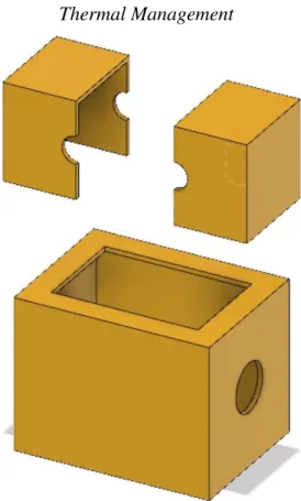
Figure 18: Preliminary concept model for the ICE thermal management system
The preliminary concept for the thermal management system is designed for maximum heat retention within an isolated area and is presented in Figure 18. This system combines the best of both worlds of two of the previous concepts: The insulated engine bay maintained a constant temperature along the entirety of the engine, but was too large of a volume of air to be efficient during the “burn-and-coast” cycle. The insulative wrap retained the heat well on the portions of the engine covered by the wrap, but allowed heat to escape from the numerous gaps in the insulation.
The model ICE has designed allows the heat rejection from the engine surfaces to the environment to heat up a very small volume of air. Effectively, the enclosure minimizes the “environment” making the net heat transfer required to increase the internal temperature low. This design also features semi-sealed ports, allowing the intake and exhaust piping to break the thermal barrier with minimal heat loss.
The concept also focuses on maintaining a system that is easily mounted and maintained in both the shop and track-side. This design features a two-step disassembly for rapid access to the critical components of the engine. The upper clamshells (Figure 20) are individually removable to allow access to the sparkplug, flywheel, intake/exhaust piping, and any sensors on the upper half of the engine for trackside maintenance and troubleshooting. The lower clamshell (Figure 19) provides the mouting surface to the vehicle, and can be easily removed for access to the engine oil, lower flywheel, and crankcase for more involved
34 Figure 19: The lower thermal management box features a thermal insulation to retain monoblock heat,
unimpeded output shaft, a retaining/sealing lip for the upper half, and a low emissivity coated surface
35 This model also allows for variation in the insulation medium. The close-formed clamshell will (without additional insulation) retain more heat in a closer proximity to the engine than the current aerogel-lined hood and will weigh substaintially less. Based on testing and analysis, if more heat retention is required for a more optimal thermal efficiency range, different insulation mediums can be applied, tested, and subsequently removed without difficulty.
Intake and Exhaust
To test our theory, our intake system is designed in the shape of cube so the bottom plate of the cavity is able to move up or down so the volume can be adjusted and test the volume ratio accordingly. From Figure 14 it can be seen that a volume ratio of 10 would be best suited for our RPM range, but with our current design we will be able to test more volume ratios. Our prototype will be made of Polyactide (PLA) for rapid prototyping since we have easy acces in campus and we can 3-D print it next quarter and start testing. The other option is ABS, but we do not have access to print ABS in campus and it will be more expensive if we have to do it outside of campus. Note, PLA does not have the best surface finish and it could a lot of loses due to friction. Our solution to this was to dip the intake into resin to have a softer finish that would be ideal to less frictional losses. For thermal management, the intake will be wrapped with header wrap to keep the air in the chamber cool from the cabin temperature. Colder air is more dense which means more oxygen for combustion as opposed to warm air from the cabin.
For the exhaust prototype we will be using stainless steel since it is easy to get and easy to adjust length for tuning. The only concern is that models investigated, the exhasut length was only slgihtly less than a meter long which would be a lot of material and will contribute to more weight. Once we know the operating temperature of the exhuast, we will be able to select from more materials to account for the length to weight ratio. We know that exhaust is highly dependant on temperarue and that higher temperature leads to lower exhasut length. In order to keep the exhaust length shorter, after we know the operating temperature and the length comes out to be long, the exhaust will also be wrapped in order to keep temperature high Figure 21 shows the prelimary design of the intake system with the Helmhotz resonator. As explained earlier, the design of the resonator was model as a box so we care able to adjust different volume ratio of the resonator to the cylinder. The bottom part of the resonator will consist of an adjustable plate that will be able to move up or down in order to test the different volume ratios.
36 Figure 22 shows the prelimary design of the exhasut pipe. Since the exhaust is highly dependant on temperature we decided to model the exhaust as a straight pipe and tune the exhaust to the correct length. A straight pipe sounded more resonable because the length of the pipe can be easily modified to investiage different lengths, avoid a negative change in efficiency. The overall theoretical efficiency increase was of only 5% compare to 12% of the intake so we aim to make the exhaust simpler and focus on the intake.
Figure 22: Preliminary design of exhaust pipe
Compression Ratio
Our team wanted to take advantage of the theoretical improvements offered by increasing the compression raito. However, we can’t find any information on the knock limit of the 87 octane fuel. We first considered testing a series of pistons with increasing compression ratios, but decided that the testing involved would be to time consuming. Additionally, from our conversations with Dr. Lemieux, and our team's experience with the manufacturing capability on campus, we felt that making a large number of custom pistons would put us in danger of falling behind schedule.
Instead, team ICE has decided to utilize off the shelf parts in order to investigate the compression limit and then follow up by purchasing or manufacturing a small number of pistons. We plan to do this by first installing a piston which will result in a very high compression ratio. Then, we will adjust the dynamic compression ratio (the realized compression ratio when the engine is running- e.g. not determined solely by volume ratio) until we reach the knock limit for an engine on a tune designed to maximize efficiency. The parts we plan to use include a Honda GX31 piston and the Honda GX35’s exhaust decompression system. The Honda GX31 piston has been reported by hobbyists to fit in the Honda GX35 engine using the GX35 connecting rod and crankshaft. The GX31 piston is reported to be taller from the wrist pin to the piston crown, meaning that there will be less clearance volume, and therefore a higher compression ratio. There are no drawings or specifications available to corroborate these claims, but the GX31 has the same bore as the GX35 (39mm) and the same wrist pin part number (13111-ZM5-000). Unforunately, there is conflicting information about piston-valve/cylinder head clearance. Some people claim that approximately 20 thousands need to be removed from the piston crown, others say that no material needs to be removed. In any case, a piston kit including rings and wrist pin is ~$30 online. We think the potential advantages and low cost make it worth trying.
37 for testing. This will allow us to adjust the dynamic compression ratio down from the geometric ratio (reported by hobbyists as 12.5:1). Note that this system may not work well for an Atkinson type cycle. Because the exhaust valve opens on the compression stroke, fuel will be pumped out of the combustion chamber without being combusted. We anticipate that this will lead to a large increase in BSFC, and may also represent a safety hazard (which we have accounted for).
Figure 23: Secondary Exhaust Cam Lobe in the Fully Deactivated (Left) and Activated (Right) Positions The approach outlined above will allow team ICE to quickly evaluate a series of compression ratios through easily made adjustments which are accesible from within the valve cover. Compared to an approach requiring several tests with different pistons, we anticipate a significant decrease in manufacturing, setup, and testing time.
Electric Starting System
Initially, design work was started with the goal of integrated with the Honda clutch. It essentially acts as an out-of-plane one way pawl clutch. The clutch is engaged by rotating the clutch drum faster than the crankshaft of the engine. To disengage the clutch, it must be rotated backwards roughly 45o.
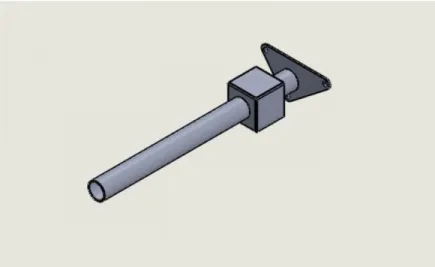
A new clutch drum (Figure 24) and bracket (Figure 25) were modeled, and AGMA calculations were done on a proposed gear reduction.
38 Figure 25: Early Starter Bracket Prototype
It was expected that machining the features on the top surface of the clutch drum would be difficult, so initial prototyping was to be done in ABS plastic. The lifetime of these parts was going to be evaluated through use on the dyno. If the lifetime was insufficient, some preliminary plans to produce all metal, or plastic/metal hybrid, clutch drums were drawn up.
However, achieving the 45o counter rotation proved to be more complicated than expected. Driver workload is already reported to be high by the SMV team, therefore we could not implement a two-button solution (push to start, push to disengage). Ideally, a circuit or mechanical device would implement this counter rotation. Coil, clock, or leaf springs could be inserted into the clutch mechanism, but some sort of detent or stop mechanism would be required to carry the starting torque. It would also create a delay between pressing the starting button and the begin of power transfer from the starter motor to the combustion engine. A 555 timer circuit was also investigated, but ICE has insufficient expereince designing these circuits, and did not have confidence in their design. Finally, a small microcontroller could be used – but this was judged to be a bit excessive.
The combination of the unknown lifetime of the plastic part, complex manufacturing, and difficult disengagement mechanism lead ICE to design a new starting system from the ground up. We still consider the Honda clutch to be a very advantageous design. It is lightweight, robust, and introduces zero frictional losses to the engine once disengaged. Therefore, we recommend that SMV further explore this solution once more information is known about starting loads and speeds.
In the meantime, a design using a one-way bearing and gear reduction is presented in the Final Design section: Electric Starting System.