Multi-Flow Scheduling for Coordinated
Direct and Relayed Users in Cellular Systems
Chan Dai Truyen Thai, Petar Popovski,
Senior Member, IEEE,
Megumi Kaneko,
Member, IEEE,
and Elisabeth de Carvalho,
Member, IEEE
Abstract—There are two basic principles used in wireless network coding to design throughput-efficient schemes: (1) aggre-gation of communication flows and (2) interference is embraced and subsequently cancelled or mitigated. These principles inspire design of many novel multi–flow transmission (MFT) schemes. Such are the Coordinated Direct/Relay (CDR) schemes, where each basic transmission involves two flows to a direct and a relayed user. Usage of MFT schemes as building blocks of more complex transmission schemes essentially changes the problem of scheduling, since some of the flows to be scheduled are coupled in a signal domain and they need to be assigned a communication resource simultaneously. In this paper we define a novel framework that can be used to analyze MFT schemes and assess the system-level gains. The framework is based on cellular wireless users with two-way traffic and it sets the basis for devising composite time-multiplexed MFT schemes, tailored to particular optimization criteria. Those criteria can be formulated by adapting well-known schedulers in order to incorporate MFT schemes. The results show rate advantages brought by the CDR schemes in pertinent scenarios. Another key contribution is the proposed framework, which can be used to evaluate any future multi-flow transmission scheme.
Index Terms—Wireless relay, wireless network coding, inter-ference cancellation, coordinated transmission.
I. INTRODUCTION
A. Motivation
W
IRELESS network coding has recently emerged as one of the key generic techniques that can boost the throughput performance of wireless networks. A canonical scenario that demonstrates the benefit of wireless Network Coding (NC) is the scenario with Two–Way Relaying (TWR). There are two basic principles used in designing throughput-efficient schemes with wireless network coding:1) Aggregation of communication flows. Instead of trans-mitting each flow independently, the principle of net-work coding is used in which flows are sent/processed jointly;
2) Embracing the interference that can be subsequently cancelled or mitigated.For example, in analog network
Paper approved by X. Zhang, the Editor for Wireless Networks and Tech-niques of the IEEE Communications Society. Manuscript received October 5, 2011; revised July 18, 2012.
This work is supported by the Danish Research Council for Technology and Production, grant nr.09−065035, and by the Grant-in-Aid for Scientific Research no.10595739from the Ministry of Education, Science, Sports and Culture of Japan.
C. D. T. Thai, P. Popovski, and E. de Carvalho are with the De-partment of Electronic Systems, Aalborg University, Denmark (e-mail: [email protected],{petarp, edc}@es.aau.dk).
M. Kaneko is with the Graduate School of Informatics, Kyoto University, Kyoto, Japan (e-mail: [email protected]).
Digital Object Identifier 10.1109/TCOMM.2012.120512.110669
x3
yR (x3, x4)
D R
x4
x3
x4
yR(x3, x4)
Sud
x1
yR (x1)
D R
x4
x1
x4
yR(x1)
h5 x3
yR (x2 ,x3)
D R
x2
x3
x2
yR(x2,x3)
Sdd Suu
x1
yR(x1) L B
D R
x2
x1 yR(x1)
h4
Sdu
x2
N
N N N
N
N N N
B L
B L
B L
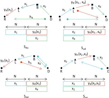
Fig. 1. Individual CDR Schemes Sdu, Sud, Sdd and Suu. In each
scheme, the time slot of the transmission represented by an arrow above is also represented by a rectangular below with the same dash style and the transmissions represented by the rectangles in the same column are conducted simultaneously. An interference signal is represented by an arrow with a thick end.
coding, flows are allowed to interfere, knowing a priori that the interference can be cancelled by the destination.
Using these two principles can give rise to novel transmission techniques. In [1], [2] we have shown that the communication flows of a direct and a relayed user can be jointly served, which can bring very visible performance benefits with respect to the reference (conventional) way of serving the same communication flows. The four schemes discussed in [2] are described on Fig. 1. Assume for example that a direct user wants to send a packet to Base Station (BS) B, while the BS has a packet to send to a relayed user. In a conventional cellular system, these packets are sent over separate UL/DL phases. Instead, as seen in scheme Sdu of
Fig. 1 the BS may first send the packet which is received at Relay Station (RS) L. While the RS forwards this packet to its intended relayed user, the direct user sends its packet to the BS, thus saving the required transmission time compared to the conventional method. We term such a schemecoordinated direct/relay (CDR)transmission scheme.
Despite the fact that each individual scheme from [2] brings throughput benefit with respect to the related reference schemes, the system-level aspects of these novel transmission
schemes remain largely unclear. In [2] there was a preliminary study on how the individual CDR schemes can be used as building blocks for scheduling schemes to serve multiple users. However, the multi–user scenario in [2] is rather limited and cannot provide satisfactory answers in comparing the CDR schemes with other state-of-the-art schemes, notably the two-way relaying [3].
One of the main objectives of this paper is to define a suitable framework for analyzing and comparing the multi– flow transmission (MFT) schemes, such as CDR and two– way relaying. Rigorously speaking, any time–division scheme in which e.g. the communication flows of multiple users are served in the downlink, is a MFT scheme. However, here we use the term MFT scheme to denote a transmission scheme in which the multiple flows are essentially coupled in the signal domain, they use the wireless medium simultaneously, and cannot be decoupled via time division. This is true, for example, for a two–way relaying scheme with wireless network coding based on amplify–and–forward [4]. That is an MFT scheme and the signal–domain coupling is seen in the fact that the achievable rate region is not the triangle obtained by time–division between two one–way relaying schemes.
In attempting to define the suitable analytical framework, we need to change the scheduling task from its usual definition (“at a given time, allocate the single communication resource to a certain communication flow ”) to a definition that can deal with MFT schemes (“at a given time, allocate the single communication resource to a group of communication flows”). With such prerequisites, the problem at hand can be defined as follows. Suppose that M flows should be served in a given scheduling epoch. In that case the performance of any proposed algorithm to serve these flows can be assessed by an M−dimensional achievable rate region. The central question that we will address is: how much can we enlarge the region of achievable rates if the algorithm that serves the flows can leverage on MFT schemes? In particular, we investigate the benefits of applying the CDR schemes.
The work in this paper treats the case in which any relaying operation is conducted by using amplify–and–forward. Using other relaying techniques may change the analysis and the conclusions, but, the analysis framework and the problem at hand, sublimed in the central question above, remains the same. This framework consists of scenarios and methods for combining MFT schemes into a single composite scheme that serves multiple flows. Another contribution is that we apply insights from practice in order to put constraints on the com-munication flows and restrict the analysis of the achievable rate regions to tractable, two-dimensional sub-regions. Finally, we consider multi–user scenarios for which we show how several canonical schedulers (Round Robin, Maximum Sum– Rate (Opportunistic Scheduler), Proportional Fair scheduler) can be formulated and applied when MFT schemes are used as building blocks for transmission.
Surveying the related work and regarding the combination of the transmissions of two users, transmission schemes that are somewhat related to the schemes treated in this paper have appeared before [5], [6], or to relayed users [7], [8]. In another aspect, regarding the joint resource allocation of uplink and downlink of a user, [9], [10] and references therein discuss that
the total amount of resource for uplink and downlink can be dynamically adjusted and the uplink and downlink satisfy the user as in a common service. In this paper, we jointly allocate uplink/downlink resources to different user types and analyze the rate performance under different scheduling policies. On the other hand, several advanced versions of TWR NC have been proposed e.g. the optimization of the different phase durations in TWR NC is considered in [12] and the space distribution of users is exploited to optimize the TWR NC scheme in [11]. Therefore in this paper, we treat TWR NC as a building block that represents the state-of-the-art.
The paper is organized as follows. Section II presents the network model of the paper. We present the individual schemes in section III. Section IV describes the composite schemes and presents the framework for analyzing the achievable rate region. Section V compares the reference schemes and CDR schemes using different schedulers while Section VI presents and analyzes the numerical results. Section VII concludes the paper.
II. SYSTEMMODEL
We first introduce the relevant notation and system concepts by considering a cellular network with one base station (B), one relay (L), one relayed user (R) and one direct user (D) see Fig. 1. The direct channel BS-R is assumed weak and R relies only on the amplified/forwarded signal from the RS in order to decode the signal from the BS. All transmissions are in one frequency with a normalized bandwidth of 1 Hz. All stations are single-antenna and half-duplexed. Each of the complex channelshij,i, j∈ {B, L, R, D}, is reciprocal, known at the
receiver. We assume all the channels are known at the BS as in [14], [15]. Each user requests an uplink and a downlink transmissions to the BS. We assume that the data to/from each user is infinitely backloggedso that there are always data to transmit as in many works regarding downlink [16] and Two-way Relaying optimization [17] and scheduling [18], [19]. Thus the achievable rate for a user at a certain time is equal to the information theoretic capacity, i.e.C(γ) = log2(1 +γ),
where γ denotes an instantaneous received signal-to-noise ratio (SNR) of the channel used. Therefore the maximal rate received at a station over channell is C(γl).
We use the following notation, with a slight abuse:xi may
denote a packet or a single symbol, and it will be clear from the context. For example, the packet that the BS wants to send to user R is denoted byx1; but if we want to express the
signal received, then we use expressions of typey=hx1+z,
wherey,x1 andz1denote symbols (received, sent and noise respectively). We introduce further notations:x4is the packet
sent from the BS to D, while the packets that the BS needs to receive are x3 from user R and x2 from D. x1, x2, x3
andx4 are therefore corresponding to 4 traffic types: relayed
downlink (Rd), direct uplink (Du), relayed uplink (Ru) and direct downlink (Dd) respectively. Throughout this paper, small u andd denote uplink and downlink while capitalized D andRdenote the direct and relayed users respectively. All relaying transmissions in this paper are Amplify-and-Forward (AF).
scheduling epoch. In this paper we will assume that in each epoch two users will be served, each having uplink/downlink traffic, which corresponds to four flows per epoch. If there are more than two users in the system, then two of them are selected according to a certain scheduling criterion and, again only four flows are served in an epoch. During a scheduling epoch several different transmission schemes can be multiplexed in time, including both MFT schemes and single–flow transmission (SFT) schemes. The part of the epoch during which a fixed transmission scheme is used is termed frame. While the duration of a scheduling epoch is fixed, the duration of each frame within the scheduling epoch is variable and subject to optimization. The transmission schemes corresponding to different frames will be introduced in the next section.
In an individual scheme, the received signal and Additive White Gaussian Noise (AWGN) at the BS, the RS, user R and user D in time slot j is denoted by yi[j] and zi[j] ∼
CN(0, σ2), i ∈ {B, L, R, D}, j ∈ {1,2}. The average
transmit power at all stations is 1, E[|s|2] = 1,sis a symbol
when transmission is done at the BS, user R or D,sis a relayed signal when transmission is done at the RS. At the RS, the received signal is scaled to comply with transmit constraint.
Regarding the notation, for a compact notation, we will write the matrices by using “;” to separate different rows of a matrix. For example, the2×nmatrix with1×nrow vectors
a1,a2can be written as [a1;a2]instead of
a1
a2
.
III. TRANSMISSIONSCHEMES: THEBUILDINGBLOCKS In this section we introduce the transmission schemes, where each scheme is a candidate to be used during a frame that is a part of a certain scheduling epoch. The candidate schemes are of two types, SFT schemes and MFT schemes. We first describe the four MFT schemes based on coordinated direct and relay (CDR) transmission. The other schemes that can be used in a frame feature conventional one–way direct and relayed transmission, as well as the two–way relaying. It should be noted that different transmission schemes corre-spond to different set of communication flows. For example, the first scheme, denotedSdu on Fig. 1 serves two flows, the
BS to user R and user D to the BS, respectively. Another scheme would be an SFT scheme in which only the flow user D to the BS is served - hence, the set of flows in this latter case is a subset, but not identical to the set of flows used in Sdu.
A. Multi–Flow Transmission Schemes with CDR
Each of schemes Sdu, Sud, Sdd, Suu combines two
communication flows, one associated with a direct and another with a relayed user, respectively. There are four possible flows associated with these two users, which we have already denoted as Dd, Du, Rd, Ru. Each of the four schemes is an MFT scheme that has a duration of 2N symbols. Sdu
combines Du and Rd, subscript du means that the relayed user (the first user) has a downlink message and the direct user (the second user) has an uplink message. Sud combines Dd and
Ru, Sdd combines Dd and Rd andSuu combines Du and Ru.
The time interval of 2N used by a given scheme is divided
into two time slots, each having N symbols. In each slot, one single transmission or two simultaneous transmissions are performed. The transmissions in each scheme are arranged so that the interference is reduced or cancelled. We present each scheme in details below.
1) Coordinated Scheme Sdu: BS transmits x1 to the RS
in the first slot, the RS receives yL[1] = hBLx1 +zL[1]
(Fig. 1). In the second slot, the RS scales the received signal with the amplification factor αSdu = |hBL|12+σ2 and transmits it. At the same time, D transmits x2. User R
therefore receives signalyR[2] =hLR√αSduyL[1]+hRDx2+ zR[2] =hLR√αSduhBLx1+hLR√αSduzL[1]+hRDx2+zR[2]
and the BS receives yB[2] = hBL√αSduyL[1] +hBDx2+ zB[2] = hBL√αSduhBLx1 +hBL
√
αSduzL[1] +hBDx2+ zB[2]. Since the BS knows x1 and all channels, it cancels
the component in x1 in yB[2], gets y˜B[2] = hBDx2 + hBL√αSduzL[1] +zB[2]and decodes x2 with SNR γDSdu =
|hBD|2 |hBL|2α
Sduσ2+σ2
= |hBD|2(|hBL|2+σ2)
2|hBL|2σ2+σ4 = γBD2γ(γBL+1)
BL+1 .User R decodes x1 treatingx2 as Gaussian noise with SINRγRSdu=
|hLR|2αSdu|hBL|2 |hLR|2αS
duσ2+|hRD|2+σ2
= γBLγLR
γBL+γLR+γRD+γBLγRD+1. We have the corresponding ratesRSdu
D = 12C
γSdu
D
andRSdu
R =
1
2C
γSdu
R
.
2) Coordinated SchemeSud: User R transmitsx3 and the
BS transmits x4 simultaneously in the first slot (Fig. 1).
The RS receives yL[1] = hLRx3 +hBLx4+zL[1] and D receives yD[1] = hRDx3+hBDx4+zD[1]. In the second
slot, RS scales the received signal with the amplification factor αSud =
1
|hBL|2+|hLR|2+σ2 and transmits it. The BS receivesyB[2] =hBL√αSudyL[1]+zB[2]and user D receives yD[2] = hLD√αSudyL[1] + zD[2]. Since the BS knows x4 and the channels, it cancels x4 component in yB, gets
˜
yB[2] =hBL√αSud(hLRx3+zL[1]) +zB[2]and decodesx3. At D,yD[1]andyD[2]form a virtual 2-antenna received signal
y = Hx+z, with y = [yD[1] yD[2]]T,x = [x4 x3]T,z=
[zD[1], hLD√αSudzL[1] +zD[2]]T, and
H=
hBD hRD
√
αSudhBLhLD √αSudhLRhLD
. (1)
We can apply the MMSE receiver as in [20] to have the rates RSdu
R = 12C
γBLγLR
2γBL+γLR+1
and RSdu
D =
1
2C
γBD(γBL+γLR+γLD+1)+γLD(γBL+γb2) (γRD+1)(γBL+γLR+γLD+1)+γLRγLD
.
3) Coordinated Scheme Sdd: BS transmits x1 in the first
slot, the RS relays it to user R and the BS transmits x4
simultaneously in the second slot (Fig. 1). The transmissions are yL[1] = hBLx1 +zL[1], αSdd = 1
|hBL|2+σ2, yR[2] =
hLR√αSddyL[1] +zR[2], yD[1] =hBDx1+zD[1], yD[2] = hLD√αSddyL[1] +hBDx4+zD[2]. User R decodesx1 from yR[2] without interference. At D, yD[1] and yD[2] form a
virtual 2-antenna received signal y = Hx+z, with y =
[yD[1] yD[2]]T,x= [x
4 x1]T,z= [zD[1]hLD√αSddzL[1] +
zD[2]]T, and H =
0 hBD
hBD √αSddhBLhLD
. We can
apply the MMSE receiver to have the rates RSdu
1
2C
γBLγLR γBL+γLR+1
and
RSdu
D =
1 2C
γBD(γBD+ 1)(γBL+ 1)
(γBL+γLD+ 1)(γBD+ 1) +γBLγLD
. (2) 4) Coordinated Scheme Suu: User R transmits x3 and
user D transmits x2 in the first slot. In the second slot,
the RS transmits what it received in the first slot (Fig. 1). The transmissions are yL[1] = hLRx3 + hLDx2 + zL[1], αSuu =
1
|hLR|2+|hLD|2+σ2, yB[1] = hBDx2 + zB[1], yB[2] = hBL√αSuuyL[1] +zB[2]. The BS decodes x2 and x3 from yB[1] and yB[2]. Similar to the previous
schemes, we havey=Hx+z, withy= [yB[1]yB[2]]T,x=
[x2 x3]T,z = [z
B[1] hBL√αSuuzL[1] +zB[2]]T, and H =
hBD 0
√
αSuuhBLhLD √
αSuuhBLhLR
. We can apply MMSE
receiver for both users to have the sum–rate. We have the rates RSdu
R = 12C
γBLγLR(γBD+1)
γBLγLD+(γBL+γLR+γLD+1)(γBD+1)
and
RSdu
D = 12C
γBD+γBL+γLR+γBLγLDγLD+γBLγLR+1
.
B. Reference Transmission Schemes
In this part we describe other transmission schemes that can be used to build a composite reference scheme. The motivation comes from the following: If a designer is not aware about the CDR schemes receives the task to serve M communication flows in a given epoch, which schemes are at his/her disposal? Clearly, the first candidates are the usual single–flow schemes, which we, for convenience, denote asSod,Sou,SdoandSuo.
SchemeSodis a one-hop transmission from the BS to user D
(Fig. 2). The BS transmitsx4 (Dd) and user D receivesyD=
hBDx4+zD and decodes x4 with the maximal achievable
rate of RSod
D = C(γBD). In scheme Sou, user D transmits x2 (Du) and the BS receives. Similarly, we have the same
maximal achievable rate of RSou
D = C(γBD). In schemeSdo,
first the BS transmitsx1(Rd), the RS receivesyL=hBLx1+ zL, amplifies with amplification factorαSdo=
1
|hBL|2+σ2 and transmits. User R receives and decodes x1 with the maximal
achievable rate ofRSdo
R = C
γBLγLR γBL+γLR+1
. The transmission in the opposite direction (Ru) is conducted in schemeSuo. We
have the same maximal achievable rateRSuo
R =RSRdo.
As a part of the reference transmission schemes, we con-sider theTWR NC based on AF. In accordance with the other schemes, this will be denoted STWR and it consists of the
transmission from the BS to user R (Rd) and the transmission from user R to the BS (Ru) using TWR NC (Fig. 2). First, in the Multiple Access phase, the BS and user R simultaneously transmit x1 (Rd) and x3 (Ru) respectively in N symbols,
the RS receives yL = hBLx1 +hLRx3 +zL, amplifies it
with amplification factor αSTWR =
1
|hBL|2+|hLR|2+σ2 and transmits it in the Broadcast phase in N symbols. User R receives, cancels the contribution ofx3 and decodesx1 with
SINR γSTWR
d = γBLγBL+2γγLRLR+1. The BS receives, cancels the contribution of x1 and decodes x3 with SINR γuSTWR =
γBLγLR
2γBL+γLR+1. We have the rates corresponding to the relayed uplink and downlinkRSTWR
u =
NCγSTWR u
2N = 12C
γSTWR
u
andRSTWR
d = 12C
γSTWR
d
.
x3
yR (x3)
B L
D R
x4
x4
x2
Sod
N 2N
x2
Sod
Sou
x1
yR (x1)
Sdo
Suo
Sou
x1
N yR (x1)
x3 yR (x3)
Sdo
Suo
yR (x1, x3)
B L
D R
STWR
N x1
x3
STWR
N x3
x1 yR (x1, x3)
Fig. 2. Individual schemesSod, Sou, Sdo, SuoandSTWR.
IV. MULTI-FLOWFRAMEWORK FORANALYZING THE ACHIEVABLERATEREGION
A. Composite Transmission Scheme with Time Multiplexing
Having introduced the individual transmission schemes, we now discuss the key element of the framework for analyzing the system–level performance improvements brought by the CDR schemes. The same reasoning can be used for any other proposal of a multi–flow transmission scheme. The first assumption is that each user has two–way traffic and both flows are backlogged with packets. The scheduling task is now defined as follows. In a given scheduling epoch, one direct and one relayed user are served, each with two way traffic. Determine how to multiplex the nine transmission schemes in time within the epoch in order to serve the users by optimizing a certain criterion. The concrete criterion can vary, e. g. optimize the sum rate under the constraint of equal rates between the direct and the relayed user, etc. We will discuss such criteria in the upcoming sections. Note that this framework represents a meaningful, but non-obvious way to compare the proposed schemes since e. g. direct comparison betweenSud andSTWR does not make sense.
The reader might object that this definition of the scheduling task is restrictive, as it uses the constraint that, in a scheduling epoch, we select one relayed and one direct user, but not e. g. two relayed users. Indeed, this definition is tailored to the structure of the proposed CDR schemes and fits our needs to investigate the gains brought by these schemes over the reference schemesSod, Sou, Sdo, Suo, STWR. If we allow
to schedule two relayed users in a given epoch, then these users would be served by time multiplexing of the schemes Sdo, Suo, STWR, without involving the CDR schemes. Clearly,
one can propose a MFT scheme in which the flows of two different relayed users are coupled, similar to the CDR schemes. However, such schemes are outside the scope of this work. On the other hand, the approach that we present here can be easily extended to analyze any new scheme that couples two or more flows of two or more relayed/direct users or any combination of them.
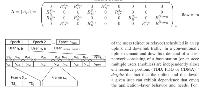
More formally, in a given epoch of duration T the indi-vidual scheme Si, Si, i ∈ {du, ud, ..., TWR}, occupies a frame of duration θiT, where the sum of fractions satisfies 9
i=1θi = 1 as shown in Fig. 3. The performance of the
A={Aij}=
scheme number ⎛
⎜ ⎜ ⎜ ⎝
−−−−−−−−−−−−−−−−−−−−−−−−−−−−−−−−−−−−−−−−−−−−−−−−−−→
0 RSud
D RSDdd 0 RSDod 0 0 0 0
RSdu
D 0 0 RDSuu 0 RSDou 0 0 0
RSdu
R 0 RSRdd 0 0 0 RSRdo 0 RSdTWR
0 RSud
R 0 RRSuu 0 0 0 RSRuo RSuTWR
⎞ ⎟ ⎟ ⎟ ⎠ ⏐ ⏐ ⏐ ⏐ ⏐ ⏐ ⏐ ⏐
flow number (3)
Epoch 1
TS1
Sdu Sud Sdd Suu Sod Sou Sdo Suo STWR ѳdu ѳud ѳdd ѳuu ѳod ѳou ѳdo ѳuo ѳTWR
TS2
Epoch 2 User i1, j1 User i2, j2
... Epoch nmax
User inmax, jnmax
(a)
(b)
(c)
Frame Sdu Frame Sod
Fig. 3. (a) The transmissions are organized as in epochs with the same durations, (b) An example of an epoch conducted inSall, (c) Examples of
two-slot frame ofSduand one-slot frame ofSod.
vector r = [RDd RDu RRd RRu]T = [R1 R2 R3 R4]T,
corresponding to the four communication flows Dd, Du, Rd, and Ru, respectively. We will use the notation R1 and RDd
interchangeably, also for the other three flows. The total rate achieved by a given flow in the scheduling epoch consists of contributions from each of the individual schemes that serves that flow, e.g.RDuhas contributions fromSdu, Suu, Sou. For a compact representation, denote A as in (3) in which the element at row i and column j is the rate contribution from the individual schemeSj, j∈ {du, ud, dd, uu, od, ou, do, uo,
TWR}which is equivalent to column 1, 2, ..., 9 respectively, to thei−th flow (Ri, i∈ {1, ...,4}). Hence, the four-dimensional
region of the rates that can be achieved by the composite scheme is described as 04 r Aθ where 0p or 1p is
the column vector [0, ...,0]T or [1, ...,1]T with p elements. The operator implies that for each vector component ≤ is satisfied. The region is obtained by varying θ such that
09θ19 and1T9 ·θ= 1.
The reference combined scheme Sref consisting of only
reference individual schemes is a special case of Sall when θdu =θud= θdd =θuu. Similarly, we have CDR composite
schemes Sduud when all θi = 0 except θdu, θud and Sdduu
when allθi= 0exceptθdd,θuu. WhileSallis the multiplexing
of all defined reference and CDR schemes, SCDR is the
multiplexing of all CDR schemes andSref is the multiplexing
of all reference schemes. In the following parts, we will analyze and compare these composite schemes; the gain by the CDR schemes is seen in the enlarged rate region offered by Sall compared toSref.
B. Rate Analysis with Uplink/Downlink Coefficient
A comprehensive analysis of the achievable rate region for the composite transmission scheme involves consideration of four–dimensional regions, which is not always tractable or sufficiently informative. In order to collapse the rate region to subregions of practical interest, we resort to the features of the communication flows served in an epoch. By assumption, each
of the users (direct or relayed) scheduled in an epoch, has both uplink and downlink traffic. In a conventional approach, the uplink demand and downlink demand of a user in a wireless network consisting of a base station (or an access-point) and multiple users (mobiles) are independently allocated in differ-ent resource portions (TDD, FDD or CDMA). This happens despite the fact that the uplink and the downlink traffic of a given user can exhibit dependence that emerges from e.g. the application–layer behavior and needs. For example, the downlink/uplink ratio is often fixed and depends on the type of application e. g. gaming and calls have ratio of 1:1, web browsing has a ratio of about 5:1 [13]. Generally, we can assume that the downlink rate demand and the uplink rate demand of a user satisfies, as in [10], Ri,d = βiRi,u, i ∈
{R, D},whereβi is termeduplink/downlink ratio (UDC)for
the i−th user.
We assume that the traffic demands by the i−th user are posed by specifying the UDC, defined as follows. In a certain scheduling epoch, all uplink/downlink flows of users are served and the rates are selected such that UDC is achieved for each of the served users. More formally, let
(RD,i(n), RR,i(n))be the downlink/uplink rates achieved for the i−th user in n−th scheduling epoch. Then with any n,
Rd,i(n) Ru,i(n)=βi.
In the following we analyze the rate region under the UDC constraints for the composite scheme Sall, let us represent
the matrix A as A = aT1;aT2;aT3;aT4 where e.g. aTp is the p-th row of A in (3). We are now interested in getting the bound for the two-dimensional vector that contains only the downlink rates rd= [RDd RRd]T. Let the corresponding
vector of uplink rates beru = [RDu RRu]T, such that rd=
βD 0
0 βR
ru.
Considering the direct user, if aT
1θ ≤ βDaT2θ, we select RDd = aT1θ and RDu = a
T
1θ
βD . If a T
1θ > βDaT2θ, we
select RDd = βDaT2θ and RDu = aT2θ. Thus RDd =
minaT
1θ, βDaT2θ
. RRd is derived similarly. Now the two
dimensional region is determined by:
0rd
minaT
1θ, βDaT2θ
,minaT3θ, βRaT4θ
T
. (4) To see how the rate region looks like we consider the simple case of Sduud. In this case, θdd = θuu = ... = θTWR = 0 and θud = 1−θdu. Replacing θ with [θdu,1− θdu,0,0,0,0,0,0,0]T andAin (3) to (4), we have
0rd
minRSud
D (1−θdu), βDRSRduθdu
,
minRSdu
R θdu, βRRRSud(1−θdu) T
. (5)
RDd RRd
Oc Od
Oa (θa) Of
Ob(θb)
Sall Sduud
Fig. 4. Demonstration of the rate region ofSduud.
m1=βDR Sdu D RSud
D
andm2=βRR Sud R RSdu
R
, we have.
• The first case is when RSud
D (1−θdu) ≤ βDRSRduθdu
andRSdu
R θdu ≤βRRSRud(1−θdu). This is equivalent to 1
m1+1 ≤θdu≤
m2
m2+1. The rate region is now determined
by 0rd
RSud
D (1−θdu), RSRduθdu
T
.If
1
m1+ 1
≤ m2
m2+ 1,
(6)
the diagonal upper bound of this rate region part is a line segment with equation RDd = RSud
D −
RSud D RSdu
R
RRd with
two ends determined byθa = m11+1 and θb= mm2+12 as
seen in Fig. 4. If (6) is not satisfied, there is not any valid value ofθdu.
• The second case is whenRSud
D (1−θdu)> βDRSRduθdu
andRSdu
R θdu ≤βRRSRud(1−θdu). This is equivalent to
0 ≤ θdu < θa and the rate region is now determined
by0 rd
βDRSRduθdu, RSRduθdu
T
. Both RDd and
RRd increases with θdu and the line segment OOa is
determined.
• The third case is when RSud
D (1−θdu) ≤ βDRSRduθdu
andRSdu
R θdu > βRRSRud(1−θdu). This is equivalent to θb< θdu≤1 and the rate region is now determined by
0 rd
RSud
D (1−θdu), βRRSRud(1−θdu)
T
. Both RDd andRRd decreases withθdu and the line segment OOb is determined.
• The forth case is when RSud
D (1−θdu) > βDRSRduθdu
andRSdu
R θdu > βRRSRud(1−θdu). This is equivalent to
m2
m2+1 < θdu< 1
m1+1. If (6) is not satisfied, the diagonal upper bound of this rate region part is a line segment similar to case 1. If (6) is satisfied, there is not any valid value ofθdu.
If (6) is satisfied, the first three cases determine a triangle in which if we decrease RRd of point Oa correspondingly,
we get the segment OaRDd,1 and if we decrease RDd of
point Ob correspondingly, we get the segment ObRRd,2. The
convex rate region is therefore formed as in Fig. 4. If (6) is not satisfied, the last three cases form a similar rate region.
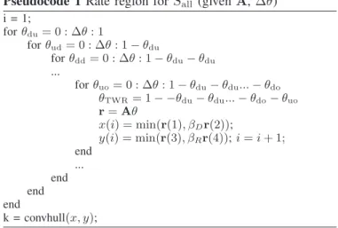
The rate region of scheme Sall can be found by the algorithm described through the Pseudocode 1 in which k is the index vector of the outer points of all achievable rate pairs
(x, y).
Pseudocode 1Rate region for Sall (givenA,Δθ)
i = 1;
forθdu= 0 : Δθ: 1
forθud= 0 : Δθ: 1−θdu
forθdd= 0 : Δθ: 1−θdu−θdu ...
forθuo= 0 : Δθ: 1−θdu−θdu...−θdo
θTWR= 1− −θdu−θdu...−θdo−θuo
r=Aθ
x(i) = min(r(1), βDr(2));
y(i) = min(r(3), βRr(4));i=i+ 1; end
... end end end
k = convhull(x, y);
V. MULTIPLE-USERSCHEDULING
Considering a pair of one direct user and one relayed user with four traffic types (Dd, Du, Rd and Ru), we have collapsed the four-dimensional rate region to two-dimensional rate re-gion by introducing UDCs. A natural question is what are the multiple-user schedulers that need to be used? In the following we describe how three commonly used schedulers can be adapted to the scheduling task defined in this paper: Round Robin with Equal Rates (RR ER) (Opportunistic Scheduler), Maximum Sum-Rate (MSR) and Proportional Fairness (PF).
We will make an additional distinction among the multi-user schemes. The composite schemes Sall, SCDR,Sref will
be termed multi-user-epoch (MUE) schemes since two users are served in each epoch. As a reference, we consider single-user-epoch (SUE) schemes, in which a single user is served in an epoch. Thus, SUE is a composite scheme which in a given epoch can be either multiplexing of Sod, Sou (if the user is
direct) orSdo, Suo, STWR, if the user is relayed.
A. Round Robin with Equal Rates
In order to emulate the original concept of round robin, here the two users (direct, relayed) are selected not based on the channel gains or achievable rates, but arbitrarily (e.g. by user ID). Without losing generality, we can say that in the first epoch the scheduler picks the first direct user and the first relayed user to make a pair and apply the composite CDR scheme. However, differently from a single–user scheduling schemes, here we have additional degrees of freedom also after the users are selected. These degrees of freedom are instantiated by changing the time–sharing vector θ. In order to further restrict the rate region, one possibility is to selectθ such that the downlink rates of the direct and the relayed user are equal. Recall that the uplink/downlink rates are related via UDC, such that the uplink rates of these users will have a ratio ofβD:βR. In the next epoch, that user pair is put aside
and the second direct user and the second relayed user are selected. If there are nD direct users and nR relayed users,
the number of such epochs is min(nD, nR). After that the
scheduler picks the next direct user (ifnD> nR) or the next relayed user (ifnR> nD) to serve as a single user in the next
two-user epoch described before. In order words, two direct users or two relayed users are put into a two-user epoch strictly divided by 2. Consequently, the number of two-user epochs in a scenario is k
2 , in whichx is the nearest integer≥x,
regardless of how many direct users and relayed users there are.
For a certain user pair and considering the UDCs, we have the conditions RDd = RRd, RDd = βDRDu and
RRd =βRRRu. In other words, we have to select θ so that
the schemeSm, m∈ {all,CDR,ref, ...}can provide the rates
for Dd, Du, Rd and Ru with ratio1 :β1 D : 1 :
1
βR. Considering the direct user and reasoning as in part IV-B, we select RDd= min
aT
1θ, βDaT2θ
andRRd= min
aT
3θ, βRaT4θ
. Since RDd =RRd, we select the maximum among different
θ as in (7) in whichRSm
(i,j)p andaT(i,j)q are the rate of traffic
type p, p ∈ {Dd, Du, Rd, Ru} and the q-th row of the matrix A corresponding to the user pair (i, j) offered by scheme Sm respectively and θm is the time segment ratio
vector corresponding to scheme Sm, e.g.SCDR has a vector
ofθCDR= [θdu θud θdd θuu 0 0 0 0 0]T. This problem is to
find an optimal vector θm which gives the highest downlink rates for a selected user pair. The procedure continues until all users are served as described above. After all user pairs are served, either only direct or relayed users are left, which are served through SUE. The average downlink rate offered by CDR with RR ER can be worse than that of SUE with RR ER, since the equal rate constraint limits the rate of the stronger user. This will be examined and discussed in the section with Numerical Results.
B. Maximum Sum-Rate
The Maximum Sum-Rate scheduler always selects the pair with the highest sum-rate to serve considering UDCs. The achievable downlink rate of direct user i is
minaT
(i,j)1θ, βDaT(i,j)2θ
and the achievable downlink rate
of a relayed user ismin
aT
(i,j)3θ, βRaT(i,j)4θ
. Therefore the user pair selected in an epoch favors the users with good channels and is described as in (8).
C. Proportional Fairness
In this part we use Proportional Fairness (PF) [18], [22]– [24] as a metric for selecting a user pair in an epoch. In an epoch, PF selects the user with the highest ratio of its instantaneous rate and its average rate to serve. In the following, we consider UDC with PF which is long-term. This is viable because PF is actually related to the competition of flows from different users, while the UDC requirements capture the relation between the flows belonging to the same user.
The average rate of useriat the beginning of sessiont+1if during epocht, useriis provided a rate ofRi(t)isR¯i(t+1) =
0 if t = 0and R¯i(t+ 1) = ne−ne1R¯i(t) + n1eRi(t) if t >0.
Here, by user rate, we refer to his downlink rate and ne is
the number of epochs. Its uplink rate is scaled down by a corresponding ratio βD orβRdue to UDCs.
Normally, in a PF scheduler, at a certain time, only one user, which has the highest PF, is selected. However, there are some proposals for a scenario in which several users can
be selected at the same time since there are several available resource portions such as in OFDM system where there are several sub-carriers which can be assigned to different users at the same time. Among those, [23] proved that a scheduler is proportionally fair for a multi-carrier transmission system if and only if it satisfies
P = arg max
S
i∈U
1 + Ri(t)
(ne−1) ¯Ri(t−1)
(9)
in which S is any scheduler, U is the considered user set, Ri(t) is the total rate provided to user i at session t, and
¯
Ri(t−1) is the average of useri after the previous session.
In our case, we have to select two users in an epoch, therefore we can treat our scenario as an OFDM system with two sub-carriers. Thus the product in (9) has only two factors. The downlink rate provided by a composite scheme to a user can be seen as the rate a user can achieve when using a certain sub-carrier. The difference is that we cannot select two direct users or two relayed users and the resources are not fixed as the sub-carriers in OFDM but optimized using another degree of freedom.
Here in each epoch we select two users thus when we consider a user pair, the current rates of other users are 0. In a session, the achievable downlink rates of a direct user and a relayed user in the user pair(i, j)areminaT1θ, βDaT2θ
andminaT3θ, βRaT4θ respectively. Therefore the user pair
selected in an epoch according to PF is given in (10).
VI. NUMERICALRESULTS A. Two-User Scenario
In this section we calculate the rate region for a two-user scenario with fixed channels. Fig. 5 shows the down-link rate regions(RDd, RRd)of different combined schemes
Sall (all schemes), Sref (all conventional schemes), Sduud
(CDR schemes 1 and 2), Sdduu (CDR schemes 3 and 4)
and SCDR (all CDR schemes) in case of channels γ¯ =
[γBL γLR γBD γRD γLD ] = [10 10 10 −10 10]dB and βR = βD = 4. To calculate the rate region, the values of
θi, i ∈ {du, ..., TWR} use resolution Δθi = 0.08. The
rate region of Sall certainly contains all of the other rate
regions because it is the general case consisting of all value ofθi, i∈ {du, ..., TWR}.
The rate region ofSCDRis larger than the union of the rate
regions of SduudandSdduu while the rate regionSall is also
larger than the union of the rate regions of SCDR and Sref.
This is because θm has to be selected such that UDCs are satisfied.SCDR provides almost equal rates for the direct and
relayed users while Sref provide a low rate for the relayed
user by prioritizing the direct user. This is because the CDR schemes feature joint transmissions which contribute to the rates of both users.
B. Multiple-User Scenario
In this section we calculate the average downlink rate and the PF coefficient for users with randomized positions in a network. In the simulation, we runniteration= 1000scenarios.
(io, jo) = arg maxθminRSm
(i,j)Dd(θ), βDR Sm
(i,j)Du(θ), R Sm
(i,j)Rd(θ), βRR Sm
(i,j)Ru(θ)
= arg maxθminaT
(i,j)1θm, βDaT(i,j)2θm, aT(i,j)3θm, βRaT(i,j)4θm
(7)
(io, jo) = arg max
i,j∈Umaxθ
minaT
(i,j)1θ, βDaT(i,j)2θ
+ minaT
(i,j)3θ, βRaT(i,j)4θ
(8)
(io, jo) = max
i,j∈Umaxθ ⎛
⎝1 +min
aT
(i,j)1θ, βDaT(i,j)2θ
(ne−1) ¯Ri(t−1)
⎞ ⎠
⎛
⎝1 + min
aT
(i,j)3θ, βRaT(i,j)4θ
(ne−1) ¯Rj(t−1)
⎞
⎠ (10)
0 0.5 1 1.5 2 2.5
0 0.2 0.4 0.6 0.8 1 1.2 1.4
Direct downlink (bps)
Relayed downlink (bps)
S
all
Sref S
duud
S
dduu
S
CDR
Fig. 5. Simulation results of rate regions ofSall,Sref,Sduud,Sdduuand SCDRwithγ¯= [γBLγLRγBDγRD γLD] = [10 10 10 −10 10]dB andβR=βD= 4.
of R = 1. The BS is at the center of the cell which is also the origin of the coordinate system O(0,0). 4 relay stations are placed at the angle φ = 0, π2, π, 32π respectively and away from the BS with a normalized distance of Rr = 0.7.
A user is determined to be a direct user if it is inside the circle with center at O and radius of Rr = 0.7 as a similar
principle in [21]. Any other user is determined as relayed user, attached to the nearest relay station. The number of direct usersnDand the number of relayed usersnR=k−nDare not
necessarily equal. All channels are modeled as h= √hf dpl in whichhf is a Rayleigh fading coefficient with varianceσf =
1, dis the distance between the transmitter and the receiver and path loss coefficientpl= 3. We compare the performance
of the composite MUE schemes Sm, m ∈ {all,CDR,ref}
and composite SUE considering different schedulers RR ER, MSR and PF.
In a scenario, there arene= 200epochs. In an epoch with
RR ER scheduler, a user pair or a single user is served. After that a new pair or user is selected until no user is left. If a user pair is selected, the linear optimization problem presented in V-A is solved to find the optimal θm. The rates will be
calculated accordingly based on the formulas in sections III, V. If a single user is selected, since all channels are reciprocal and therefore the maximal downlink rate and maximal uplink rate are the same for both users, the single-user epoch is divided
-6 -4 -2 0 2 4 6
0 0.5 1 1.5 2 2.5 3 3.5 4 4.5 5
Uplink/Downlink Ratio (dB) (βD = βR)
A
v
erage downlink rat
e
(bps)
MSR S
all
MSR S
CDR
MSR S
ref
PF S
all
PF S
CDR
PF S
ref
PF S
SUE
RR S
all
RR S
CDR
RR S
ref
Fig. 6. Average downlink rate of some composite schemes with different uplink/downlink coefficients when different schedulers are used.
into two parts with ratio βi : 1, i ∈ {D, R}. In an epoch with MSR scheduler, the user pair which has the highest total downlink rate provided bySmis selected.
In an epoch with with PF scheduler, a time fraction vector which can maximize the PF coefficient as defined in (10) using a composite schemeSmis determined for each relayed-direct user pair. The pair with the highest maximum PF coefficient is selected. In case of SUE, the user with the highest maximum PF coefficient is selected as io= arg maxi∈U Rr¯ii in whichU
is the user set, ri, R¯i are the provided rate and average rate
of useriin an epoch.
The average downlink rate of all users when different composite schemes and different schedulers are used is shown in Fig. 6. In this simulation, all downlink rates of all users are summed up and divided by the total time used by all users in a given scenario. For each of schedulers RR ER, MSR and PF, the order from the best to the worst is Sall, SCDR, Sref and SUE. SUE performs worse than Sref does since it
lacksSTWR. As expected, the MSR scheduler has the highest
sum rate, while the PF scheduler is better than the RR ER scheduler because it tries to maximize the network rate taking into account the PF coefficient.
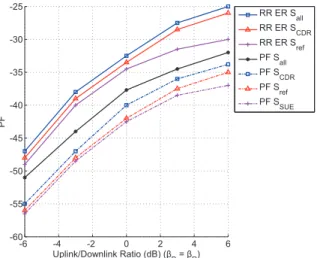
-6 -4 -2 0 2 4 6 -60
-55 -50 -45 -40 -35 -30 -25
Uplink/Downlink Ratio (dB) (βD = βR)
PF
RR ER S
all
RR ER S
CDR
RR ER S
ref
PF S
all
PF S
CDR
PF S
ref
PF S
SUE
Fig. 7. PF ofSall,SCDR,Sref and SUE with different uplink/downlink
coefficients and MSR and PF schedulers.
-6 -4 -2 0 2 4 6
0 0.05 0.1 0.15 0.2 0.25 0.3 0.35 0.4 0.45 0.5
UDC (dB) (βD = βR)
Time segment
rat
io
θdu θud θdd θuu θod θou θdo θuo θTWR
Fig. 8. Time fractions of the individual schemes inSall with different
uplink/downlink coefficients and PF scheduler.
of fairness. In Fig. 8, we can see the time fraction pairs (θdu, θud), (θdd, θuu), (θod, θou), (θdo, θuo) andθTWR which are
almost symmetric with the axe of symmetryβ= 0dB. This is because in each pair, the time fractions provide opposite traffic types and the single fraction θTWR provides a symmetric
traffic type.
The results point out that in a certain scenario, no individual scheme is consistently better than the others, seen in non-zero time fractions allocated to the other schemes. Although the general composite scheme is the best, the results point out that if we have to select a simpler composite scheme, comprising a lower number of individual schemes, then the CDR schemes are preferable because they not only improve the rates but also the fairness compared to the state-of-the-art conventional schemes. This is valid for all schedulers. Moreover, the result show that with CDR schemes, it is still correct that MSR gives the highest rate and RR ER gives the lowest rate among the considered schedulers. Especially the application of the PF scheduler along with the CDR schemes supports rate pairs that exhibit fairness and are not attainable by the reference
5 10 15
0 1 2 3 4 5 6
User number
Average downlink rate (bps)
MSR S
all
MSR SCDR
MSR Sref PF S
all
PF SCDR
PF Sref PF S
SUE
RR Sall
RR SCDR
RR Sref RR SSUE
Fig. 9. Average downlink rate versus user number.
state-of-the-art schemes.
When the user number increases (Fig. 9), the downlink rate of both MSR and PF scheduler increases since the multiuser diversity gain increases. Composite CDR schemes with RR ER scheduler are actually worse than SUE with RR ER, since they have to deliver equal rates to the two users in a pair. This limits the rates of both users quite a lot, while in SUE with RR RE the rates are delivered to the individual users by time multiplexing. Furthermore, the downlink rate of composite CDR scheme with RR ER slightly decreases with the user number due to the following reason. According to part V-A, after all users pairs are served, the direct or relayed users left are served user by user using SUE. A multi-user composite CDR scheme has two phases: serving user pairs and single users. Because CDR with RR ER is worse than SUE with RR ER, the average rate of the first phase is lower than that of the second phase. In addition, the average ratio n2
k , where n2 is
the number of the users served in the second phase, decreases with k thus the performance of CDR schemes with RR ER decreases withk.
The results show that the comparison among the schemes and schedulers does not change with different number of users. Depending on which scheduler is used, a certain number of users can be considered as appropriate and selected. Increasing the number of users does not always increase the average rate.
VII. CONCLUSION
Proportional Fair) to the proposed framework. Future work includes identification of other scenarios that can benefit from the MFT schemes, as well as considerations of MFT schemes with relaying methods that are more advanced compared to the amplify-and-forward.
REFERENCES
[1] C. Thai and P. Popovski, “Coordinated direct and relay transmission with interference cancelation in wireless systems,”IEEE Commun. Lett., vol. 15, no. 4, pp. 416–418, Apr. 2011.
[2] C. Thai, P. Popovski, M. Kaneko, and E. Carvalho, “Coordinated transmissions to direct and relayed users in wireless cellular systems,” inProc. 2011 IEEE ICC, pp. 1–5.
[3] P. Popovski and H. Yomo, “Physical network coding in two-way wireless relay channels,” inProc. 2007 IEEE ICC, pp. 707–712.
[4] P. Popovski and T. Koike-Akino, “Coded bidirectional relaying in wireless networks,” invited chapter in V. Tarokh et al. (editors),Advances in Wireless Communications, pp. 1–27. Springer, 2009.
[5] H. Yomo and E. de Carvalho, “Spectral efficiency enhancement with interference cancellation for wireless relay network,” in 2008 IEEE PIMRC, pp. 1–5.
[6] B. Bandemer, Q. Li, X. E. Lin, and A. Paulraj, “Overhearing-based interference cancellation for relay networks,”2009 IEEE VTC – Fall, pp. 1–5.
[7] W. Chen, K. B. Letaief, and Z. Cao, “Network interference cancellation,”
IEEE Trans. Wireless Commun., vol. 8, no. 12, pp. 5982–5999, Dec. 2009.
[8] H. Liu, F. Sun, C. Thai, E. de Carvalho, and P. Popovski, “Optimiz-ing completion time and energy consumption in a bidirectional relay network,” accepted,Proc. 2012 IEEE ISWCS.
[9] W. Yang, L. Li, G. Wu, H. Wang, and Y. Wang, “Joint uplink and downlink relay selection in cooperative cellular networks,” inProc. 2010 IEEE VTC – Fall, pp. 1–5.
[10] S. Kim and J. Lee, “Joint resource allocation for uplink and downlink in wireless networks: a case study with user-level utility functions,” in
Proc. 2009 IEEE VTC – Spring, pp. 1–5.
[11] J. Joung and A. Sayed, “User selection methods for multiuser two-way relay communications using space division multiple access,”IEEE Trans. Wireless Commun., vol. 9, no. 7, pp. 2130–2136, July 2010. [12] T. Kim and H. Poor, “Diversity-multiplexing trade-off in adaptive
two-way relaying,”IEEE Trans. Inf. Theory, vol. 57, no. 7, pp. 4235–4254, July 2011.
[13] H. Truong and G. Vannuccini, “The IEEE 802.11e MAC for quality of service in wireless LANs,” IBM Zurich Research Laboratory, pp. 1–6, 2002.
[14] G. Song and Y. Li, “Cross-layer optimization for OFDM wireless networks—part II: algorithm development,”IEEE Trans. Wireless Com-mun., vol. 4, no. 2, pp. 625–634, Mar. 2005.
[15] J. Kim, S. Moon, and D. Sung, “Hybrid scheduling scheme for a cooperative relay system in heterogeneous traffic environments,”IEEE Trans. Wireless Commun., vol. 8, no. 7, pp. 3868–3877, July 2009. [16] Y. Ma, “Rate-maximization scheduling for downlink OFDMA with long
term rate proportional fairness,” inProc. 2008 IEEE ICC, pp. 3480– 3484.
[17] W. Cheng, M. Ghogho, Q. Huang, D. Ma, and J. Wei, “Maximizing the sum-rate of amplify-and-forward two-way relaying networks,”IEEE Signal Process. Lett., vol. 18, no. 11, pp. 635–638, Nov. 2011. [18] H. Cho and J. Andrews, “Resource-redistributive opportunistic
schedul-ing for wireless systems,”IEEE Trans. Wireless Commun., vol. 8, pp. 3510–3522, July 2009.
[19] M. Andrews and L. Zhang, “Scheduling algorithms for multicarrier wireless data systems,” IEEE/ACM Trans. Netw., vol. 19, no. 2, pp. 447–455, Apr. 2011.
[20] D. Tse and R. Viswanath,Fundamentals of Wireless Communications. Cambridge University Press, pp. 474–476, 2005.
[21] L. Xiao, T. Fuja, and D. Costello, “Mobile relaying: coverage extension and throughput enhancement,” IEEE Trans. Commun., vol. 58, no. 9, pp. 2709–2717, Sept. 2010.
[22] F. Li, H. Du, C. Zhang, and X. Ke, “Opportunistic relaying in multiuser cooperative networks with proportional rate constraints,” inProc. 2009 IEEE YC-ICT, pp. 70–73.
[23] H. Kim and Y. Han, “A proportional fair scheduling for multicarrier transmission systems,”IEEE Commun. Lett., vol. 9, no. 3, pp. 210–212, Mar. 2005.
[24] M. Kaneko, P. Popovski, and J. Dahl, “Proportional fairness in multi-carrier system with multi-slot frames: upper bound and user multiplexing algorithms,” IEEE Trans. Wireless Commun., vol. 7, no. 1, pp. 22–26, Jan. 2008.
Chan Dai Truyen Thaireceived his B.S. from Posts and Telecommunications Institute of Technology, Vietnam, in 2003, his MSc. from Korea Advanced Institute of Science and Technology (KAIST), South Korea, in 2008 and Ph.D. from Aalborg University, Denmark, in 2012.
Petar Popovski(S’97-A’98-M’04-SM’10) received the Dipl.-Ing. in electrical engineering and Magister Ing. in communication engineering from Sts. Cyril and Methodius University, Skopje, Macedonia, in 1997 and 2000, respectively and Ph.D. from Aalborg University, Denmark, in 2004. He was Assistant Pro-fessor (2004-2009) and Associate ProPro-fessor (2009-2012) at Aalborg University. From 2008 to 2009 he held part-time position as a wireless architect at Oticon A/S. Since 2012 he is a Professor at Aalborg University. He has more than 130 publications in journals, conference proceedings and books and has more than 25 patents and patent applications. He has received the Young Elite Researcher award and the SAPERE AUDE career grant from the Danish Council for Independent Research. He has received six best paper awards, including three from IEEE. Dr. Popovski serves on the editorial board of several journals, including IEEE COMMUNICATIONSLETTERS(Senior Editor), IEEE TRANSACTIONS ON COMMUNICATIONS, and IEEE TRANSACTIONS ONWIRELESS COM-MUNICATIONS. His research interests are in the broad area of wireless communication and networking, information theory and protocol design.
Megumi Kanekoreceived her B.S. and MSc. de-grees in communication engineering in 2003 and 2004 from Institut National des T´el´ecommunications (INT), France, jointly with a MSc. from Aalborg University, Denmark, where she received her Ph.D. degree in 2007. From January to July 2007, she was a visiting researcher in Kyoto University, Kyoto, Japan, and a JSPS post-doctoral fellow from April 2008 to August 2010. She is currently an Assistant Professor in the Department of Systems Science, Graduate School of Informatics, Kyoto University. Her research interests include wireless communication, cross-layer protocol design and communication theory. She received the 2009 Ericsson Young Scientist Award, the IEEE Globecom 2009 Best Paper Award, the 2011 Funai Young Researcher’s Award, the WPMC 2011 Best Paper Award and the 2012 Telecom System Technology Award.