SM-FVS318NA-0 April 2002
NETGEAR, Inc.
4500 Great America Parkway Santa Clara, CA 95054 USA Phone 1-888-NETGEAR
Model FVS318 Cable/DSL
ProSafe VPN Firewall
Trademarks
NETGEAR and Auto Uplink are trademarks or registered trademarks of Netgear, Inc. Microsoft, Windows, and Windows NT are registered trademarks of Microsoft Corporation. Other brand and product names are registered trademarks or trademarks of their respective holders.
Statement of Conditions
In the interest of improving internal design, operational function, and/or reliability, NETGEAR reserves the right to make changes to the products described in this document without notice.
NETGEAR does not assume any liability that may occur due to the use or application of the product(s) or circuit layout(s) described herein.
Federal Communications Commission (FCC) Compliance Notice: Radio Frequency Notice This equipment has been tested and found to comply with the limits for a Class B digital device, pursuant to
part 15 of the FCC Rules. These limits are designed to provide reasonable protection against harmful interference in a residential installation. This equipment generates, uses, and can radiate radio frequency energy and, if not installed and used in accordance with the instructions, may cause harmful interference to radio communications. However, there is no guarantee that interference will not occur in a particular installation. If this equipment does cause harmful interference to radio or television reception, which can be determined by turning the equipment off and on, the user is encouraged to try to correct the interference by one or more of the following measures:
• Reorient or relocate the receiving antenna.
• Increase the separation between the equipment and receiver.
• Connect the equipment into an outlet on a circuit different from that to which the receiver is connected. • Consult the dealer or an experienced radio/TV technician for help.
EN 55 022 Declaration of Conformance
This is to certify that the Model FVS318 Cable/DSL ProSafe VPN Firewall is shielded against the generation of radio interference in accordance with the application of Council Directive 89/336/EEC, Article 4a. Conformity is declared by the application of EN 55 022 Class B (CISPR 22).
243/1991 und Vfg 46/1992 aufgeführten Bestimmungen entstört ist. Das vorschriftsmäßige Betreiben einiger Geräte (z.B. Testsender) kann jedoch gewissen Beschränkungen unterliegen. Lesen Sie dazu bitte die Anmerkungen in der Betriebsanleitung.
Das Bundesamt für Zulassungen in der Telekommunikation wurde davon unterrichtet, daß dieses Gerät auf den Markt gebracht wurde und es ist berechtigt, die Serie auf die Erfüllung der Vorschriften hin zu überprüfen.
Certificate of the Manufacturer/Importer
It is hereby certified that the Model FVS318 Cable/DSL ProSafe VPN Firewall has been suppressed in accordance with the conditions set out in the BMPT-AmtsblVfg 243/1991 and Vfg 46/1992. The operation of some equipment (for example, test transmitters) in accordance with the regulations may, however, be subject to certain restrictions. Please refer to the notes in the operating instructions.
Federal Office for Telecommunications Approvals has been notified of the placing of this equipment on the market and has been granted the right to test the series for compliance with the regulations.
Voluntary Control Council for Interference (VCCI) Statement
This equipment is in the second category (information equipment to be used in a residential area or an adjacent area thereto) and conforms to the standards set by the Voluntary Control Council for Interference by Data Processing Equipment and Electronic Office Machines aimed at preventing radio interference in such residential areas. When used near a radio or TV receiver, it may become the cause of radio interference.
Read instructions for correct handling.
Technical Support
Refer to the Support Information Card that shipped with your Model FVS318 Cable/DSL ProSafe VPN Firewall.
World Wide Web
NETGEAR maintains a World Wide Web home page that you can access at the universal resource locator (URL) http://www.netgear.com. A direct connection to the Internet and a Web browser such as Internet Explorer or Netscape are required.
About This Guide
Typographical Conventions ... xv
Special Message Formats ...xvi
Technical Support ...xvi
Related Publications ...xvi
Chapter 1 Introduction
About the FVS318 VPN Firewall ...1-1 Key Features ...1-1 A Powerful, True Firewall ...1-1 Virtual Private Networking (VPN) ...1-2 Content Filtering ...1-2 Configurable Ethernet Connection ...1-2 Protocol Support ...1-3 Easy Installation and Management ...1-3 Maintenance and Support ...1-4
Chapter 2
Setting Up the Hardware
Package Contents ...2-1 Local Network Hardware Requirements ...2-2 PC Requirements ...2-2 Access Device Requirement ...2-2 The Firewall’s Front Panel ...2-3 The Firewall’s Rear Panel ...2-4 Connecting the Firewall ...2-4 Connecting to Your Internet Access Device ...2-5 Connecting to your Local Ethernet Network ...2-5 Connecting the Power Adapter ...2-6
Preparing Your Personal Computers for IP Networking ...3-1 Configuring Windows 95, 98, and ME for IP Networking ...3-2 Install or Verify Windows Networking Components ...3-2 Assign TCP/IP configuration by DHCP ...3-4 Selecting Internet Access Method ...3-4 Verifying TCP/IP Properties ...3-5 Configuring Windows NT or 2000 for IP Networking ...3-5 Install or Verify Windows Networking Components ...3-5 Verifying TCP/IP Properties ...3-6 Configuring the Macintosh for IP Networking ...3-6 MacOS 8.6 or 9.x ...3-7 MacOS X ...3-7 Verifying TCP/IP Properties (Macintosh) ...3-8 Your Internet Account ...3-8 Login Protocols ...3-9 Account Information ...3-9 Obtaining ISP Configuration Information (Windows) ...3-10 Obtaining ISP Configuration Information (Macintosh) ... 3-11 Restarting the Network ... 3-11 Ready for Configuration ...3-12
Chapter 4
Basic Configuration
Accessing the Web Configuration Manager ...4-1 Configuration using the Setup Wizard ...4-4 Configuring for Dynamic IP Account ...4-5 Configuring for Fixed IP Account ...4-6 Configuring for an Account with Login ...4-7 Manual Configuration ...4-8 Completing the Configuration ...4-9
Chapter 5
Configuring Security Features
Security Log ...5-2 Block Sites ...5-3
E-Mail ...5-7
Chapter 6
Virtual Private Networking
What is a VPN ...6-2 Accessing Network Resources from a VPN Client PC ...6-3 Linking Two Networks Together ...6-4 Planning the VPN ...6-4 Configuring a VPN Between Two LANs ...6-4 Check the LAN Address Ranges ...6-5 Configure the First Firewall ...6-5 Configure the Second Firewall ...6-8 Check the VPN Connection ...6-8 Using the VPN Connection ...6-10 Configuring a VPN Between a LAN and a Remote PC ...6-10 Configuring the Firewall ...6-10 Installing the VPN Client Software ...6-13 Configuring the Client Software ...6-14 Open the Security Policy Editor ...6-14 Create a VPN Connection ...6-14 Configure the Security Policy ...6-15 Configure the VPN Client Identity ...6-17 Configure VPN Client Authentication Proposal ...6-18 Configure VPN Client Key Exchange Proposal ...6-19 Save the VPN Client Settings ...6-19 Check the VPN Connection ...6-20 Monitoring the VPN Connection using SafeNet Tools ...6-20 Using the VPN Connection ...6-22 Accessing Remote Resources across a VPN ...6-23 Other Topics ...6-23 Deleting a Security Association ...6-23 Security Association Notes ...6-23 Alternative: Using Manual Keying ...6-24
System Status ...7-1 Attached Devices ...7-4 Changing the Administration Password ...7-4 Configuration File Settings Management ...7-5 Restore and Backup the Configuration ...7-6 Erase the Configuration ...7-6 Router Upgrade ...7-7
Chapter 8
Advanced Configuration
Configuring for Port Forwarding to Local Servers ...8-2 Default DMZ Server ...8-3 Supporting Internet Services, Applications, or Games ...8-4 Local Web and FTP Server Example ...8-4 Tip: Multiple Computers for Half Life, KALI or Quake III ...8-5 Respond to Ping on Internet WAN Port ...8-5 Dynamic DNS ...8-6 LAN IP Setup ...8-7 LAN TCP/IP Setup ...8-7 MTU Size ...8-8 DHCP ...8-9 Use router as DHCP server ...8-9 Reserved IP adresses ...8-10 Static Routes ...8-10 Static Route Example ...8-12 Remote Management ...8-13
Chapter 9 Troubleshooting
Basic Functioning ...9-1 Power LED Not On ...9-2 Test LED Never Turns On or Test LED Stays On ...9-2 LAN or WAN Port LEDs Not On ...9-3 Troubleshooting the Web Configuration Interface ...9-4 Troubleshooting the ISP Connection ...9-5
Testing the Path from Your PC to a Remote Device ...9-7 Restoring the Default Configuration and Password ...9-8 Using the Default Reset button ...9-8 Problems with Date and Time ...9-8 Troubleshooting the VPN Connection ...9-10
Appendix A
Technical Specifications Appendix B
Networks, Routing, and Firewall Basics
Basic Router Concepts ... B-1 What is a Router? ... B-1 Routing Information Protocol ... B-2 IP Addresses and the Internet ... B-2 Netmask ... B-4 Subnet Addressing ... B-5 Private IP Addresses ... B-7 Single IP Address Operation Using NAT ... B-8 MAC Addresses and Address Resolution Protocol ... B-9 Domain Name Server ... B-9 IP Configuration by DHCP ... B-10 Ethernet Cabling ... B-10 Uplink Switches and Crossover Cables ...B-11 Cable Quality ...B-11 Internet Security and Firewalls ...B-11 What is a Firewall? ... B-12 Stateful Packet Inspection ... B-12 Denial of Service Attack ... B-12
Glossary Index
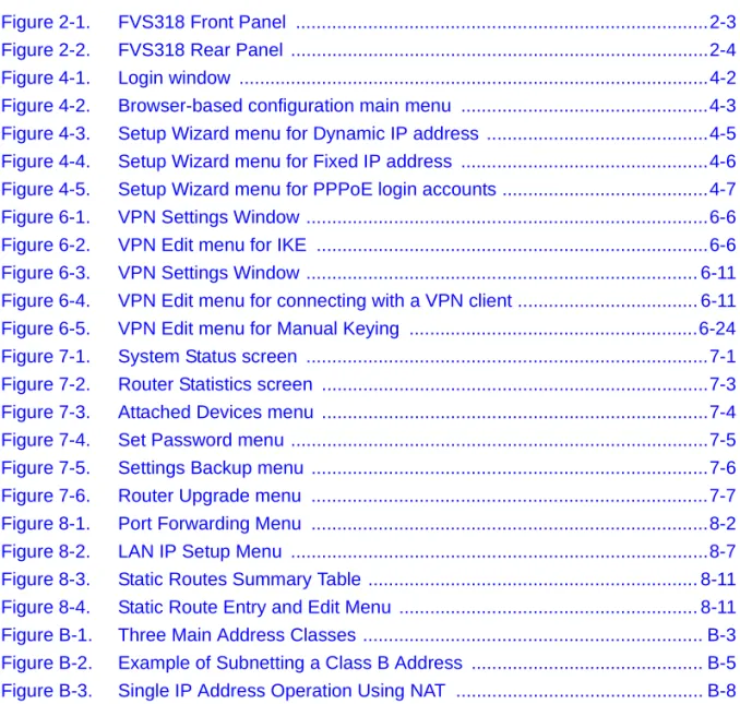
Figure 4-1. Login window ...4-2 Figure 4-2. Browser-based configuration main menu ...4-3 Figure 4-3. Setup Wizard menu for Dynamic IP address ...4-5 Figure 4-4. Setup Wizard menu for Fixed IP address ...4-6 Figure 4-5. Setup Wizard menu for PPPoE login accounts ...4-7 Figure 6-1. VPN Settings Window ...6-6 Figure 6-2. VPN Edit menu for IKE ...6-6 Figure 6-3. VPN Settings Window ... 6-11 Figure 6-4. VPN Edit menu for connecting with a VPN client ... 6-11 Figure 6-5. VPN Edit menu for Manual Keying ...6-24 Figure 7-1. System Status screen ...7-1 Figure 7-2. Router Statistics screen ...7-3 Figure 7-3. Attached Devices menu ...7-4 Figure 7-4. Set Password menu ...7-5 Figure 7-5. Settings Backup menu ...7-6 Figure 7-6. Router Upgrade menu ...7-7 Figure 8-1. Port Forwarding Menu ...8-2 Figure 8-2. LAN IP Setup Menu ...8-7 Figure 8-3. Static Routes Summary Table ... 8-11 Figure 8-4. Static Route Entry and Edit Menu ... 8-11 Figure B-1. Three Main Address Classes ... B-3 Figure B-2. Example of Subnetting a Class B Address ... B-5 Figure B-3. Single IP Address Operation Using NAT ... B-8
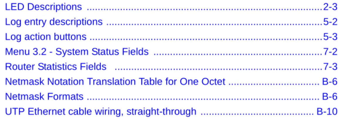
Table 5-2. Log action buttons ...5-3 Table 7-1. Menu 3.2 - System Status Fields ...7-2 Table 7-2. Router Statistics Fields ...7-3 Table B-1. Netmask Notation Translation Table for One Octet ... B-6 Table B-2. Netmask Formats ... B-6 Table B-3. UTP Ethernet cable wiring, straight-through ... B-10
Congratulations on your purchase of the NETGEAR™Model FVS318 Cable/DSL ProSafe VPN
Firewall. A firewall is a special type of router that incorporates features for security. The FVS318 VPN Firewall is a complete security solution that protects your network from attacks and
intrusions while allowing secure connections with other trusted users over the Internet. This guide describes the features of the firewall and provides installation and configuration instructions.
Typographical Conventions
This guide uses the following typographical conventions:
italics Book titles and UNIX file, command, and directory names. courier font Screen text, user-typed command-line entries.
Initial Caps Menu titles and window and button names.
[Enter] Named keys in text are shown enclosed in square brackets. The notation [Enter] is used for the Enter key and the Return key.
[Ctrl]+C Two or more keys that must be pressed simultaneously are shown in text linked with a plus (+) sign.
Special Message Formats
This guide uses the following formats to highlight special messages:
Technical Support
For help with any technical issues, contact Customer Support at 1-888-NETGEAR, or visit us on the Web at www.NETGEAR.com. The NETGEAR Web site includes an extensive knowledge base, answers to frequently asked questions, and a means for submitting technical questions online.
Related Publications
As you read this document, you may be directed to various RFC documents for further information. An RFC is a Request For Comment (RFC) published by the Internet Engineering Task Force (IETF), an open organization that defines the architecture and operation of the Internet. The RFC documents outline and define the standard protocols and procedures for the Internet. The documents are listed on the World Wide Web at www.ietf.org and are mirrored and indexed at many other sites worldwide.
Note:This format is used to highlight information of importance or special interest.
Caution:This format is used to highlight information that will help you prevent equipment failure or loss of data.
Warning:This format is used to highlight information about the possibility of injury or equipment damage.
Danger:This format is used to alert you that there is the potential for incurring an electrical shock if you mishandle the equipment.
For more information about address assignment, refer to the IETF documents RFC 1597, Address Allocation for Private Internets, and RFC 1466, Guidelines for Management of IP Address Space. For more information about IP address translation, refer to RFC 1631, The IP Network Address Translator (NAT).
Introduction
This chapter describes the features of the NETGEAR Model FVS318 Cable/DSL ProSafe VPN Firewall.
About the FVS318 VPN Firewall
The FVS318 VPN Firewall is a complete security solution that protects your network from attacks and intrusions while allowing secure connections with other trusted users over the Internet. Unlike simple Internet sharing routers that rely on NAT for security, the FVS318 uses Stateful Packet Inspection, widely considered as the most effective method of filtering IP traffic, to ensure secure firewall filtering. The FVS318 allows Internet access for up to 253 users, and is capable of eight simultaneous VPN connections.
Key Features
The FVS318 VPN Firewall offers the following features.
A Powerful, True Firewall
Unlike simple Internet sharing NAT routers, the FVS318 VPN Firewall is a true firewall, using stateful packet inspection to defend against hacker attacks. Its firewall features include: • Denial of Service (DoS) protection
Automatically detects and thwarts Denial of Service (DoS) attacks such as Ping of Death, SYN Flood, LAND Attack and IP Spoofing.
• Logs security incidents
The FVS318 VPN Firewall will log security events such as blocked incoming traffic, port scans, attacks, and administrator logins. You can configure the firewall to email the log to you at specified intervals. You can also configure the firewall to send immediate alert messages to your email address or email pager whenever a significant event occurs.
Virtual Private Networking (VPN)
The FVS318 VPN Firewall provides a secure encrypted connection between your local network and remote networks or clients. Its VPN features include
• Supports eight simultaneous VPN connections. • Supports industry standard VPN protocols
The FVS318 supports standard keying methods (Manual or IKE), standard authentication methods (MD5 and SHA-1), and standard encryption methods (DES, 3DES). It is compatible with many other VPN products.
• Supports up to 168 bit encryption (3DES) for maximum security.
Content Filtering
With its content filtering feature, the FVS318 VPN Firewall prevents objectionable content from reaching your PCs. The FVS318 allows you to control access to Internet content by screening for keywords within Web addresses. You can configure the FVS318 to log and report attempts to access objectional Internet sites.
Configurable Ethernet Connection
With its internal 8-port 10/100 switch, the FVS318 VPN Firewall can connect to either a 10 Mbps standard Ethernet network or a 100 Mbps Fast Ethernet network. The local LAN interface is autosensing and is capable of full-duplex or half-duplex operation.
The firewall incorporates Auto UplinkTMtechnology. Each LOCAL Ethernet port will
automatically sense whether the Ethernet cable plugged into the port should have a 'normal' connection (e.g. connecting to a PC) or an 'uplink' connection (e.g. connecting to a switch or hub). That port will then configure itself to the correct configuration. This feature also eliminates the need to worry about crossover cables, as Auto Uplink will accommodate either type of cable to make the right connection.
Protocol Support
The FVS318 VPN Firewall supports the Transmission Control Protocol/Internet Protocol (TCP/ IP) and Routing Information Protocol (RIP).
For further information about TCP/IP, refer toAppendix B, “Networks, Routing, and Firewall Basics.”
• IP Address Sharing by NAT
The FVS318 VPN Firewall allows several networked PCs to share an Internet account using only a single IP address, which may be statically or dynamically assigned by your Internet service provider (ISP). This technique, known as Network Address Translation (NAT), allows the use of an inexpensive single-user ISP account.
• Automatic Configuration of Attached PCs by DHCP
The FVS318 VPN Firewall dynamically assigns network configuration information, including IP, gateway, and domain name server (DNS) addresses, to attached PCs on the LAN using the Dynamic Host Configuration Protocol (DHCP). This feature greatly simplifies configuration of PCs on your local network.
• DNS Proxy
When DHCP is enabled and no DNS addresses are specified, the firewall provides its own address as a DNS server to the attached PCs. The firewall obtains actual DNS addresses from the ISP during connection setup and forwards DNS requests from the LAN.
• PPP over Ethernet (PPPoE)
PPP over Ethernet is a protocol for connecting remote hosts to the Internet over a DSL connection by simulating a dial-up connection. This feature eliminates the need to run a login program such as Entersys or WinPOET on your PC.
• Dynamic DNS
Dynamic DNS services allow remote users to find your network using a domain name when your IP address is not permanently assigned. The firewall contains a client that can connect to many popular Dynamic DNS services to register your dynamic IP address.
Easy Installation and Management
You can install, configure, and operate the FVS318 VPN Firewall within minutes after connecting it to the network. The following features simplify installation and management tasks:
• Browser-based management
Browser-based configuration allows you to easily configure your firewall from almost any type of personal computer, such as Windows, Macintosh, or Linux. A user-friendly Setup Wizard is provided and online help documentation is built into the browser-based Web Management Interface.
• Smart Wizard
The FVS318 automatically senses the type of Internet connection, asking you only for the information required for your type of ISP account.
• Remote management
The FVS318 allows you to login to the Web Management Interface from a remote location on the Internet. For security, you can limit remote management access to a specified remote IP address or range of addresses, and you can choose a nonstandard port number.
• Visual monitoring
The firewall’s front panel LEDs provide an easy way to monitor its status and activity.
Maintenance and Support
NETGEAR offers the following features to help you maximize your use of the firewall: • Flash EPROM for firmware upgrade
• Five-year warranty, two years on power adapter
Setting Up the Hardware
This chapter describes the Model FVS318 Cable/DSL ProSafe VPN Firewall hardware and provides instructions for installing it.
Package Contents
The product package should contain the following items: • Model FVS318 Cable/DSL ProSafe VPN Firewall • AC power adapter
• Category 5 (CAT5) Ethernet cable • Model FVS318 Resource CD, including:
— This manual
— Application Notes, Tools, and other helpful information • FVS318 Cable/DSL ProSafe VPN Firewall Installation Guide • Warranty and registration card
• Support information card
If any of the parts are incorrect, missing, or damaged, contact your NETGEAR dealer. Keep the carton, including the original packing materials, in case you need to return the product for repair.
Local Network Hardware Requirements
The FVS318 VPN Firewall is intended for use in a network of personal computers (PCs) that are interconnected by twisted-pair Ethernet cables.
PC Requirements
To install and run the FVS318 VPN Firewall over your network of PCs, each PC must have an installed Ethernet Network Interface Card (NIC) and an Ethernet cable. If the PC will connect to your network at 100 Mbps, you must use a Category 5 (CAT5) cable such as the cable provided with your firewall.
Access Device Requirement
The shared broadband access device (cable modem or DSL modem) must provide a standard 10 Mbps (10BASE-T) Ethernet interface.
The Firewall’s Front Panel
The front panel of the Model FVS318 Cable/DSL ProSafe VPN Firewall (Figure 2-1) contains status LEDs.
Figure 2-1. FVS318 Front Panel
You can use some of the LEDs to verify connections.Table 2-1lists and describes each LED on the front panel of the firewall. These LEDs are green when lit, except for the TEST LED, which is amber.
Table 2-1. LED Descriptions
Label Activity Description
POWER On Power is supplied to the firewall.
TEST On
Off
The system is initializing. The system is ready and running. INTERNET
LINK On The Internet port has detected a link with an attached device. ACT (Activity) Blinking Data is being transmitted or received by the Internet port. LOCAL
100 (100 Mbps) On Off
The Local port is operating at 100 Mbps. The Local port is operating at 10 Mbps. LINK/ACT
(Link/Activity)
On Blinking
The Local port has detected a link with an attached device. Data is being transmitted or received by the Local port.
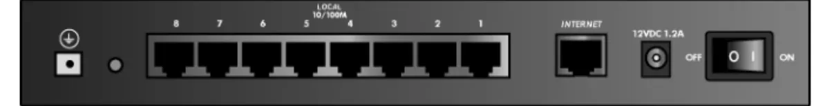
The Firewall’s Rear Panel
The rear panel of the FVS318 VPN Firewall (Figure 2-2) contains port connections.
Figure 2-2. FVS318 Rear Panel
The rear panel contains the following features: • Power switch
• AC power adapter outlet
• Internet (WAN) Ethernet port for connecting the firewall to a cable or DSL modem • Eight Local (LAN) Ethernet ports for connecting the firewall to the local PCs • Factory Default Reset pushbutton
• Grounding terminal
Connecting the Firewall
Before using your firewall, you need to do the following:
• Connect your cable or DSL modem to the Internet port of the firewall (described next. • Connect your local Ethernet network to the Local port(s) of the firewall (seepage 2-5). • Connect the power adapter (seepage 2-6)
Note:The Resource CD included with your firewall contains an animated Connection Guide to help you through this procedure.
Connecting to Your Internet Access Device
Your cable or DSL modem must provide a standard 10BASE-T Ethernet connection (not USB) for connection to your PC or network. The FVS318 VPN Firewall does not include a cable for this connection. Instead, use the Ethernet cable provided with your access device or any other standard 10BASE-T Ethernet cable. Follow these steps:
1. Locate the Ethernet cable currently going from your DSL or cable modem to the computer that you use to access the Internet.
Note:You must use the existing cable to connect the modem to your firewall, not to connect your PCs to your firewall. The Ethernet cable supplied by your ISP for connecting to your cable or DSL modem may be an Ethernet crossover cable rather than a normal
straight-through cable.
2. Remove this cable from the computer and insert that end into the Internet port on the firewall. 3. Turn the cable or DSL modem off for ten seconds, then on again.
Connecting to your Local Ethernet Network
Your local area network (LAN) will attach to the firewall’s Local ports shown inFigure 2-2. The Local ports are capable of operation at either 10 Mbps (10BASE-T) or 100 Mbps (100BASE-Tx), depending on the Ethernet interface of the attached PC, hub, or switch. For any connection which will operate at 100 Mbps, you must use a Category 5 (CAT5) rated Ethernet cable, such as the cable included with the firewall.
The FVS318 VPN Firewall incorporates an eight-port switch for connection to your local network. Connect up to eight PCs directly to any of the eight Local ports of the firewall using standard Ethernet cables such as the one included with your firewall.
If your local network consists of more than eight hosts, you will need to connect your firewall to another hub or switch. In this case, connect any LOCAL port of your firewall to any port of an Ethernet hub or switch. The firewall’s LOCAL port will automatically configure itself for the uplink connection.
Note:The FVS318 VPN Firewall incorporates Auto UplinkTMtechnology. Each LOCAL Ethernet
port will automatically sense whether the Ethernet cable plugged into the port should have a 'normal' connection (e.g. connecting to a PC) or an 'uplink' connection (e.g. connecting to a switch or hub). That port will then configure itself to the correct configuration. This feature also
eliminates the need to worry about crossover cables, as Auto Uplink will accommodate either type of cable to make the right connection.
Connecting the Power Adapter
To connect the firewall to the power adapter:
1. Plug the connector of the power adapter into the power adapter outlet on the rear panel of the firewall.
2. Plug the other end of the adapter into a standard wall outlet. 3. Turn the Power switch to the ON position.
4. Verify that the Power LED on the firewall is lit.
Verifying Connections
After applying power to the firewall, complete the following steps to verify the connections to it: 1. When power is first applied, verify that the POWER LED is on.
2. Verify that the TEST LED turns on within a few seconds. 3. After approximately 10 seconds, verify that:
a. The TEST LED has turned off.
b. The LOCAL LINK/ACT LEDs are lit for any local ports that are connected. c. The INTERNET LINK/ACT LED is lit.
If a LINK/ACT LED is lit, a link has been established to the connected device.
4. If any LOCAL port is connected to a 100 Mbps device, verify that the 100 LED for that port is lit.
The firewall is now properly attached to the network. Next, you need to prepare your network to access the Internet through the firewall. See the following chapter.
Preparing Your Network
This chapter describes how to prepare your PC network to connect to the Internet through the Model FVS318 Cable/DSL ProSafe VPN Firewall and how to order broadband Internet service from an Internet service provider (ISP). .
Preparing Your Personal Computers for IP Networking
Personal Computers access the Internet using a protocol called TCP/IP (Transmission Control Protocol/Internet Protocol). Each PC on your network must have TCP/IP installed and selected as its networking protocol. If a Network Interface Card (NIC) is already installed in your PC, then TCP/IP is probably already installed as well.
Note:In this chapter, we use the term “PC” to refer to personal computers in general, and not necessarily Windows computers.
Most PC operating systems include the software components you need for networking with TCP/ IP:
• Windows®95 or later includes the software components for establishing a TCP/IP network.
• Windows 3.1 does not include a TCP/IP component. You need to purchase a third-party TCP/ IP application package such as NetManage Chameleon.
Note:If an ISP technician configured your PC during the installation of a broadband modem, or if you configured it using instructions provided by your ISP, you may need to copy the current configuration information for use in the configuration of your firewall. Write down this information before reconfiguring your PCs. Refer to“Obtaining ISP Configuration Information (Windows)” onpage 3-10or“Obtaining ISP Configuration Information (Macintosh)” onpage 3-11for further information.
• Macintosh Operating System 7 or later includes the software components for establishing a TCP/IP network.
• All versions of UNIX or Linux include TCP/IP components. Follow the instructions provided with your operating system or networking software to install TCP/IP on your computer.. In your IP network, each PC and the firewall must be assigned a unique IP addresses. Each PC must also have certain other IP configuration information such as a subnet mask (netmask), a domain name server (DNS) address, and a default gateway address. In most cases, you should install TCP/IP so that the PC obtains its specific network configuration information automatically from a DHCP server during bootup. For a detailed explanation of the meaning and purpose of these configuration items, refer to “Appendix B, “Networks, Routing, and Firewall Basics.” The FVS318 VPN Firewall is shipped preconfigured as a DHCP server. The firewall assigns the following TCP/IP configuration information automatically when the PCs are rebooted:
• PC or workstation IP addresses—192.168.0.2 through 192.168.0.254 • Subnet mask—255.255.255.0
• Gateway address (the firewall)—192.168.0.1
These addresses are part of the IETF-designated private address range for use in private networks.
Configuring Windows 95, 98, and ME for IP Networking
As part of the PC preparation process, you need to manually install and configure TCP/IP on each networked PC. Before starting, locate your Windows CD; you may need to insert it during the TCP/IP installation process.
Install or Verify Windows Networking Components
To install or verify the necessary components for IP networking:
1. On the Windows taskbar, click the Start button, point to Settings, and then click Control Panel. 2. Double-click the Network icon.
You must have an Ethernet adapter, the TCP/IP protocol, and Client for Microsoft Networks.
If you need the adapter: a. Click the Add button.
b. Select Adapter, and then click Add.
c. Select the manufacturer and model of your Ethernet adapter, and then click OK. If you need TCP/IP:
a. Click the Add button.
b. Select Protocol, and then click Add. c. Select Microsoft.
Note:It is not necessary to remove any other network components shown in the Network window in order to install the adapter, TCP/IP, or Client for Microsoft Networks.
d. Select TCP/IP, and then click OK. If you need Client for Microsoft Networks: a. Click the Add button.
b. Select Client, and then click Add. c. Select Microsoft.
d. Select Client for Microsoft Networks, and then click OK. 3. Restart your PC for the changes to take effect.
Assign TCP/IP configuration by DHCP
After the TCP/IP protocol components are installed, each PC must be assigned specific information about itself and resources that are available on its network. The simplest way to configure this information is to allow the PC to obtain the information from the internal DHCP server of the FVS318 VPN Firewall. To use DHCP with the recommended default addresses, follow these steps:
1. Connect all PCs to the firewall, then restart the firewall and allow it to boot.
2. On each attached PC, open the Network control panel (refer to the previous section) and select the Configuration tab.
3. From the components list, select TCP/IP->(your Ethernet adapter) and click Properties. 4. In the IP Address tab, select “Obtain an IP address automatically”.
5. Select the Gateway tab.
6. If any gateways are shown, remove them. 7. Click OK.
8. Restart the PC.
Repeat steps 2 through 8 for each PC on your network.
Selecting Internet Access Method
1. On the Windows taskbar, click the Start button, point to Settings, and then click Control Panel. 2. Double-click the Internet Options icon.
3. Select “I want to set up my Internet connection manually” or “I want to connect through a Local Area Network” and click Next.
4. Select “I want to connect through a Local Area Network” and click Next. 5. Uncheck all boxes in the LAN Internet Configuration screen and click Next. 6. Proceed to the end of the Wizard.
Verifying TCP/IP Properties
After your PC is configured and has rebooted, you can check the TCP/IP configuration using the utility winipcfg.exe:
1. On the Windows taskbar, click the Start button, and then click Run. 2. Typewinipcfg, and then click OK.
The IP Configuration window opens, which lists (among other things), your IP address, subnet mask, and default gateway.
3. From the drop-down box, select your Ethernet adapter.
The window is updated to show your settings, which should match the values below if you are using the default TCP/IP settings that NETGEAR recommends:
• The IP address is between 192.168.0.2 and 192.168.0.254 • The subnet mask is 255.255.255.0
• The default gateway is 192.168.0.1
Configuring Windows NT or 2000 for IP Networking
As part of the PC preparation process, you need to manually install and configure TCP/IP on each networked PC. Before starting, locate your Windows CD; you may need to insert it during the TCP/IP installation process.
Install or Verify Windows Networking Components
To install or verify the necessary components for IP networking:
3. If an Ethernet adapter is present in your PC, you should see an entry for Local Area Connection. Double-click that entry.
4. Select Properties.
5. Verify that ‘Client for Microsoft Networks’ and ‘Internet Protocol (TCP/IP)’ are present. If not, select Install and add them.
6. Select ‘Internet Protocol (TCP/IP)’, click Properties, and verify that “Obtain an IP address automatically is selected.
7. Click OK and close all Network and Dialup Connections windows. 8. Make sure your PC is connected to the firewall, then reboot your PC.
Verifying TCP/IP Properties
To check your PC’s TCP/IP configuration:
1. On the Windows taskbar, click the Start button, and then click Run. The Run window opens.
2. Typecmdand then click OK. A command window opens 3. Typeipconfig /all
Your IP Configuration information will be listed, and should match the values below if you are using the default TCP/IP settings that NETGEAR recommends:
• The IP address is between 192.168.0.2 and 192.168.0.254 • The subnet mask is 255.255.255.0
• The default gateway is 192.168.0.1 4. Typeexit
Configuring the Macintosh for IP Networking
Beginning with Macintosh Operating System 7, TCP/IP is already installed on the Macintosh. On each networked Macintosh, you will need to configure TCP/IP to use DHCP.
MacOS 8.6 or 9.x
1. From the Apple menu, select Control Panels, then TCP/IP. The TCP/IP Control Panel opens:
2. From the “Connect via” box, select your Macintosh’s Ethernet interface. 3. From the “Configure” box, select Using DHCP Server.
You can leave the DHCP Client ID box empty. 4. Close the TCP/IP Control Panel.
5. Repeat this for each Macintosh on your network. MacOS X
1. From the Apple menu, choose System Preferences, then Network. 2. If not already selected, select Built-in Ethernet in the Configure list. 3. If not already selected, Selct Using DHCP in the TCP/IP tab. 4. Click Save.
Verifying TCP/IP Properties (Macintosh)
After your Macintosh is configured and has rebooted, you can check the TCP/IP configuration by returning to the TCP/IP Control Panel. From the Apple menu, select Control Panels, then TCP/IP.
The panel is updated to show your settings, which should match the values below if you are using the default TCP/IP settings that NETGEAR recommends:
• The IP Address is between 192.168.0.2 and 192.168.0.254 • The Subnet mask is 255.255.255.0
• The Router address is 192.168.0.1
If you do not see these values, you may need to restart your Macintosh or you may need to switch the “Configure” setting to a different option, then back again to “Using DHCP Server”.
Your Internet Account
For access to the Internet, you need to contract with an Internet service provider (ISP) for a single-user Internet access account using an external broadband access device such as a cable modem or DSL modem. This modem must be a separate physical box (not a card) and must provide an Ethernet port intended for connection to a Network Interface Card (NIC) in a PC. Your firewall does not support a USB-connected broadband modem.
For a single-user Internet account, your ISP supplies TCP/IP configuration information for one PC. With a typical account, much of the configuration information is dynamically assigned when your PC is first booted up while connected to the ISP, and you will not need to know that dynamic information.
In order to share the Internet connection among several computers, your firewall takes the place of the single PC, and you need to configure it with the TCP/IP information that the single PC would normally use. When the firewall’s Internet port is connected to the broadband modem, the firewall appears to be a single PC to the ISP. The firewall then allows the PCs on the local network to masquerade as the single PC to access the Internet through the broadband modem. The method used by the firewall to accomplish this is called Network Address Translation (NAT) or IP masquerading.
Login Protocols
Some ISPs require a special login protocol, in which you must enter a login name and password in order to access the Internet. If you normally log in to your Internet account by running a program such as WinPOET or EnterNet, then your account uses PPP over Ethernet (PPPoE).
When you configure your firewall, you will need to enter your login name and password in the firewall’s configuration menus. After your network and firewall are configured, the firewall will perform the login task when needed, and you will no longer need to run the login program from your PC. It is not necessary to uninstall the login program.
Account Information
Unless these items are dynamically assigned by the ISP, your ISP should give you the following basic information for your account:
• An IP address and subnet mask
• A gateway IP address, which is the address of the ISP’s router • One or more domain name server (DNS) IP addresses
• Host name and domain suffix
For example, your account’s full server names may look like this: mail.xxx.yyy.com
If any of these items are dynamically supplied by the ISP, your firewall automatically acquires them. If an ISP technician configured your PC during the installation of the broadband modem, or if you configured it using instructions provided by your ISP, you need to copy configuration information from your PC’s Network TCP/IP Properties window (or Macintosh TCP/IP Control Panel) before reconfiguring your PC for use with the firewall. These procedures are described next.
Obtaining ISP Configuration Information (Windows)
As mentioned above, you may need to collect configuration information from your PC so that you can use this information when you configure the FVS318 VPN Firewall. Following this procedure is only necessary when your ISP does not dynamically supply the account information.
To get the information you need to configure the firewall for Internet access:
1. On the Windows taskbar, click the Start button, point to Settings, and then click Control Panel. 2. Double-click the Network icon.
The Network window opens, which displays a list of installed components. 3. Select TCP/IP, and then click Properties.
The TCP/IP Properties dialog box opens. 4. Select the IP Address tab.
If an IP address and subnet mask are shown, write down the information. If an address is present, your account uses a fixed (static) IP address. If no address is present, your account uses a dynamically-assigned IP address. Click “Obtain an IP address automatically”. 5. Select the Gateway tab.
If an IP address appears under Installed Gateways, write down the address. This is the ISP’s gateway address. Select the address and then click Remove to remove the gateway address. 6. Select the DNS Configuration tab.
If any DNS server addresses are shown, write down the addresses. If any information appears in the Host or Domain information box, write it down. Click Disable DNS.
7. Click OK to save your changes and close the TCP/IP Properties dialog box. You are returned to the Network window.
8. Click OK.
Obtaining ISP Configuration Information (Macintosh)
As mentioned above, you may need to collect configuration information from your Macintosh so that you can use this information when you configure the FVS318 VPN Firewall. Following this procedure is only necessary when your ISP does not dynamically supply the account information. To get the information you need to configure the firewall for Internet access:
1. From the Apple menu, select Control Panels, then TCP/IP.
The TCP/IP Control Panel opens, which displays a list of configuration settings. If the “Configure” setting is “Using DHCP Server”, your account uses a dynamically-assigned IP address. In this case, close the Control Panel and skip the rest of this section.
2. If an IP address and subnet mask are shown, write down the information.
3. If an IP address appears under Router address, write down the address. This is the ISP’s gateway address.
4. If any Name Server addresses are shown, write down the addresses. These are your ISP’s DNS addresses.
5. If any information appears in the Search domains information box, write it down. 6. Change the “Configure” setting to “Using DHCP Server”.
7. Close the TCP/IP Control Panel.
Restarting the Network
Once you’ve set up your computers to work with the firewall, you must reset the network for the devices to be able to communicate correctly.
1. Turn off the DSL or cable modem, wait 15 seconds, and then turn it on again 2. Turn off the firewall, and then turn it on again and wait until the Test light turns off. 3. Restart any computer that is connected to the firewall.
Note:If the modem doesn’t have an on/off switch, either pull the modem’s power adapter out of the wall socket or power down the power strip.
Ready for Configuration
After configuring all of your PCs for TCP/IP networking and connecting them to the local network of your FVS318 VPN Firewall, you are ready to access and configure the firewall. Proceed to the next chapter.
Basic Configuration
This chapter describes how to perform the basic configuration of your Model FVS318 Cable/DSL ProSafe VPN Firewall using the Setup Wizard, which walks you through the configuration process for your Internet connection.
Accessing the Web Configuration Manager
In order to use the browser-based Web Configuration Manager, your PC must have a web browser program installed such as Microsoft Internet Explorer or Netscape Navigator. Because the
Configuration Manager uses Java, your Web browser must be Java-enabled and support HTTP uploads. NETGEAR recommends using Microsoft Internet Explorer or Netscape Navigator 4.0 or above. Free browser programs are readily available for Windows, Macintosh, or UNIX/Linux. To configure for Internet access using your browser:
1. Connect your PC and firewall as described in the previous chapter. Make sure your PC has been rebooted since connecting with the firewall. 2. Launch your web browser.
Note:If you normally use a login program (such as Enternet or WinPOET) to access the Internet, do not launch that program.
3. Click your browser’s Stop button.
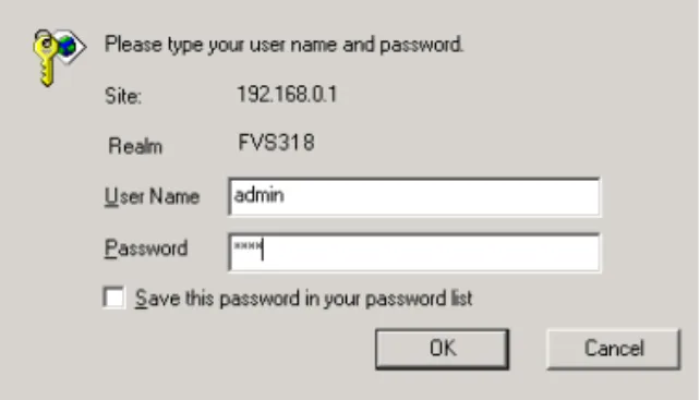
A login window opens as shown inFigure 4-1below:.
Figure 4-1. Login window
This screen may have a different appearance in other browsers.
5. Typeadminin the User Name box,password in the Password box, and then click OK. (If your firewall password was previously changed, enter the current password.) If your firewall has not yet been configured, the Setup Wizard should launch automatically. Otherwise, the main menu of the Web Configuration Manager will appear as shown inFigure 4-2 below:
Figure 4-2. Browser-based configuration main menu
You can manually configure your firewall using this menu as described in“Manual
Configuration“ on page 4-8, or you can allow the Setup Wizard to determine your configuration as described in the following chapter.
Configuration using the Setup Wizard
The Web Configuration Manager contains a Setup Wizard that can automatically determine your network connection type. If the Setup Wizard does not launch automatically, click on the Setup Wizard heading in the upper left of the opening screen, shown inFigure 4-2.
When the Wizard launches, allow the firewall to automatically determine your connection type by selecting Yes in the menu below and clicking Next:
The Setup Wizard will now check for a connection on the Internet port. If the Setup Wizard determines that there is no connection to the Internet port, you will be prompted to check the physical connection between your firewall and cable or DSL modem. When the connection is properly made, the firewall’s Internet LED should be on.
Next, the Setup Wizard will attempt to determine which of the following connection types your Internet service account uses:
• Dynamic IP assignment • Fixed IP address assignment • A login protocol such as PPPoE
The Setup Wizard will report which connection type it has discovered, and it will then use the appropriate configuration menu for that connection type.
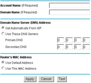
Configuring for Dynamic IP Account
If the Setup Wizard determines that your Internet service account uses Dynamic IP assignment, you will be directed to the menu shown inFigure 4-3below:
Figure 4-3. Setup Wizard menu for Dynamic IP address
1. Enter your Account Name (may also be called Host Name) and Domain Name. These
parameters may be necessary to access your ISP’s services such as mail or news servers. If you leave the Domain Name field blank, the firewall will attempt to learn the domain
automatically from the ISP. If this is not successful, you may need to enter it manually. 2. Domain Name Server (DNS) Address: If you know that your ISP does not automatically
transmit DNS addresses to the firewall during login, select “Use these DNS servers” and enter the IP address of your ISP’s Primary DNS Server. If a Secondary DNS Server address is available, enter it also.
A DNS server is a host on the Internet that translates Internet names (such as www addresses) to numeric IP addresses. Typically your ISP transfers the IP addresses of one or two DNS servers to your firewall during login. If the ISP does not transfer an address, you must obtain it from the ISP and enter it manually here. If you enter an address here, you should reboot your PCs after configuring the firewall.
3. Router’s MAC Address: This section determines the Ethernet MAC address that will be used by the firewall on the Internet port. If your ISP allows access by only one specific PC’s Ethernet MAC address, select "Use this MAC address". The firewall will then capture and use the MAC address of the PC that you are now using. You must be using the one PC that is allowed by the ISP.
Some ISPs will register the Ethernet MAC address of the network interface card in your PC when your account is first opened. They will then only accept traffic from the MAC address of that PC. This feature allows your firewall to masquerade as that PC by using its MAC address.
4. Click on Apply, then proceed to“Completing the Configuration“ on page 4-9.
Configuring for Fixed IP Account
If the Setup Wizard determines that your Internet service account uses Fixed IP assignment, you will be directed to the menu shown inFigure 4-4below:
Figure 4-4. Setup Wizard menu for Fixed IP address
1. Enter your assigned IP Address, Subnet Mask, and the IP Address of your ISP’s gateway router. This information should have been provided to you by your ISP.
2. Domain Name Server (DNS) Address: If you know that your ISP does not automatically transmit DNS addresses to the firewall during login, select “Use these DNS servers” and enter the IP address of your ISP’s Primary DNS Server. If a Secondary DNS Server address is available, enter it also.
A DNS server is a host on the Internet that translates Internet names (such as www addresses) to numeric IP addresses. Typically your ISP transfers the IP addresses of one or two DNS servers to your firewall during login. If the ISP does not transfer an address, you must obtain it from the ISP and enter it manually here. If you enter an address here, you should reboot your PCs after configuring the firewall.
3. Click on Apply, then proceed to“Completing the Configuration“ on page 4-9.
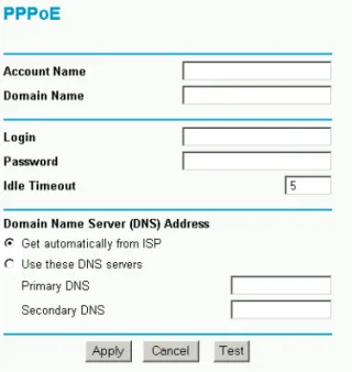
Configuring for an Account with Login
If the Setup Wizard determines that your Internet service account uses a login protocol such as PPP over Ethernet (PPPoE), you will be directed to a menu like the PPPoE menu shown in Figure 4-5below:
Figure 4-5. Setup Wizard menu for PPPoE login accounts
1. Enter your Account Name (may also be called Host Name) and Domain Name. These
parameters may be necessary to access your ISP’s services such as mail or news servers. If you leave the Domain Name field blank, the firewall will attempt to learn the domain
automatically from the ISP. If this is not successful, you may need to enter it manually. 2. Enter the PPPoE login user name and password provided by your ISP. These fields are case
Note:You will no longer need to launch the ISP’s login program on your PC in order to access the Internet. When you start an Internet application, your firewall will automatically log you in.
3. Domain Name Server (DNS) Address: If you know that your ISP does not automatically transmit DNS addresses to the firewall during login, select “Use these DNS servers” and enter the IP address of your ISP’s Primary DNS Server. If a Secondary DNS Server address is available, enter it also.
A DNS server is a host on the Internet that translates Internet names (such as www addresses) to numeric IP addresses. Typically your ISP transfers the IP addresses of one or two DNS servers to your firewall during login. If the ISP does not transfer an address, you must obtain it from the ISP and enter it manually here. If you enter an address here, you should reboot your PCs after configuring the firewall.
4. Click on Apply, then proceed to“Completing the Configuration“ on page 4-9.
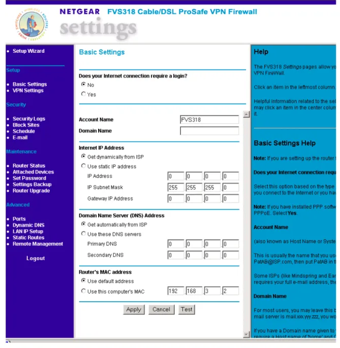
Manual Configuration
You can manually configure the firewall in the Basic Settings menu shown inFigure 4-2using these steps:
1. Select whether your Internet connection requires a login.
Select ‘Yes’ if you normally must launch a login program such as Enternet or WinPOET in order to access the Internet.
2. Enter your Account Name (may also be called Host Name) and Domain Name. These parameters may be necessary to access your ISP’s services such as mail or news servers. 3. (If displayed) Enter the PPPoE login user name and password provided by your ISP. These
fields are case sensitive. If you wish to change the login timeout, enter a new value in minutes. Note:You will no longer need to launch the ISP’s login program on your PC in order to access the Internet. When you start an Internet application, your firewall will automatically log you in.
4. Internet IP Address: If your ISP has assigned you a permanent, fixed (static) IP address for your PC, select “Use static IP address”. Enter the IP address that your ISP assigned. Also enter the netmask and the Gateway IP address. The Gateway is the ISP’s router to which your firewall will connect.
5. Domain Name Server (DNS) Address: If you know that your ISP does not automatically transmit DNS addresses to the firewall during login, select “Use these DNS servers” and enter the IP address of your ISP’s Primary DNS Server. If a Secondary DNS Server address is available, enter it also.
A DNS server is a host on the Internet that translates Internet names (such as www addresses) to numeric IP addresses. Typically your ISP transfers the IP addresses of one or two DNS servers to your firewall during login. If the ISP does not transfer an address, you must obtain it from the ISP and enter it manually here. If you enter an address here, you should reboot your PCs after configuring the firewall.
6. Router’s MAC Address: This section determines the Ethernet MAC address that will be used by the firewall on the Internet port. Some ISPs will register the Ethernet MAC address of the network interface card in your PC when your account is first opened. They will then only accept traffic from the MAC address of that PC. This feature allows your firewall to masquerade as that PC by “cloning” its MAC address.
To change the MAC address, select "Use this Computer’s MAC address". The firewall will then capture and use the MAC address of the PC that you are now using. You must be using the one PC that is allowed by the ISP.
7. Click Apply, then proceed toCompleting the Configuration.
Completing the Configuration
Click on the Test button to test your Internet connection. If the NETGEAR website does not appear within one minute, refer toChapter 9, “Troubleshooting”.
Your firewall is now configured to provide Internet access for your network. When your firewall and PCs are configured correctly, your firewall automatically accesses the Internet when one of your LAN devices requires access. It is not necessary to run a dialer or login application such as Dial-Up Networking or Enternet to connect, log in, or disconnect. These functions are performed by the firewall as needed.
To access the Internet from any PC connected to your firewall, launch a browser such as Microsoft Internet Explorer or Netscape Navigator. You should see the firewall’s Internet LED blink, indicating communication to the ISP. The browser should begin to display a Web page.
The following chapters describe how to configure the Advanced features of your firewall, and how to troubleshoot problems that may occur.
Configuring Security Features
This chapter describes how to use the security features of your Model FVS318 Cable/DSL ProSafe VPN Firewall. The firewall provides you with Web content filtering by keyword, and with security incident logging. You can configure the firewall to e-mail its log to you at specified intervals. You can also configure the firewall to send immediate alert messages to your e-mail address or e-mail pager whenever a significant security event occurs.
To configure these features of your firewall, click on the subheadings under the Security heading in the Main Menu of the browser interface.
Security Log
The firewall will log security-related events such as denied incoming service requests, hacker probes, and administrator logins. If you enabled content filtering in the Block Sites menu, the Logs page shows you when someone on your network tried to access a blocked site. If you enabled e-mail notification, you'll receive these logs in an e-mail message. If you don't have e-mail notification enabled, you can view the logs here. An example is shown below:
Log entries are described inTable 5-1
Table 5-1. Log entry descriptions
Field Description
Date and Time The date and time the log entry was recorded. Description or
Action
The type of event and what action was taken if any. Source IP The IP address of the initiating device for this log entry. Source port and
interface
The service port number of the initiating device, and whether it originated from the LAN or WAN
Destination The name or IP address of the destination device or website. Destination port
and interface
The service port number of the destination device, and whether it’s on the LAN or WAN.
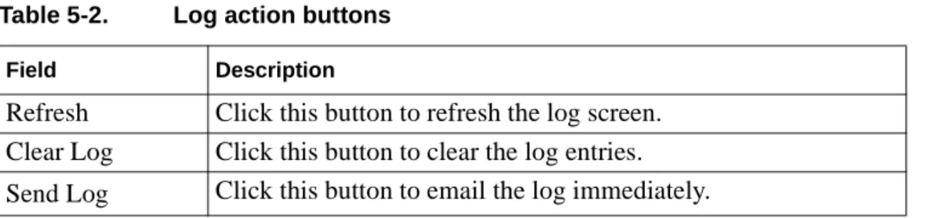
Log action buttons are described inTable 5-2
Block Sites
The FVS318 VPN Firewall allows you to restrict access based on Web addresses and Web address keywords. Up to 255 entries are supported in the Keyword list. The Keyword Blocking menu is shown below:
To enable keyword blocking, check “Turn keyword blocking on”, then click Apply. Be sure that a time period for blocking is specified on the Schedule menu.
To add a keyword or domain, type it in the Keyword box, click Add Keyword, then click Apply. To delete a keyword or domain, select it from the list, click Delete Keyword, then click Apply. Table 5-2. Log action buttons
Field Description
Refresh Click this button to refresh the log screen. Clear Log Click this button to clear the log entries. Send Log Click this button to email the log immediately.
Keyword application examples:
• If the keyword "XXX" is specified, the URL <http://www.badstuff.com/xxx.html> is blocked. • If the keyword “.com” is specified, only websites with other domain suffixes (such as .edu or
.gov) can be viewed.
• If you wish to block all Internet browsing access during a scheduled period, enter the keyword “.” and set the schedule in the Schedule menu.
To specify a Trusted User, enter that PC’s IP address in the Trusted User box and click Apply. You may specify one Trusted User, which is a PC that will be exempt from blocking and logging. Since the Trusted User will be identified by an IP address, you should configure that PC with a fixed IP address.
Schedule
If you enabled content filtering in the Block Sites menu, you can set up a schedule for when blocking occurs or when access isn't restricted. The firewall allows you to specify when blocking will be enforced by configuring the Schedule tab shown below:
To block keywords or Internet domains based on a schedule: 1. Select Every Day or select one or more days.
2. If you want to limit access completely for the selected days, select All Day.
Otherwise, If you want to limit access during certain times for the selected days, type a Start Blocking time and an End Blocking time.
Note:Note: Enter the values as 24-hour time. For example, 10:30 am would be 10 hours and 30 minutes and 10:30 pm would be 22 hours and 30 minutes.
Time Zone
The FVS318 VPN Firewall uses the Network Time Protocol (NTP) to obtain the current time and date from one of several Network Time Servers on the Internet. In order to localize the time for your log entries, you must select your Time Zone from the list.
If your region uses Daylight Savings Time, you must manually check Adjust for Daylight Savings Time at the beginning of the Daylight Savings Time, and uncheck it at the end. Enabling Daylight Savings Time will cause one hour to be added to the standard time.
The firewall has a list of publicly available NTP servers. If you would prefer to use a particular NTP server as the primary server, enter its IP address under Use this NTP Server.
In order to receive logs and alerts by e-mail, you must provide your e-mail information in the E-Mail subheading:
• Turn e-mail notification on
Check this box if you wish to receive e-mail logs and alerts from the firewall. • Your outgoing mail server
Enter the name or IP address of your ISP’s outgoing (SMTP) mail server (such as
mail.myISP.com). You may be able to find this information in the configuration menu of your e-mail program. If you leave this box blank, log and alert messages will not be sent via e-mail. • Send to this e-mail address
Enter the e-mail address to which logs and alerts are sent. This e-mail address will also be used as the From address. If you leave this box blank, log and alert messages will not be sent via e-mail.
You can specify that logs are automatically sent to the specified e-mail address with these options: • Send alert immediately
Check this box if you would like immediate notification of a significant security event, such as a known attack, port scan, or attempted access to a blocked site.
• Send logs according to this schedule
Specifies how often to send the logs: Hourly, Daily, Weekly, or When Full. – Day for sending log
Specifies which day of the week to send the log. Relevant when the log is sent weekly or daily.
– Time for sending log
Specifies the time of day to send the log. Relevant when the log is sent daily or weekly. If the Weekly, Daily or Hourly option is selected and the log fills up before the specified period, the log is automatically e-mailed to the specified e-mail address. After the log is sent, the log is cleared from the firewall’s memory. If the firewall cannot e-mail the log file, the log buffer may fill up. In this case, the firewall overwrites the log and discards its contents. The FVS318 VPN Firewall uses the Network Time Protocol (NTP) to obtain the current time and date from one of several Network Time Servers on the Internet. In order to localize the time for your log entries, you must specify your Time Zone:
• Time Zone
Select your local time zone. This setting will be used for the blocking schedule and for time-stamping log entries.
• Daylight Savings Time
Virtual Private Networking
This chapter describes how to use the the virtual private networking (VPN) features of the FVS318 VPN Firewall. A VPN provides secure, encrypted communication between your local network and a remote network or computer.
Note:The FVS318 VPN Firewall uses industry standard VPN protocols. However, due to variations in how manufacturers interpret these standards, many VPN products are not interoperable. NETGEAR provides support for connections between two FVS318 VPN Firewalls, and between an FVS318 VPN Firewall and the SafeNet Secure VPN Client for Windows. Although the FVS318 can interoperate with many other VPN products, it is not possible for NETGEAR to provide specific technical support for every other interconnection.
What is a VPN
A VPN can be thought of as a secure tunnel passing through the Internet, connecting two devices such as a PC or router, which form the two tunnel endpoints. At one endpoint, data is encapsulated and encrypted, then transmitted through the Internet. At the far endpoint, the data is received, unencapsulated and decrypted. Although the data may pass through several Internet routers between the endpoints, the encapsulation and encryption forms a virtual “tunnel” for the data.
The tunnel endpoint device, which encodes or decodes the data, can either be a PC running VPN client software or a VPN-enabled router or server. Several software standards exist for VPN data encapsulation and encryption, such as PPTP and IPSec. Your FVS318 VPN Firewall uses IPSec. To set up a VPN connection, you must configure each endpoint with specific identification and connection information describing the other endpoint. This set of configuration information defines a security association (SA) between the two points. The FVS318 is capable of eight Security Associations.
Two common applications of VPN are
• secure access from a remote PC, such as a telecommuter connecting to an office network • secure access between two networks, such as a branch office and a main office
These applications are described below. DATA PACKET
ENCRYPTION AND ENCAPSULATION
UNENCAPSULATION AND DECRYPTION INTERNET
TRANSMISSION VIA INTERNET
Accessing Network Resources from a VPN Client PC
VPN client remote access allows a remote PC to connect to your network from any location on the Internet. In this case, the remote PC is one tunnel endpoint, running VPN client software. The NETGEAR VPN-enabled router on your network is the other tunnel endpoint, as shown below.
In some cases, the client PC may connect to the Internet through a local non-VPN-enabled router, as shown below:
If the non-VPN router is performing NAT, it must support “VPN-passthrough” of IPSec-encoded data.
For a PC to act as a tunnel endpoint to your FVS318 VPN Firewall, the PC must run a VPN client program based on the IPSec protocol. NETGEAR recommends that you use the SafeNet
SoftRemote (or Soft-PK) VPN client program, which is available from SafeNet
(www.safenet-inc.com). Installation and configuration instructions for the SafeNet client program are provided onpage 6-13.
INTERNET
A T LA N T A B A YS A NC L AT AR A
CLIENT
VPN ROUTER
LAN
INTERNET
A T LA N T A B A YS A NT AC L AR A
CLIENT
SIMPLE ROUTER
VPN ROUTER
Linking Two Networks Together
A VPN between two NETGEAR VPN-enabled routers is a good way to connect branch offices and business partners over the Internet, offering an affordable, high-performance alternative to leased site-to-site lines. The VPN also provides access to remote network resources when NAT is enabled and remote computers have been assigned private IP addresses.
Planning the VPN
When planning your VPN, you must make a few choices first: • Will the remote end be a network or a single PC?
If Network: The two endpoint networks must have different LAN IP address ranges. For example, if both ends are using the NETGEAR default address range of 192.168.0.x, the connection will not work. Change one router’s LAN IP Address and DHCP range to a different range such as 192.168.1.x.
If Single PC: If the remote endpoint is a single PC running a VPN client, its destination address must be a single IP address, with a subnet mask of 255.255.255.255.
• Does one side have a dynamic IP address? At least one side must have a fixed IP address.
The side with a dynamic IP address must always be the initiator of the connection.
• Will you be using the simpler Internet Key Exchange (IKE) setup, or Manual Keying, in which you must specify each phase of the connection?
• What level of encryption will you use (56 bit DES or 168 bit 3DES)?
Configuring a VPN Between Two LANs
This procedure describes linking two LANs using an FVS318 at each end.
INTERNET
VPN ROUTER
VPN ROUTER
LAN LAN
Check the LAN Address Ranges
First, be sure that the two LANs have different IP address ranges. If both networks are using the NETGEAR default address range of 192.168.0.x, the connection will not work. In this case, you must change one FVS318’s LAN IP Address and DHCP range to a different range such as 192.168.3.x.. To change the second FVS318’s LAN address range, follow these steps: 1. Go to the LAN IP Setup menu of the second FVS318
2. Change the IP Address to 192.168.3.1
3. Change the DHCP Starting Address to 192.168.3.2 4. Change the DHCP Ending Address to 192.168.3.100
5. Change any Reserved IP Addresses to be part of the 192.168.3.x network
6. If you have configured Port Forwarding, Trusted User, or Static Routes, you may need to change these configurations as well.
7. Click Apply
At this point the firewall’s IP address will change and you will be disconnected from the firewall’s configuration.
8. Reboot all PCs on this network. Configure the First Firewall
The simplest method of linking the two firewalls will be to use the IKE protocol, allowing them to automatically negotiate the connection and exchange keying information. In this case, the
configuration of the two firewalls differs only in the setting of the destination address ranges. To configure the first firewall, follow these steps:
1. From the Main Menu of the browser interface click the link labeled VPN Settings. The VPN Settings window opens as shown inFigure 6-1below:
Figure 6-1. VPN Settings Window
2. Click the button next to an unused profile in the table and click Edit. The VPN Settings - IKE window opens as shown inFigure 6-2below: