ETSI EN 301 406
V2.2.1
(2016-04)
Digital Enhanced Cordless Telecommunications (DECT);
Harmonised Standard covering the essential requirements
of article 3.2 of the Directive 2014/53/EU
Reference
REN/DECT-000300
Keywords
DECT, digital, generic, radio, regulation, testing
ETSI
650 Route des Lucioles
F-06921 Sophia Antipolis Cedex - FRANCE Tel.: +33 4 92 94 42 00 Fax: +33 4 93 65 47 16
Siret N° 348 623 562 00017 - NAF 742 C Association à but non lucratif enregistrée à la
Sous-Préfecture de Grasse (06) N° 7803/88
Important notice
The present document can be downloaded from:
http://www.etsi.org/standards-search
The present document may be made available in electronic versions and/or in print. The content of any electronic and/or print versions of the present document shall not be modified without the prior written authorization of ETSI. In case of any
existing or perceived difference in contents between such versions and/or in print, the only prevailing document is the print of the Portable Document Format (PDF) version kept on a specific network drive within ETSI Secretariat. Users of the present document should be aware that the document may be subject to revision or change of status.
Information on the current status of this and other ETSI documents is available at
https://portal.etsi.org/TB/ETSIDeliverableStatus.aspx
If you find errors in the present document, please send your comment to one of the following services:
https://portal.etsi.org/People/CommiteeSupportStaff.aspx
Copyright Notification
No part may be reproduced or utilized in any form or by any means, electronic or mechanical, including photocopying and microfilm except as authorized by written permission of ETSI.
The content of the PDF version shall not be modified without the written authorization of ETSI. The copyright and the foregoing restriction extend to reproduction in all media.
© European Telecommunications Standards Institute 2016. All rights reserved.
Contents
Intellectual Property Rights ... 10
Foreword ... 10
Modal verbs terminology ... 10
1 Scope
... 11
2 References
... 11
2.1 Normative references ... 11
2.2 Informative references ... 12
3 Definitions,
symbols and abbreviations ... 13
3.1 Definitions ... 13
3.2 Symbols ... 15
3.3 Abbreviations ... 15
4 Technical
requirements specifications ... 16
4.1 Environmental profile ... 16 4.2 Overview ... 16 4.2.0 General ... 16 4.2.1 Test suites ... 16 4.2.2 Test groups... 17 4.2.3 Test cases ... 17 4.3 Applicant's declaration ... 17 4.4 Applicability of tests ... 18 4.4.0 Introduction... 18
4.4.1 Equipment that includes only a DECT RF receiver ... 18
4.4.2 Equipment that includes a radio transmitter ... 18
4.4.3 CTAs ... 18
4.4.4 Equipment with combined FT and PT functionality ... 18
4.4.4.0 General ... 18
4.4.4.1 Wireless Relay Station ... 18
4.4.4.2 Direct PP to PP communication ... 18
4.4.4.3 Distributed Communications... 19
4.4.5 Provision of 4 Mbit/s services. Equipment that is capable of using higher level modulation ... 19
4.4.6 Equipment supporting additional carriers ... 19
4.5 Conformance requirements ... 19
4.5.1 Accuracy and stability of RF carriers ... 19
4.5.1.1 Definition ... 19
4.5.1.2 Limits ... 19
4.5.1.3 Conformance ... 20
4.5.2 Accuracy and stability of timing parameters ... 20
4.5.2.0 General ... 20
4.5.2.1 Definitions ... 20
4.5.2.1.1 Slot structure ... 20
4.5.2.1.2 Definition of the position of p0 ... 20
4.5.2.2 Limits ... 20 4.5.2.3 Conformance ... 20 4.5.3 Transmission burst ... 20 4.5.3.1 Definitions ... 20 4.5.3.1.1 Physical packets... 20 4.5.3.1.2 Transmitted power ... 20
4.5.3.1.3 Normal Transmitted Power (NTP) ... 20
4.5.3.1.4 Transmitter attack time ... 20
4.5.3.1.5 Transmitter release time ... 21
4.5.3.1.6 Minimum power ... 21
4.5.3.1.7 Maximum power ... 21
4.5.3.1.8 Maintenance of transmission after packet end ... 21
4.5.3.1.9 Transmitter idle power output ... 21
4.5.3.3 Conformance ... 21
4.5.4 Transmitted power ... 21
4.5.4.1 Definitions ... 21
4.5.4.1.0 Transceiver and PNTP definitions ... 21
4.5.4.1.1 PP and RFP with an integral antenna ... 22
4.5.4.1.2 PP and RFP with external connections for all antennas ... 22
4.5.4.1.3 PP and RFP with both integral and external antennas ... 22
4.5.4.2 Limits ... 22 4.5.4.3 Conformance ... 22 4.5.4.4 Multi-transceiver systems ... 22 4.5.5 RF carrier modulation ... 22 4.5.5.1 Definition ... 22 4.5.5.2 Limits ... 22 4.5.5.3 Conformance ... 22
4.5.6 Unwanted RF power radiation ... 23
4.5.6.1 General ... 23
4.5.6.2 Emissions due to modulation ... 23
4.5.6.2.1 Definition... 23
4.5.6.2.2 Limits ... 23
4.5.6.2.3 Conformance ... 23
4.5.6.3 Emissions due to transmitter transients ... 23
4.5.6.3.1 Definition... 23
4.5.6.3.2 Limits ... 23
4.5.6.3.3 Conformance ... 23
4.5.6.4 Emissions due to intermodulation ... 23
4.5.6.4.1 Definition... 23
4.5.6.4.2 Limits ... 23
4.5.6.4.3 Conformance ... 23
4.5.6.5 Spurious emissions when allocated a transmit channel ... 23
4.5.6.5.1 Definition... 23
4.5.6.5.2 Limits ... 23
4.5.6.5.3 Conformance ... 24
4.5.7 Radio receiver testing ... 24
4.5.7.1 Radio receiver sensitivity ... 24
4.5.7.1.1 Definition... 24
4.5.7.1.2 Limits ... 24
4.5.7.1.3 Conformance ... 24
4.5.7.2 Radio receiver reference BER and FER ... 24
4.5.7.2.1 Definition... 24
4.5.7.2.2 Limits ... 24
4.5.7.2.3 Conformance ... 24
4.5.7.3 Radio receiver interference performance ... 24
4.5.7.3.1 Definition... 24
4.5.7.3.2 Limits ... 24
4.5.7.3.3 Conformance ... 24
4.5.7.4 Radio receiver blocking case 1: owing to signals occurring at the same time but on other frequencies ... 24
4.5.7.4.1 Definition... 24
4.5.7.4.2 Limits ... 24
4.5.7.4.3 Conformance ... 25
4.5.7.5 Radio receiver blocking case 2: owing to signals occurring at a different time ... 25
4.5.7.5.1 Definition... 25
4.5.7.5.2 Limits ... 25
4.5.7.5.3 Conformance ... 25
4.5.7.6 Receiver intermodulation performance ... 25
4.5.7.6.1 Definition... 25
4.5.7.6.2 Limits ... 25
4.5.7.6.3 Conformance ... 25
4.5.7.7.3 Conformance ... 25 4.5.8 Channel access ... 25 4.5.8.1 Channel selection ... 25 4.5.8.2 Channel confirmation ... 26 4.5.8.2.1 For the PT ... 26 4.5.8.2.2 For the FT ... 26 4.5.8.3 Channel release ... 26 4.5.8.4 General ... 26
4.5.8.5 Channel selection and confirmation for DECT ULE ... 27
4.5.8.5.1 General ... 27 4.5.8.5.2 For the PT ... 27 4.5.8.5.3 For the FT ... 27 4.5.9 WRS testing ... 27 4.5.9.0 General requirements ... 27 4.5.9.1 Testing as a PP ... 27 4.5.9.2 Testing as an RFP ... 28 4.5.9.3 Additional requirements ... 28 4.5.9.4 Conformance ... 28
4.5.10 Requirements for PPs with direct PP to PP communication mode ... 28
4.5.10.0 General requirements ... 28
4.5.10.1 Setting the EUT in direct communications mode ... 28
4.5.10.2 When the EUT has not initiated a call ... 29
4.5.10.3 When the EUT initiates a call ... 29
4.5.10.4 Conformance ... 29 4.5.11 Distributed Communications ... 29 4.5.11.0 General requirements ... 29 4.5.11.1 Testing as a PP ... 29 4.5.11.2 Testing as an RFP ... 30 4.5.11.3 Conformance ... 30
4.5.12 Higher level modulation options ... 30
4.5.12.0 Requirements ... 30
4.5.12.1 Conformance ... 31
5
Testing for compliance with technical requirements ... 31
5.1 General test requirements ... 31
5.1.1 Test philosophy ... 31
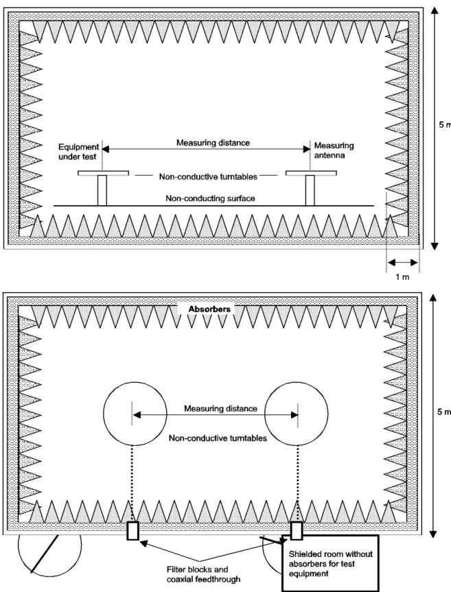
5.1.2 Test site ... 33
5.1.2.1 Open air test site ... 33
5.1.2.1.1 Description ... 33
5.1.2.1.2 Calibration ... 34
5.1.2.2 Anechoic chamber ... 34
5.1.2.2.1 General ... 34
5.1.2.2.2 Description ... 34
5.1.2.2.3 Influence of parasitic reflections ... 37
5.1.2.2.4 Calibration and mode of use ... 37
5.1.2.3 Stripline coupler ... 37 5.1.2.3.0 General ... 37 5.1.2.3.1 Description ... 37 5.1.2.3.2 Calibration ... 37 5.1.2.3.3 Mode of use ... 37 5.1.3 Standard position ... 38
5.1.4 Test antenna of the LT ... 38
5.1.5 Substitution antenna ... 38
5.1.6 Test fixture ... 38
5.1.6.1 Description ... 38
5.1.6.2 Calibration of the test fixture for the measurement of transmitter characteristics ... 39
5.1.6.3 Calibration of the test fixture for the measurement of receiver characteristics ... 39
5.1.6.4 Mode of use ... 40
5.1.7 Equipment with a temporary or internal permanent antenna connector... 40
5.1.7.1 General ... 40
5.1.7.2 Equipment with a temporary antenna connector ... 40
5.1.8.0 General ... 41
5.1.8.1 Description ... 41
5.1.8.2 Test for parasitic reflections ... 41
5.1.8.3 Calibration and mode of use... 42
5.1.9 Lower Tester (LT) ... 42
5.1.9.1 Description ... 42
5.1.9.2 Connections between the EUT and the LT ... 42
5.1.9.3 Functions and abilities... 42
5.1.9.4 Signal generation uncertainty ... 43
5.1.9.5 Modulated DECT-like carrier ... 43
5.1.9.6 CW interferers ... 43
5.1.9.7 DECT RF signal ... 43
5.1.9.8 Test modulation signals ... 43
5.1.10 Upper Tester (UT) ... 43
5.1.10.1 Description of the UT... 43
5.1.10.2 The test standby mode ... 44
5.1.10.3 Test messages ... 44
5.1.10.4 Dummy setting when EUT is a RFP and it is in test stand-by mode... 44
5.1.11 Description of the lower tester FT and PT ... 44
5.1.12 General test methods ... 45
5.1.12.1 General ... 45
5.1.12.2 Sampling the RF signal ... 45
5.1.12.2.1 Introduction ... 45
5.1.12.2.2 Sampling method ... 45
5.1.12.3 Determining the reference position ... 45
5.1.12.3.0 General ... 45
5.1.12.3.1 Case 1: EUTs that cannot transmit ... 45
5.1.12.3.2 Case 2: EUTs that can transmit ... 45
5.1.12.4 Bit error rate (BER) and Frame Error Ratio (FER) measurements ... 45
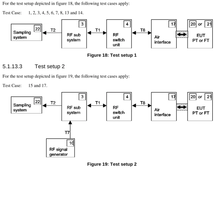
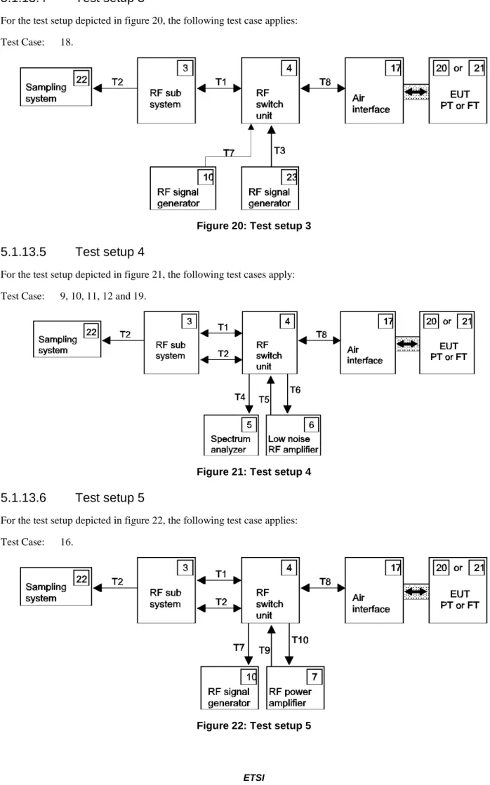
5.1.13 Test setup ... 46 5.1.13.1 General ... 46 5.1.13.2 Test setup 1 ... 46 5.1.13.3 Test setup 2 ... 46 5.1.13.4 Test setup 3 ... 47 5.1.13.5 Test setup 4 ... 47 5.1.13.6 Test setup 5 ... 47
5.1.14 Test arrangements for intermodulation measurements ... 48
5.1.14.1 PT to PT arrangement ... 48
5.1.14.2 FT to FT arrangement ... 48
5.1.14.3 FT to PT arrangement ... 49
5.1.15 Test conditions, power supply and ambient temperatures ... 49
5.1.15.1 General ... 49
5.1.15.2 Nominal test conditions ... 50
5.1.15.3 Extreme test conditions ... 50
5.1.15.4 Test power source - general requirements ... 51
5.1.15.5 Nominal test power source ... 52
5.1.15.5.1 Mains voltage ... 52
5.1.15.5.2 Regulated lead acid battery power sources ... 52
5.1.15.5.3 Nickel cadmium battery... 52
5.1.15.5.4 Other power sources ... 52
5.1.15.6 Extreme test power source ... 52
5.1.15.6.1 Mains voltage ... 52
5.1.15.6.2 Regulated lead acid battery power sources ... 52
5.1.15.6.3 Nickel cadmium battery... 52
5.1.15.6.4 Other power sources ... 52
5.1.15.7 Testing of host connected equipment and plug-in cards ... 52
5.1.15.7.1 Approaches ... 52
5.1.15.7.2 Alternative A: composite equipment ... 53
5.1.15.7.3 Alternative B: use of a test jig and three hosts ... 53
5.3.1.1 Test environment ... 54
5.3.1.2 Method of measurement ... 54
5.3.1.3 Verdict criteria when the EUT is a RFP ... 55
5.3.1.4 Verdict criteria when the EUT is a PP ... 55
5.3.2 Accuracy and stability of timing parameters ... 55
5.3.2.1 Measurement of packet timing jitter ... 55
5.3.2.1.1 Test environment ... 55
5.3.2.1.2 Method of measurement ... 55
5.3.2.1.3 Verdict criteria ... 56
5.3.2.2 Measurement of the reference timing accuracy of a RFP ... 56
5.3.2.2.1 Test environment ... 56
5.3.2.2.2 Method of measurement ... 56
5.3.2.2.3 Verdict criteria ... 56
5.3.2.3 Measurement of packet transmission accuracy of a PP ... 57
5.3.2.3.1 Test environment ... 57 5.3.2.3.2 Method of measurement ... 57 5.3.2.3.3 Verdict criteria ... 57 5.3.3 Transmission burst ... 58 5.3.3.1 Test environment ... 58 5.3.3.2 Method of measurement ... 58 5.3.3.3 Verdict criteria ... 58 5.3.4 Transmitted power ... 59
5.3.4.1 PP and RFP with an integral antenna ... 59
5.3.4.1.1 Test environment ... 59
5.3.4.1.2 Method of measurement ... 59
5.3.4.1.3 Verdict criteria for all EUTs ... 60
5.3.4.2 PP and RFP with external antenna connection(s)... 60
5.3.4.2.1 Test environment ... 60
5.3.4.2.2 Method of measurement ... 60
5.3.4.2.3 Verdict criteria for all EUTs ... 60
5.3.5 RF carrier modulation ... 61
5.3.5.1 Test environment ... 61
5.3.5.2 Method of measurement, parts 1 and 2 ... 61
5.3.5.2.1 Introduction ... 61
5.3.5.2.2 Part 1 ... 61
5.3.5.2.3 Part 2 ... 61
5.3.5.3 Method of measurement, parts 3 and 4 ... 62
5.3.5.3.0 General ... 62
5.3.5.3.1 Part 3 ... 62
5.3.5.3.2 Part 4 ... 62
5.3.5.4 Verdict criteria for part 1 ... 62
5.3.5.5 Verdict criteria for part 2 ... 62
5.3.5.6 Verdict criteria for part 3 ... 63
5.3.5.7 Verdict criteria for part 4 ... 63
5.3.6 Unwanted RF power radiation ... 64
5.3.6.1 General test conditions ... 64
5.3.6.2 Emissions due to modulation ... 64
5.3.6.2.1 Test environment ... 64
5.3.6.2.2 Method of measurement ... 64
5.3.6.2.3 Verdict criteria ... 65
5.3.6.3 Emissions due to transmitter transients ... 66
5.3.6.3.1 Test environment ... 66
5.3.6.3.2 Method of measurement ... 66
5.3.6.3.3 Verdict criteria ... 66
5.3.6.4 Emissions due to intermodulation ... 67
5.3.6.4.1 Test environment ... 67
5.3.6.4.2 Method of measurement ... 67
5.3.6.4.3 Verdict criteria ... 68
5.3.6.5 Spurious emissions when allocated a transmit channel ... 68
5.3.6.5.1 Radiated emissions ... 68
5.3.6.5.2 Conducted spurious emissions when the EUT has a permanent external antenna connector ... 69
5.3.7.1 Radio receiver sensitivity ... 70
5.3.7.1.1 Test environment ... 70
5.3.7.1.2 Method of measurement ... 70
5.3.7.1.3 Verdict criteria ... 71
5.3.7.2 Radio receiver reference BER and FER ... 71
5.3.7.2.1 Test environment ... 71
5.3.7.2.2 Method of measurement ... 71
5.3.7.2.3 Verdict criteria ... 71
5.3.7.3 Radio receiver interference performance ... 71
5.3.7.3.1 Test environment ... 71
5.3.7.3.2 Method of measurement ... 71
5.3.7.3.3 Verdict criteria ... 72
5.3.7.4 Radio receiver blocking case 1: owing to signals occurring at the same time but on other frequencies ... 72
5.3.7.4.1 Test environment ... 72
5.3.7.4.2 Method of measurement ... 72
5.3.7.4.3 Verdict criteria ... 73
5.3.7.5 Radio receiver blocking case 2: owing to signals occurring at a different time ... 74
5.3.7.5.1 Test environment ... 74
5.3.7.5.2 Method of measurement ... 74
5.3.7.5.3 Verdict criteria ... 74
5.3.7.6 Receiver intermodulation performance ... 74
5.3.7.6.1 Test environment ... 74
5.3.7.6.2 Method of measurement ... 75
5.3.7.6.3 Verdict criteria ... 75
5.3.7.7 Spurious emissions when the PP has no allocated transmit channel ... 75
5.3.7.7.1 Test environment ... 75
5.3.7.7.2 Method of measurement ... 75
5.3.7.7.3 Verdict criteria (outside the DECT band) ... 76
5.3.7.7.4 Verdict criteria (inside the DECT band) ... 76
5.3.8 Channel access ... 76 5.3.9 WRS testing ... 76 5.3.9.0 General ... 76 5.3.9.1 Testing as a PP ... 76 5.3.9.2 Testing as an RFP ... 76 5.3.9.3 Additional requirements ... 77
5.3.10 Requirements for PPs with direct PP to PP communication mode ... 77
5.3.10.0 General ... 77
5.3.10.1 Setting the EUT in direct communications mode ... 77
5.3.10.2 When the EUT has not initiated a call ... 77
5.3.10.3 When the EUT initiates a call ... 77
5.3.10.4 Applicants declarations ... 78 5.3.11 Distributed Communications ... 78 5.3.11.0 General ... 78 5.3.11.1 Testing as a PP ... 78 5.3.11.2 Testing as an RFP ... 78 5.3.11.3 Applicants declaration ... 79
5.3.12 Higher level modulation options ... 79
5.3.12.0 General ... 79
5.3.12.1 Activation of higher level modulations when EUT is in test stand-by mode ... 80
5.3.12.2 Applicants declaration ... 80
Annex A (normative):
Relationship between the present document and the essential
requirements of Directive 2014/53/EU ... 81
Annex B (normative):
Procedures for test fixture calibration and for measurement of
radiated spurious emissions ... 83
B.1
Calibration of test fixture for receiver measurements ... 83
B.2 Radiated
measurements
... 84
B.2.1 General ... 84
B.2.2 Radiated spurious emissions... 85
B.2.2.1 Definition ... 85
B.2.2.2 Method of measurement ... 85
B.2.3 Cabinet radiation ... 87
B.2.3.1 Definition ... 87
B.2.3.2 Method of measurement ... 87
Annex C (normative):
Procedure for measurement of conducted spurious emissions ... 88
C.1 Conducted
spurious
emissions
... 88
C.1.1 Definition ... 88
C.1.2 Method of measurement ... 88
Annex D (normative):
Measurement of BER and FER ... 89
Annex E (informative):
Procedures for the measurement of synchronization loss at the EUT
by the LT ... 90
E.1 Description
... 90
E.2 Method
... 90
Annex F (informative):
Bibliography ... 91
Intellectual Property Rights
IPRs essential or potentially essential to the present document may have been declared to ETSI. The information pertaining to these essential IPRs, if any, is publicly available for ETSI members and non-members, and can be found in ETSI SR 000 314: "Intellectual Property Rights (IPRs); Essential, or potentially Essential, IPRs notified to ETSI in respect of ETSI standards", which is available from the ETSI Secretariat. Latest updates are available on the ETSI Web server (https://ipr.etsi.org/).
Pursuant to the ETSI IPR Policy, no investigation, including IPR searches, has been carried out by ETSI. No guarantee can be given as to the existence of other IPRs not referenced in ETSI SR 000 314 (or the updates on the ETSI Web server) which are, or may be, or may become, essential to the present document.
Foreword
This Harmonised European Standard (EN) has been produced by ETSI Technical Committee Digital Enhanced Cordless Telecommunications (DECT).
The present document has been prepared under the Commission's standardisation request C(2015) 5376 final [i.16] to provide one voluntary means of conforming to the essential requirements of Directive 2014/53/EU on the harmonisation of the laws of the Member States relating to the making available on the market of radio equipment and repealing Directive 1999/5/EC [8].
Once the present document is cited in the Official Journal of the European Union under that Directive, compliance with the normative clauses of the present document given in table A.1 confers, within the limits of the scope of the present document, a presumption of conformity with the corresponding essential requirements of that Directive and associated EFTA regulations.
National transposition dates
Date of adoption of this EN: 22 April 2016
Date of latest announcement of this EN (doa): 31 July 2016 Date of latest publication of new National Standard
or endorsement of this EN (dop/e): 31 January 2017 Date of withdrawal of any conflicting National Standard (dow): 31 January 2018
Modal verbs terminology
In the present document "shall", "shall not", "should", "should not", "may", "need not", "will", "will not", "can" and "cannot" are to be interpreted as described in clause 3.2 of the ETSI Drafting Rules (Verbal forms for the expression of provisions).
1 Scope
The present document applies to the following equipment types for the Digital Enhanced Cordless Telecommunications (DECT) common interface:
a) Fixed Part (FP); b) Portable Part (PP);
c) Cordless Terminal Adapter (CTA);
d) Wireless Relay Station (WRS) (FP and PP combined);
e) Hybrid Part (HyP) (a PP with capability to act as a FP to provide PP to PP communication).
These radio equipment types are capable of operating in all or any part of the frequency bands given in table 1. Table 1: Radiocommunications service frequency bands
Radiocommunications service frequency bands
Transmit 1 880 MHz to 1 900 MHz
Receive 1 880 MHz to 1 900 MHz
The DECT service frequency band for transmitting and receiving for all elements is 1 880 MHz to 1 900 MHz. Details of the DECT Common Interface may be found in ETSI EN 300 175-1 [i.10], ETSI EN 300 175 parts 2 to 3 [1] to [2], ETSI EN 300 175-4 [i.11], ETSI EN 300 175 parts 5 to 6 [3] to [4], and ETSI EN 300 175 parts 7 to 8 [i.12] to [i.13]. Further details of the DECT system may be found in the ETSI Technical Reports, ETSI TR 101 178 [i.1] and ETSI ETR 043 [i.2]. Information about ULE may be found in the ETSI Technical Specifications ETSI
TS 102 939-1 [i.14] and ETSI TS 102 939-2 [i.15].
The present document contains requirements to demonstrate that radio equipment both effectively uses and supports the efficient use of radio spectrum in order to avoid harmful interference.
2 References
2.1 Normative
references
References are either specific (identified by date of publication and/or edition number or version number) or
non-specific. For specific references, only the cited version applies. For non-specific references, the latest version of the referenced document (including any amendments) applies.
Referenced documents which are not found to be publicly available in the expected location might be found at http://docbox.etsi.org/Reference.
NOTE: While any hyperlinks included in this clause were valid at the time of publication, ETSI cannot guarantee their long term validity.
The following referenced documents are necessary for the application of the present document.
[1] ETSI EN 300 175-2 (V2.6.1) (07-2015): "Digital Enhanced Cordless Telecommunications (DECT); Common Interface (CI); Part 2: Physical layer (PHL)".
[2] ETSI EN 300 175-3 (V2.6.1) (07-2015): "Digital Enhanced Cordless Telecommunications (DECT); Common Interface (CI); Part 3: Medium Access Control (MAC) Layer". [3] ETSI EN 300 175-5 (V2.6.1) (07-2015): "Digital Enhanced Cordless Telecommunications
(DECT); Common Interface (CI); Part 5: Network (NWK) layer".
[4] ETSI EN 300 175-6 (V2.6.1) (07-2015): "Digital Enhanced Cordless Telecommunications (DECT); Common Interface (CI); Part 6: Identities and addressing".
[5] Void.
[6] ETSI EN 300 700 (V1.2.1) (09-2000): "Digital Enhanced Cordless Telecommunications (DECT); Wireless Relay Station (WRS)".
[7] Recommendation ITU-T O.153 (1992): "Basic parameters for the measurement of error performance at bit rates below the primary rate".
[8] Directive 2014/53/EU of the European Parliament and of the Council of 16 April 2014 on the harmonisation of the laws of the Member States relating to the making available on the market of radio equipment and repealing Directive 1999/5/EC.
2.2 Informative
references
References are either specific (identified by date of publication and/or edition number or version number) or
non-specific. For specific references, only the cited version applies. For non-specific references, the latest version of the referenced document (including any amendments) applies.
NOTE: While any hyperlinks included in this clause were valid at the time of publication, ETSI cannot guarantee their long term validity.
The following referenced documents are not necessary for the application of the present document but they assist the user with regard to a particular subject area.
[i.1] ETSI TR 101 178: "Digital Enhanced Cordless Telecommunications (DECT); A High Level Guide to the DECT Standardization".
[i.2] ETSI ETR 043: "Digital Enhanced Cordless Telecommunications (DECT); Common Interface (CI); Services and facilities requirements specification".
[i.3] Void. [i.4] Void. [i.5] Void. [i.6] Void. [i.7] Void.
[i.8] ETSI TR 100 028: "Electromagnetic compatibility and Radio spectrum Matters (ERM); Uncertainties in the measurement of mobile radio equipment characteristics".
[i.9] ISO/IEC 9646-1 (1994): "Information technology; Open Systems Interconnection; Conformance testing methodology and framework; Part 1: General concepts".
[i.10] ETSI EN 300 175-1 (V2.6.1) (07-2015): "Digital Enhanced Cordless Telecommunications (DECT); Common Interface (CI); Part 1: Overview".
[i.11] ETSI EN 300 175-4 (V2.6.1) (07-2015): "Digital Enhanced Cordless Telecommunications (DECT); Common Interface (CI); Part 4: Data Link Control (DLC) Layer".
[i.12] ETSI EN 300 175-7 (V2.6.1) (07-2015): "Digital Enhanced Cordless Telecommunications (DECT); Common Interface (CI); Part 7: Security features".
[i.13] ETSI EN 300 175-8 (V2.6.1) (07-2015): "Digital Enhanced Cordless Telecommunications (DECT); Common Interface (CI); Part 8: Speech and audio coding and transmission".
[i.14] ETSI TS 102 939-1: "Digital Enhanced Cordless Telecommunications (DECT); Ultra Low Energy (ULE); Machine to Machine Communications; Part 1: Home Automation Network (phase 1)". [i.15] ETSI TS 102 939-2: "Digital Enhanced Cordless Telecommunications (DECT); Ultra Low Energy
[i.16] Commission Implementing Decision C(2015) 5376 final of 4.8.2015 on a standardisation request to the European Committee for Electrotechnical Standardisation and to the European
Telecommunications Standards Institute as regards radio equipment in support of Directive 2014/53/EU of the European Parliament and of the Council.
3
Definitions, symbols and abbreviations
3.1 Definitions
For the purposes of the present document, the following terms and definitions apply:
antenna diversity: feature that implies that the Radio Fixed Part (RFP) is able to select for each bearer independently
different antenna properties such as gain, polarization, coverage patterns, and other features that may affect the practical coverage
NOTE: A typical example is space diversity, provided by two vertically polarized antennas separated by 10 cm to 20 cm.
bearer handover: internal handover process provided by the Medium Access Control (MAC) layer, whereby one MAC
connection can modify its underlying bearers while maintaining the service provided to the Data Link Control (DLC) layer
NOTE: Bearer handover is slot based.
cell: domain served by a single antenna system (including a leaky feeder) of one FP
NOTE: A cell may include more than one source of radiated Radio Frequency energy (i.e. more than one Radio End Point).
Central Control Fixed Part: physical grouping that contains the central control elements of one or several FPs
NOTE: An FP may be split in the control part (CCFP) and the Radio part (RFP). A CCFP may control one or more RFPs.
conducted measurements: measurements which are made using a direct connection to the equipment under test Cordless Terminal Adapter: physical grouping that contains a DECT portable termination and a line interface DECT Distributed communications: communication capability of a DECT Local Network that allows a number of
DECT terminals (a FP and number of PPs) to co-exist and directly communicate one with another
DECT-like carrier: modulated RF DECT carrier used for interference testing which conforms to the requirements in
ETSI EN 300 175-2 [1] in terms of frequency and timing and uses a pseudo-random sequence for modulation
double slot: one 12th of a Time Division Multiple Access (TDMA) frame which is used to support one high capacity
physical channel
duplex bearer: use of two simplex bearers operating in opposite directions on two physical channels
NOTE: These pairs of channels always use the same RF carrier and always use evenly spaced slots (i.e. separated by 0,5 TDMA frame).
environmental profile: range of environmental conditions under which equipment within the scope of the present
document is required to comply with the provisions of the present document
Equipment Under Test: equipment submitted to the test laboratory for type examination
Fixed Part (DECT Fixed Part): physical grouping that contains all of the elements in the DECT network between the
local network and the DECT air interface
NOTE: A DECT FP contains the logical elements of at least one Fixed radio Termination (FT), plus additional implementation specific elements.
Fixed radio Termination: logical group of functions that contains all of the DECT processes and procedures on the
fixed side of the DECT air interface
NOTE: A FT only includes elements that are defined in the DECT CI standard. This includes radio transmission elements (layer 1) together with a selection of layer 2 and layer 3 elements.
full slot: one 24th of a TDMA frame which is used to support one physical channel
half slot: one 48th of a TDMA frame which is used to support one physical channel
handover: process of switching a call in progress from one physical channel to another physical channel
NOTE: These processes can be internal or external. There are two physical forms of handover: intra-cell handover and inter-cell handover. Intra-cell handover is always internal. Inter-cell handover can be internal or external.
host equipment: any equipment which has a complete user functionality when not connected to the DECT radio
equipment, and to which the DECT radio equipment provides additional functionality, and to which connection is necessary for the DECT radio equipment to offer functionality
Hybrid Part: DECT terminal that provides FT, as well as, PT capabilities being capable of communicating directly
with FT or PT
inter-cell handover: switching of a call in progress from one cell to another cell
NOTE: This only defines the form of handover, it does not define a specific process.
intra-cell handover: switching of a call in progress from one physical channel of one cell to another physical channel
of the same cell
NOTE: This only defines the form of handover, it does not define a specific process.
long slot: name given to the variable capacity slot when j = 640 or j = 672. The long slot has an intermediate size
between the full slot and the double slot
Lower Tester: logical grouping that contains the test equipment, a functionally equivalent DECT PT, a functionally
equivalent DECT FT and a test controller
multiframe: repeating sequence of 16 successive TDMA frames, that allows low rate or sporadic information to be
multiplexed (e.g. basic system information or paging)
physical channel: simplex channel that is created by transmitting in one particular slot on one particular RF channel in
successive TDMA frames (see also simplex bearer)
NOTE: One physical channel provides a simplex service. Two physical channels are required to provide a duplex service.
Portable Handset: single physical grouping that contains all of the portable elements that are needed to provide a
teleservice to the user
NOTE: PHS is a subset of all possible PPs. This subset includes all physical groupings that combine one PT plus at least one portable application in a single physical box.
Portable Part: physical grouping that contains all elements between the user and the DECT air interface
NOTE: PP is a generic term that may describe one or several physical pieces. A PP is logically divided into one PT plus one or more portable applications.
Portable radio Termination: logical group of functions that contains all of the DECT processes and procedures on the
portable side of the DECT air interface
NOTE: A PT only includes elements that are defined in the DECT CI standard ETSI EN 300 175 parts 2 to 3 [1] to [2] and ETSI EN 300 175 parts 5 to 6 [3] to [4]. This includes radio transmission elements together with a selection of layer 2 and layer 3 elements.
Radio End Point: physical grouping that contains one radio transmitter/receiver, fixed or portable
NOTE: A REP may operate only as a receiver or only as a transmitter.
Radio Fixed Part: one physical sub-group of a FP that contains all the REPs (one or more) that are connected to a
single system of antennas
simplex bearer: MAC layer service that is created using one physical channel
TDMA frame: time-division multiplex of 10 ms duration, containing 24 successive full slots
NOTE: A TDMA frame starts with the first bit period of full slot 0 and ends with the last bit period of full slot 23.
test laboratory: body which performs conformance testing
NOTE: This laboratory is accredited to perform 3rd party testing.
test load: substantially non-reactive, non-radiating power attenuator which is capable of safely dissipating the power
from the transmitter(s)
Upper Tester: logical grouping that controls the EUT when under test
NOTE: Commands are sent from the LT to the UT to place the EUT in the appropriate test mode.
variable capacity slot: slot structure that allows implementing slot lengths different of the half, full and double
structures. A variable capacity slot may have a duration of 100+j or 104+j data symbols with j ranging from zero to 856
3.2 Symbols
For the purposes of the present document, the following symbols apply: dB deciBel
BT Bandwidth Time product
dBi dB isotropic
dBm dB relative to 1 mW
PNTP Maximum transmit power per simultaneously active transceiver
3.3 Abbreviations
For the purposes of the present document, the following abbreviations apply:
AM Amplitude Modulation
ARI Access Rights Identity BER Bit Error Ratio
CCFP Central Control Fixed Part
CI Common Interface
CRC Cyclic Redundancy Check
CTA Cordless Terminal Adapter
CW Continuous Wave
D8PSK Differential 8 Phase Shift Keying DBPSK Differential Binary Phase Shift Keying DQPSK Differential Quaternary Phase Shift Keying EIRP Equivalent Isotropically Radiated Power EMC ElectroMagnetic Compatibility
emf electro-motive force
ERP Effective Radiated Power EUT Equipment Under Test
FER Frame Error Ratio
FP Fixed Part
FT Fixed radio Termination
GFSK Gaussian Frequency Shift Keying
HyP Hybrid Part
LV Low Voltage MAC Medium Access Control NTP Normal Transmitted Power
PHL PHysical Layer
PHS Portable HandSet
PIXIT Protocol Implementation eXtra Information for Testing
PP Portable Part
ppm parts per million
PT Portable radio Termination
QAM Quadrature Amplitude Modulation R&TTE Radio and Telecommunications Terminal Equipment REP Radio End Point
RF Radio Frequency
RFP Radio Fixed Part
RFPI Radio Fixed Part Identity
RH Relative Humidity
TDMA Time Division Multiple Access TSM Test Standby Mode
TSP Test Support Profile ULE Ultra Low Energy
UT Upper Tester
VSWR Voltage Standing Wave Ratio WRS Wireless Relay Station
4
Technical requirements specifications
4.1 Environmental
profile
The technical requirements of the present document apply under the environmental profile for operation of the equipment, which shall be declared by the supplier. The equipment shall comply with all the technical requirements of the present document at all times when operating within the boundary limits of the required operational environmental profile.
4.2 Overview
4.2.0 General
The test cases described in these clauses are intended to follow the ISO/IEC 9646-1 [i.9] recommendations as closely as possible. However, for practical reasons it is not always possible to follow the guidelines exactly and the following clauses describe the relationship of the present document to ISO/IEC 9646-1 [i.9].
4.2.1 Test
suites
The term "test suite" is defined in ISO/IEC 9646-1 [i.9].
Table 2 lists the test suite that is described in the present document and the test groups that are associated with it. Table 2: Test suite
Test suite Test groups
DECT Physical Layer (PHL) PHL services
Transmission of physical packets Reception of physical packets
WRS PP to PP communication
Direct communication
4.2.2 Test
groups
The term "test group" is defined in ISO/IEC 9646-1 [i.9].
Table 3 lists the test groups that are described in the present document and the test cases that are associated with them. Table 3: Test groups
Test group Test cases
Physical layer services 1 2 4
Transmission of physical packets 5 6 7 8 9 10 11 12
Reception of physical packets 13 14 15 16 17 18 19
Channel access 20
WRS 21
PP to PP communication 22
Direct communication 23
Higher level modulation 24
4.2.3 Test
cases
The term "test case" is defined in ISO/IEC 9646-1 [i.9] , clause 3.3. Table 4 lists the test cases that are described in the present document.
Table 4: Test cases
Test case Test case Clause number
1 Accuracy and stability of RF carriers 4.5.1
2 Timing jitter: slot-slot on the same channel 4.5.2
3 Reference timing accuracy of a RFP
4 Measurement of packet timing accuracy
5 Transmission Burst 4.5.3
6 Transmitted power: PP and RFP with an integral antenna 4.5.4.1.1
7 Transmitted power: PP and RFP with an external antenna connector 4.5.4.1.2
8 RF carrier modulation 4.5.5
9 Emissions due to modulation 4.5.6.2
10 Emissions due to transmitter transients 4.5.6.3
11 Emissions due to intermodulation 4.5.6.4
12 Spurious emissions when allocated a transmit channel 4.5.6.5
13 Radio receiver sensitivity 4.5.7.1
14 Radio receiver reference bit error ratio 4.5.7.2
15 Radio receiver interference performance 4.5.7.3
16 Radio receiver blocking case 1 4.5.7.4
17 Radio receiver blocking case 2 4.5.7.5
18 Receiver intermodulation performance 4.5.7.6
19 Spurious emissions when the radio endpoint has no allocated transmit channel 4.5.7.7 20 Channel access 4.5.8 21 WRS 4.5.119 22 PP to PP communication 4.5.10 23 Direct communication 4.5.11
24 Higher level modulation 4.5.12
4.3 Applicant's
declaration
Where parameters, capabilities, etc., are subject to applicant's declaration and not a specific test, it shall be the applicant's responsibility to supply a declaration of implementation, in which the applicant explicitly affirms the implementation in the equipment of certain parameters and capabilities.
4.4
Applicability of tests
4.4.0 Introduction
The applicability of the individual test suits in the present document is dependent on the type of equipment. Equipment may contain one or more of the features listed in the following clauses. It is assumed that all equipment contains a radio receiver. The tests described in the present document shall only be applied to the equipment physically containing a DECT RF receiver and/or transceiver. Control lines to the EUT necessary for its operation shall be permitted.
4.4.1
Equipment that includes only a DECT RF receiver
The tests are specified in clause 5.3.7.
4.4.2
Equipment that includes a radio transmitter
The tests are specified in clauses 5.3.1, 5.3.2, 5.3.3, 5.3.4, 5.3.5, 5.3.6, 5.3.7 and 5.3.8. For equipment continuously transmitting (e.g. FP with dummy bearer) the test specified in clause 5.3.7.7 shall not apply.
4.4.3 CTAs
The requirements for PPs apply to Cordless Terminal Adapters, CTAs.
4.4.4
Equipment with combined FT and PT functionality
4.4.4.0 General
Equipment that is able to operate both as an RFP and as a PP shall generally meet the conformance requirements of the present document for an RFP when operating as an RFP and for a PP when operating as a PP.
There are however three basic types of equipment with combined FT and PT functionality using a single common radio, which have been standardized. The notations for these types of equipment are Wireless Relay Stations, WRSs, see ETSI EN 300 700 [6], Direct PP to PP communication, see ETSI EN 300 175-3 [2], annex G, and Distributed
Communications, see ETSI EN 300 175-5 [3], annex I. For these the following requirements apply.
4.4.4.1
Wireless Relay Station
Wireless Relay Stations, WRSs, see ETSI EN 300 700 [6], provide relaying between FT and PT operating simultaneously. A WRS belongs to a specific DECT system, and has to be registered and locked to this system to operate.
WRSs shall conform to the requirements of clause 4.5.9.
NOTE: Conformance to clause 4.5.9 is also relevant for telephony applications. A WRS conforms to a defined frame multiplexing scheme, see ETSI EN 300 700 [6], which provides a transparent digital bit pipe for the user data, and which automatically provides an acceptable upper bound of the incremental delay introduced by a WRS.
4.4.4.2
Direct PP to PP communication
Direct PP to PP communication, see ETSI EN 300 175-3 [2], annex G, is a notation for a PP (or CTA) feature that provides ad hoc networking with specific temporary system ad hoc identities. A PP temporarily switches into FT mode to provide direct access to any of the other PPs of the ad hoc network. There is no requirement or need to being locked to an RFP. Since no RFP is involved in the communication link, direct PP to PP communication only uses half the spectrum compared to normal calls routed via RFPs.
4.4.4.3 Distributed
Communications
Distributed communications, ETSI EN 300 175-5 [3], annex I, is a notation for a DECT system feature providing direct links between PPs (or CTAs). Such PPs and CTAs are also called Hybrid Parts, HyP. The HyPs always stay in lock with the DECT system and an RFP is always involved in the direct link connection. Either just by providing the locking and time synchronization, or also by direct involvement in the set up procedure. The main target application is data local networking. Since no RFP is involved in the user communication link, the distributed communications option only uses half the spectrum compared to normal calls routed via RFPs.
PPs and CTAs with distributed communications option, HyPs, shall conform to the requirements of clause 4.5.11.
4.4.5
Provision of 4 Mbit/s services. Equipment that is capable of using
higher level modulation
Equipment is allowed to use 4-level, 8-level, 16-level and/or 64-level modulation in addition to the mandatory 2-level modulation. This will increase the bit rate of single radio DECT equipment by a factor 2 to 6, which allows for 4 Mbit/s services.
Such equipment shall conform to the requirements of clause 4.5.12.
4.4.6
Equipment supporting additional carriers
For EUTs supporting additional carriers (see clause 4.5.1.1) the various tests cases shall be performed, where relevant, on the two band edge carriers and on one carrier inside the band.
4.5 Conformance
requirements
4.5.1
Accuracy and stability of RF carriers
4.5.1.1 Definition
Ten RF carriers shall be placed into the frequency band 1 880 MHz to 1 900 MHz with centre frequencies Fc given by: Fc = F0 - c x 1,728 MHz;
where
F0 = 1 897,344 MHz; and
c = 0,1, ..., 9.
Above this band, additional carriers are defined with centre frequencies Fc given by: Fc = F9 + c x 1,728 MHz;
and c ≥ 10 and RF band = 00001 (see ETSI EN 300 175-3 [2], clause 7.2.3.3).
The frequency band between Fc - 1,728/2 MHz and Fc + 1,728/2 MHz shall be designated RF channel c. NOTE: A nominal DECT RF carrier is one whose centre frequency is generated by the formula:
Fg = F0 - g x 1,728 MHz, where g is any integer.
All DECT equipment shall be capable of working on all 10 RF channels, c = 0,1, ..., 9.
4.5.1.2 Limits
4.5.1.3 Conformance
Conformance tests as defined in clause 5.3.1 shall be carried out.
4.5.2
Accuracy and stability of timing parameters
4.5.2.0 General
The requirements are given in ETSI EN 300 175-2 [1], clauses 4.2.1, 4.2.2, 4.2.3 and 4.2.4.
4.5.2.1 Definitions
4.5.2.1.1 Slot
structure
To access the medium in time, a regular TDMA structure is used. The structure repeats in frames of 11 520 symbols, and the data is transmitted at a symbol rate of 1 152 ksymbol/s. Within this frame 24 full-slots are created, each consisting of two half-slots. A double slot has a length of two full slots, and starts concurrently with a full slot. The detailed slot structure is defined in in ETSI EN 300 175-2 [1], clause 4.2.1.
4.5.2.1.2
Definition of the position of p0
The start of bit p0 is defined to occur at the point in time 16 bit periods before the instant at which the modulated carrier passes through the nominal channel frequency immediately prior to the deviation corresponding to the first bit of the packet synchronization word for the EUT as defined in ETSI EN 300 175-2 [1], clause 4.6, of for a PT or FT. A method shall be used for the determination of the position of the packet synchronization word which meets the measurement uncertainty stated in clause 5.2. It is not the point at which a receiver determines the presence of p0.
4.5.2.2 Limits
The requirements are given in ETSI EN 300 175-2 [1], clauses 4.2.2, 4.2.3 and 4.2.4.
4.5.2.3 Conformance
Conformance tests as defined in clause 5.3.2 shall be carried out.
4.5.3 Transmission
burst
4.5.3.1 Definitions
4.5.3.1.1 Physical
packets
The term "physical packet" used in the present document refers to all the bits transmitted by the DECT REP in one slot time. The timing of the physical packet relative to the power-time template shall be conditioned by the absolute packet timing measurement uncertainty in clause 5.2.
4.5.3.1.2 Transmitted
power
This is the mean power delivered over one radio frequency cycle.
4.5.3.1.3
Normal Transmitted Power (NTP)
The NTP is the transmitted power averaged from the start of bit p0 of the physical packet to the end of the physical packet.
4.5.3.1.4
Transmitter attack time
This is the time taken for the transmitted power to increase from 25 μW to the time that the first bit of the physical packet, p0, starts transmission.
4.5.3.1.5
Transmitter release time
This is the time, taken from the end of the physical packet, for the transmitted power to decrease to 25 μW. The transmitter release time shall be less than 10 μs.
4.5.3.1.6 Minimum
power
From the first bit of the packet, p0, to the end of the physical packet, the transmitted power as measured shall be greater than (NTP - 1 dB).
4.5.3.1.7 Maximum
power
From 10 μs after the start of bit p0 to 10 μs after the end of the physical packet the transmitted power as measured shall be less than (NTP + 1 dB).
From 10 μs before the start of bit p0 to 10 μs after the start of bit p0 the transmitted power as measured shall be less than (NTP + 4 dB), and shall be less than 315 mW plus the maximum allowed measurement uncertainty as described in clause 5.2.
4.5.3.1.8
Maintenance of transmission after packet end
The transmitted power as measured shall be maintained greater than (NTP - 6 dB) for 0,5 μs after the end of the physical packet.
4.5.3.1.9
Transmitter idle power output
For the time period starting 27 μs after the end of the physical packet, and finishing 27 μs before the next transmission of data bit p0, the transmitter idle power shall be less than 20 nW plus the maximum allowed measurement uncertainty as described in clause 5.2. This requirement shall apply except when p0 of the next transmitted packet occurs less than 54 μs after the end of the transmitted physical packet.
4.5.3.2 Limits
The requirements are given in clause 5.2 of ETSI EN 300 175-2 [1].
4.5.3.3 Conformance
Conformance tests as defined in clause 5.3.3 shall be carried out.
4.5.4 Transmitted
power
4.5.4.1 Definitions
4.5.4.1.0
Transceiver and P
NTPdefinitions
4.5.4.1.0.1 Nominal transceiver definition
All occurrences of the term "transceiver" in the present document, unless otherwise specifically indicated, shall be understood as referring to a "nominal transceiver" with the following definition:
"Nominal transceiver" is the electronic system or part of a system, able to transmit and receive radio signals in the frequency interval equivalent to a single DECT radio channel.
A DECT radio channel is defined as any 1 728 MHz frequency interval centred in any of the DECT carrier frequencies defined in ETSI EN 300 175-2 [1], clause 4.1.1.
Any electronic system able to transmit and receive radio signals simultaneously in an interval of more than one DECT radio channel is considered a multiple transceiver system for the purpose of the present document, irrespective of the physical implementation.
4.5.4.1.0.2 PNTP definition
PNTP is defined as the maximum transmit power in a given instant of time per simultaneously active nominal transceiver.
4.5.4.1.1
PP and RFP with an integral antenna
The NTP shall be less than PNTP per simultaneously active transceiver at nominal conditions. The power measured at a temporary connector is the NTP.
4.5.4.1.2
PP and RFP with external connections for all antennas
For a radio end point with more than one antenna port, the instantaneous power from each antenna port shall be added together to give the NTP.
The NTP shall be less than PNTP per simultaneously active transceiver.
4.5.4.1.3
PP and RFP with both integral and external antennas
If the integral and external antennas are not transmitting simultaneously then the test cases described in clauses 5.3.4.1 and 5.3.4.2 shall be applied independently. The appropriate antenna is selected using the test message referenced in clause 5.1.10.3.
If the integral and external antennas are transmitting simultaneously then both clauses 5.3.4.1 and 5.3.4.2 shall be applied and the results shall be added to give the NTP.
4.5.4.2 Limits
PNTP is 250 mW, equal to 24 dBm. The antenna gain of integral antennas shall be less than (12 dBi + X). X is the difference in dB between 24 dBm and the NTP expressed in dBm for any one active transceiver. The antenna gain of (12 dBi + X) corresponds to an EIRP of 4W (36 dBm).
4.5.4.3 Conformance
Conformance tests as defined in clause 5.3.4 shall be carried out.
4.5.4.4 Multi-transceiver
systems
For systems implementing multiple transceivers, with the definition of transceiver given in clause 4.5.4.1.0.1, the limit of 250 mW, 24 dBm shall be understood as per nominal transceiver. In case of simultaneous transmission over several DECT radio channels on the same time interval, the compound power will be the combination of the PNTP of each simultaneously active nominal transceiver.
4.5.5
RF carrier modulation
4.5.5.1 Definition
The modulation method shall be Gaussian Frequency Shift Keying (GFSK) with a bandwidth-bit period product of nominally 0,5 and a nominal peak deviation (f) of 288 kHz.
A binary "1" is encoded with a peak frequency deviation of (+f), giving a peak transmit frequency of (Fc + f), which is greater than the carrier frequency of (Fc). A binary "0" is encoded with a peak frequency deviation of (-f), giving a peak transmit frequency of (Fc - f).
For High level modulation options, see clause 4.5.12.
4.5.5.2 Limits
The requirements are given in ETSI EN 300 175-2 [1], clause 5.4.3.
4.5.5.3 Conformance
4.5.6
Unwanted RF power radiation
4.5.6.1 General
If the EUT is equipped with antenna diversity, the EUT shall have the diversity operation defeated for the following tests (see clause 5.1.10.3 for the appropriate test message reference).
4.5.6.2
Emissions due to modulation
4.5.6.2.1 Definition
The unwanted emission(s) due to modulation is the power measured in any DECT RF channel other than the one in which the EUT is transmitting, integrated over a bandwidth of 1 MHz.
4.5.6.2.2 Limits
The requirements are given in ETSI EN 300 175-2 [1], clause 5.5.1.
4.5.6.2.3 Conformance
Conformance tests as defined in clause 5.3.6.2 shall be carried out.
4.5.6.3
Emissions due to transmitter transients
4.5.6.3.1 Definition
The power level of all modulation products (including AM components due to the switching on or off of the modulated RF carrier) in a DECT RF channel as a result of a transmission on another DECT RF channel.
4.5.6.3.2 Limits
The requirements are given in ETSI EN 300 175-2 [1], clause 5.5.2.
4.5.6.3.3 Conformance
Conformance tests as defined in clause 5.3.6.3 shall be carried out.
4.5.6.4
Emissions due to intermodulation
4.5.6.4.1 Definition
The power level of intermodulation products that are on any DECT physical channel when any combination of the transmitters at a radio FP or portable part are in calls on the same slot on different frequencies.
4.5.6.4.2 Limits
The requirements are given in ETSI EN 300 175-2 [1], clause 5.5.3.
4.5.6.4.3 Conformance
Conformance tests as defined in clause 5.3.6.4 shall be carried out.
4.5.6.5
Spurious emissions when allocated a transmit channel
4.5.6.5.1 Definition
The peak power level of any RF emissions outside the radio frequency band allocated to DECT when a radio endpoint has been allocated a transmit channel. If a REP has more than one transceiver, any out of band transmitter
intermodulation products shall also be included.
The limits and conformance requirements cover two kinds of emissions, radiated and conducted spurious emissions.
4.5.6.5.2 Limits
4.5.6.5.3 Conformance
Conformance tests as defined in clause 5.3.6.5 shall be carried out.
4.5.7
Radio receiver testing
4.5.7.1
Radio receiver sensitivity
4.5.7.1.1 Definition
The radio receiver sensitivity is defined as the power level at the receiver input at which the Bit Error Ratio (BER) is 0,001. The radio receiver sensitivity shall be 60 dBμV/m (-83 dBm) or better.
4.5.7.1.2 Limits
The requirements are given in ETSI EN 300 175-2 [1], clause 6.2.
4.5.7.1.3 Conformance
Conformance tests as defined in clause 5.3.7.1 shall be carried out.
4.5.7.2
Radio receiver reference BER and FER
4.5.7.2.1 Definition
The radio receiver reference BER and FER is the maximum allowed BER and FER for a power level at the receiver input of -73 dBm or greater (i.e. 70 dBμV/m).
4.5.7.2.2 Limits
The requirements are given in clause 6.3 of ETSI EN 300 175-2 [1].
4.5.7.2.3 Conformance
Conformance tests as defined in clause 5.3.7.2 shall be carried out.
4.5.7.3
Radio receiver interference performance
4.5.7.3.1 Definition
The ability of DECT equipment to continue receiving in the presence of an interfering signal on the same or different DECT RF channel.
4.5.7.3.2 Limits
The requirements are given in ETSI EN 300 175-2 [1], clause 6.4.
4.5.7.3.3 Conformance
Conformance tests as defined in clause 5.3.7.3 shall be carried out.
4.5.7.4
Radio receiver blocking case 1: owing to signals occurring at the same time
but on other frequencies
4.5.7.4.1 Definition
The receiver should work in the presence of strong signals on other frequencies. These interferers may be modulated carriers or single continuous - wave carriers.
4.5.7.4.2 Limits
4.5.7.4.3 Conformance
Conformance tests as defined in clause 5.3.7.4 shall be carried out.
4.5.7.5
Radio receiver blocking case 2: owing to signals occurring at a different time
4.5.7.5.1 Definition
When a high level interferer is present in a physical channel other than the one the receiver is on, the receiver is able to continue receiving the desired signal.
4.5.7.5.2 Limits
The requirements are given in ETSI EN 300 175-2 [1], clause 6.5.2.
4.5.7.5.3 Conformance
Conformance tests as defined in clause 5.3.7.5 shall be carried out.
4.5.7.6
Receiver intermodulation performance
4.5.7.6.1 Definition
With a call set-up on a particular physical channel, two interferers are introduced so that they can produce an intermodulation product on the physical channel already in use.
4.5.7.6.2 Limits
The requirements are given in ETSI EN 300 175-2 [1], clause 6.6.
4.5.7.6.3 Conformance
Conformance tests as defined in clause 5.3.7.6 shall be carried out.
4.5.7.7
Spurious emissions when the PP has no allocated transmit channel
4.5.7.7.1 Definition
The power level of any spurious emission when the PP has not been allocated a transmit channel.
4.5.7.7.2 Limits
The requirements are given in ETSI EN 300 175-2 [1], clause 6.7.
4.5.7.7.3 Conformance
Conformance tests as defined in clause 5.3.7.7 shall be carried out.
4.5.8 Channel
access
4.5.8.1 Channel
selection
The applicant shall declare that he conforms to all obligatory conditions in ETSI EN 300 175-3 [2], clauses 11.4 and 11.6.
For DECT Ultra Low Energy devices the requirements given in clause 4.5.8.5 shall apply.
If the applicant also supports "no-emission" mode, in this mode the quick wakeup-selection according to ETSI EN 300 175-3 [2], clauses 9.4.3 and 9.4.4 shall be confirmed.
4.5.8.2 Channel
confirmation
4.5.8.2.1 For
the
PT
The applicant shall declare that for the PT:
• the first PT transmission on the newly selected channel shall be made in accordance with the scan sequence of the addressed RFP;
• to continue transmitting on the newly selected physical channel the PT shall receive an indication that the FT is receiving the PT transmissions within 2 frames of the first PT transmission. For the "no-emission" mode wakeup requests, longer unconfirmed transmission intervals of up to N211 frames (see ETSI
EN 300 175-3 [2], clause A.2) are allowed. See also ETSI EN 300 175-3 [2], clause 9.4.4.
4.5.8.2.2 For
the
FT
The applicant shall declare that for the FT:
• the RFP shall not transmit on more than 2 physical channels for which complementary physical channels do not exist; for the "no-emission" mode wakeup requests, longer unconfirmed transmission intervals of up to N210 frames (see ETSI EN 300 175-3 [2], clause A.2) are allowed. See also ETSI EN 300 175-3 [2], clause 9.4.3. For this time span the RFP may transmit on more than 2 physical channels for which
complementary physical channels do not exist. The total time used for the above mentioned physical channels shall not exceed 2 ms per frame;
• temporarily more than 2 dummy bearers may exist when an RFP has double dummies and dummy bearer hopping is enabled as defined in ETSI EN 300 175-3 [2];
NOTE: A complementary physical channel is a physical channel between the same two radio endpoints which occurs 5 ms before or after the physical channel to which it is complementary.
• the first transmission of an FT, which uses fast connection setup to address a specific PT, shall be made in accordance with the scan sequence of the addressed PT receiver;
• to continue transmitting on the selected physical channel the FT shall receive an indication that the PT is receiving the FT transmissions within 2 frames of the first FT transmission.
4.5.8.3 Channel
release
The applicant shall declare that:
• a radio end point shall cease transmission of a bearer on a physical channel and release the bearer if it has not received the correct RFPI, with a correct CRC, on that bearer in the last 10 seconds;
• a radio end point which transmits on both the physical channel and complementary physical channel shall cease to transmit on the channels if either:
a) the receiving endpoint indicates to the transmitting endpoint that transmission shall cease on both these physical channels; or
b) the transmitting FT or PT is no longer attempting to receive at least one physical channel from the FT or PT to which it is transmitting.
4.5.8.4 General
For an FT or PT the applicant shall declare that:
• multibearer connections shall only exist in full slot, long slot (j = 640) and double slot transmission mode; • the EUT is capable of communicating on all 10 DECT RF channels, c < 10.
4.5.8.5
Channel selection and confirmation for DECT ULE
4.5.8.5.1 General
For DECT Ultra Low Energy devices the applicant shall declare that he conforms to all obligatory conditions given by ETSI EN 300 175-3 [2], clause 11.12.
4.5.8.5.2 For
the
PT
The applicant shall declare that for the PT:• the PT implements the PT related requirements of the overall architecture of ULE channel selection processes described in ETSI EN 300 175-3 [2], clause 11.12.2;
• the PT implements the Process M1 (PP side channel selection process) as described in ETSI EN 300 175-3 [2], clause 11.12.5 and the Setup attempt and evaluation of responses described in ETSI EN 300 175-3 [2], clause 11.12.6;
• the PT implements the Process M2 (collision handling/collision avoidance process) as described in ETSI EN 300 175-3 [2], clause 11.12.7.
4.5.8.5.3 For
the
FT
The applicant shall declare that for the FT:• the RFP implements the FT related requirements of the overall architecture of ULE channel selection processes described in ETSI EN 300 175-3 [2], clause 11.12.2;
• the RFP implements a RFP side pre-selection process according to ETSI EN 300 175-3 [2], clause 11.12.3; • the RFP implements the Broadcasts mechanism described in ETSI EN 300 175-3 [2], clause 11.12.4.
4.5.9 WRS
testing
4.5.9.0 General
requirements
The WRS shall be tested as a stand alone PP and shall comply with all relevant PP test cases in the present document. In addition the WRS shall be tested as an RFP as regards the carrier frequency demands of clause 4.5.1 and reference timer accuracy demands of clause 4.5.2 of the present document.
The WRS EUT shall meet the requirements and the applicant's declarations as described below.
A WRS requires to be synchronized to a dummy bearer to derive its reference timer for PT and FT transmissions.
4.5.9.1
Testing as a PP
The WRS shall operate as a PP in the test-stand-by mode, TSM, annex D, as a stand alone module.
In this mode it shall be tested as a normal PP with the exception that it shall be tested for the RFP class E2 if it is intended for outdoor use, and that test case 19 is not applicable. See figure 5.
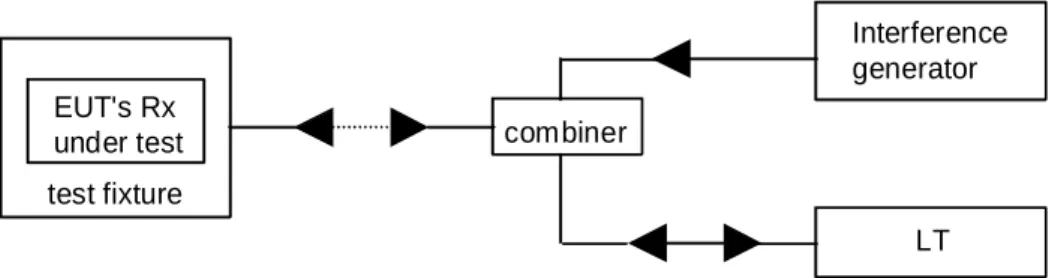
Figures 1 to 4 Void
Lower Tester
WRS Under Test
4.5.9.2
Testing as an RFP
A dummy bearer shall be generated by the Lower Tester or (if that is not possible) by an RFP supplied by the applicant and conforms to the present document. The WRS EUT shall be synchronized to the dummy bearer and shall operate as an RFP in test-stand-by Mode. The dummy bearer may change bearer during the test.
The EUT shall comply with the FT demands of the present document on reference timer accuracy, frequency accuracy, equipment identity and efficient use of the radio spectrum. See figure 6.
NOTE: The power combiner is not needed if the PP and RFP functions have different antenna connectors.
Lower Tester Power combiner Approved RFP or Lower Tester WRS Under Test Figure 6: WRS testing as an RFP
4.5.9.3 Additional
requirements
• The EUT shall provide a mechanism, see ETSI EN 300 700 [6] to control the number of multihops. • The EUT shall apply the defined, see ETSI EN 300 700 [6] frame multiplexing structure.
Additional requirements a REP version of WRS:
• The REP EUT shall conform to the requirements of ETSI EN 300 700 [6] for channel selection of double duplex bearers.
4.5.9.4 Conformance
Conformance tests as defined in clause 5.3.9 shall be carried out.
4.5.10 Requirements
for
PPs with direct PP to PP communication mode
4.5.10.0 General
requirements
Most PPs will be able to operate also in the normal non-direct communication mode. In this case the direct mode will be temporary, and all PPs in a group of PPs intended to communicate in direct communication mode have to be switched into this mode (manually or by other means), since a PP in non-direct mode can only receive paging information from the system to which it is locked. For further description see annex G of ETSI EN 300 175-3 [2].
PPs or CTAs in direct communication mode shall meet the PP requirements for normal non-direct communication with the amendments in clauses 4.5.10.1 to 4.5.10.4.
4.5.10.1
Setting the EUT in direct communications mode
Entering and leaving the direct communications mode shall be made by manual keypad entries or by other means. The EUT shall be set in direct communications mode provided with proper identities. If class E identities are used, the requirements for class E identities in ETSI EN 300 175-6 [4], clauses 5.5, 6.1.5 and 6.3.2 shall be met.
When not processing a call, the EUT shall be in active unlocked PP state.
4.5.10.2
When the EUT has not initiated a call
When the EUT has not initiated a call, it shall meet the "non-direct mode" PP requirements of the present document, but with the following amendments:
a) the EUT shall in the active unlocked PP state scan all channels on relevant carriers at least every T1 seconds; b) if ARI class E is used, the paged EUT is allowed to make the bearer setup attempt only on the channel pair
where the initiating PP transmits.
4.5.10.3
When the EUT initiates a call
By initiating a call means that the number of the wanted subscriber is entered via the keypad or by other means, and that the EUT at "off-hook command" shall enter the RFP active idle state. See ETSI EN 300 175-3 [2], clause 4.3.
When the EUT initiates a call, it shall meet the "non-direct mode" RFP requirements of the present document, but with the following amendments:
a) the 25 ppm PP timer stability requirements apply. See ETSI EN 300 175-2 [1] clause 4.2.2;
b) an EUT entering RFP mode is allowed to derive over the air frame and slot synchronization from a DECT system having "non-class E" identities;
c) the EUT shall use FP or PP simplex bearer channel selection rules for the RFP active idle state. See ETSI EN 300 175-3 [2], clause 11.4;
d) the page message shall be transmitted in every multiframe as long as in active idle state; e) the short page format shall be used for ARI class E;
f) the EUT shall revert from active idle RFP state to PP active unlocked state, if a duplex bearer has not been established within T2 > T1 seconds;
g) the PP is not required to do receiver scanning for ARI class E in RFP active idle nor active state. See ETSI EN 300 175-3 [2], clause 11.8 and ETSI EN 300 175-6 [4], clause 5.5;
h) if identities class E are used, the NT message will not contain an ETSI distributed code.
4.5.10.4 Conformance
Conformance tests as defined in clause 5.3.10 shall be carried out.
4.5.11 Distributed
Communications
4.5.11.0 General
requirements
PPs and CTAs with distributed communications option, HyPs, shall be tested as a stand alone PP and shall comply with all relevant PP test cases in the present document. In addition the HyPs shall be tested as an RFP as regards the carrier frequency demands of clause 4.5.1 and reference timer accuracy demands of clause 4.5.2.4.
The HyP EUT shall meet the requirements and the applicant's declarations as described below.
A HyP requires to be synchronized to a bearer to derive its reference timer for PT and FT transmissions.
4.5.11.1
Testing as a PP
The EUT shall operate as a PP in the test-stand-by mode, TSM, annex D, as a stand alone module. In this mode it shall be tested as a normal PP. See figure 7.