MGC-25/50/100
MGC+50/100
Release Notes
Version 9.0
August 2007
DOC2186A
All text and figures included in this publication are the exclusive property of Polycom, Inc. and may not be copied, reproduced or used in any way without the express written permission of Polycom, Inc. Information in this document is subject to change without notice. This document also contains registered trademarks and service marks that are owned by their respective companies or organizations.
If you have any comments or suggestions regarding this document, please send them via e-mail to [email protected].
Catalog No. DOC2186A Version 9.0
Notice
While reasonable effort was made to ensure that the information in this document was complete and accurate at the time of printing, Polycom, Inc. cannot assure the accuracy of such information. Changes and/or corrections to the information contained in this document may be incorporated into future issues.
Portions, aspects and/or features of this product are protected under United States Patent Law in accordance with the claims of United States Patent No: US 6,300,973; US 6,496,216; US 6,757,005; US 6,760,750; and US7,054,820.
Version 9.0 - New Features List... 1
Version 9.0 Upgrade Package Contents... 2
Prior to Installation and SW Upgrade ... 3
Hardware Update Notice ...3
Control Unit Update Notice ...4
Version 9.0 Interoperability Table ...4
Software Upgrade Procedure ... 7
Upgrade Checklist ...7
Removal of Redundant Configuration Files ...7
Dongle Upgrade ...8
Verifying the Dongle Serial Number ...8
MGC-50/MGC-100 ...9
MGC-25 ...9
Downloading the Dongle File ...10
Installing the Dongle File ...11
MGC Unit Software Upgrade Procedure ...12
Upgrading from a Version using Password for Entry Queue Routing ...12
Upgrading from a Version using Numeric ID for Entry Queue Routing ...13
Downloading the Software to the MCU ...13
MCU Disk Space Verification ...15
Installing the MGC Manager Software ...16
Manual Installation of the Default Message Services ...16
Updating the Entry Queue Services ...17
Version 9.0 Detailed Description - Video... 18
Automatic Setting of Cascading Link to CP 1x1 Layout ...18
Detailed Description ...18
Limitations ...19
Video Invite Additions ...20
Detailed Description ...20
Disconnecting Invited Participants ...21
Invite Mode Exit ...21
Version 9.0 Detailed Description - General ... 22
External DB Modifications ...22
Detailed Description ...22
Validation of the participant’s right to start a new conference with an external
database application ...22
Validation of the participant’s right to join an On Going Conference with an
external database application ...22
Permanent Conference ...24
Detailed Description ... 26
SilenceIT Additions ... 27
Detailed Description ... 27
Version 9.0 Detailed Description - Partners ... 30
Ad Hoc Conferencing in Avaya Environment ... 30
Detailed Description ... 30
Dial-plan and Dial-out Options for Microsoft’s Office Communicator ... 31
Detailed Description ... 31
Corrections, Pending Issues and Limitations... 33
Corrections between Versions V.8.0 and V.9.0 ... 33
Corrections between Versions V.7.5.0 and V.8.0 ... 37
Version 9.0 Pending Issues ... 40
Version 9.0 - New Features List
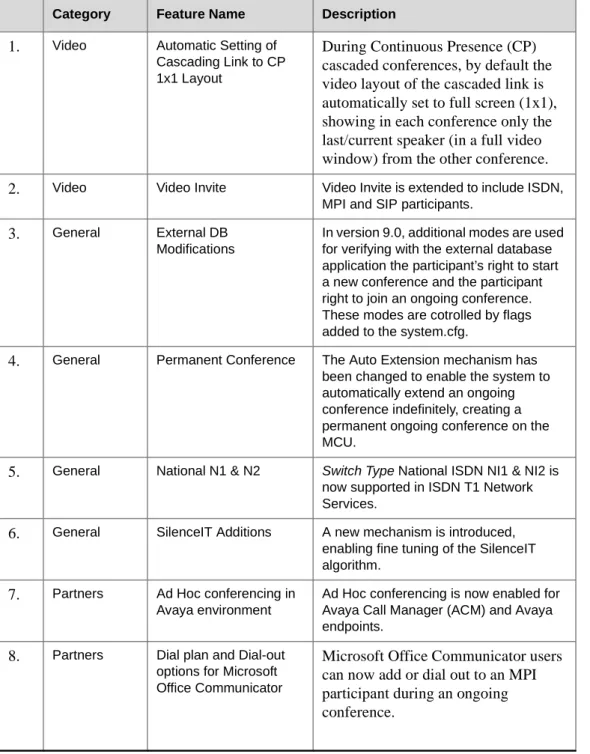
The following table lists the new features in Version 9.0.
Table 1: New Features List
Category Feature Name Description
1.
Video Automatic Setting ofCascading Link to CP 1x1 Layout
During Continuous Presence (CP)
cascaded conferences, by default the
video layout of the cascaded link is
automatically set to full screen (1x1),
showing in each conference only the
last/current speaker (in a full video
window) from the other conference.
2.
Video Video Invite Video Invite is extended to include ISDN,MPI and SIP participants.
3.
General External DBModifications
In version 9.0, additional modes are used for verifying with the external database application the participant’s right to start a new conference and the participant right to join an ongoing conference. These modes are cotrolled by flags added to the system.cfg.
4.
General Permanent Conference The Auto Extension mechanism has been changed to enable the system to automatically extend an ongoing conference indefinitely, creating a permanent ongoing conference on the MCU.5.
General National N1 & N2 Switch Type National ISDN NI1 & NI2 is now supported in ISDN T1 Network Services.6.
General SilenceIT Additions A new mechanism is introduced, enabling fine tuning of the SilenceIT algorithm.7.
Partners Ad Hoc conferencing in Avaya environmentAd Hoc conferencing is now enabled for Avaya Call Manager (ACM) and Avaya endpoints.
8.
Partners Dial plan and Dial-out options for Microsoft Office CommunicatorMicrosoft Office Communicator users
can now add or dial out to an MPI
participant during an ongoing
conference.
Version 9.0 Upgrade Package Contents
Version 9.0 upgrade package includes the following items:
•MGC Software CD
—
MGC Manager software
—MGC unit software
—External DB Tools
•
Documentation describing how to work with an external database application
for Ad Hoc Conferencing and Conference Access Authentication
•
Sample Scripts for working with an external database application
—
IVR
•
Default Message Services in English
•Message Services in Spanish
•Voice Messages in *.aca format
—File: system.cfg
•
MGC Documentation CD
—Version 9.0 Release Notes
—
MGC Manager User’s Guide, Volume I
—MGC Manager User’s Guide, Volume II
—MGC Manager User’s Guide, VoicePlus Edition
—MGC Administrator’s Guide
—
MGC-50/MGC-100 Getting Started Guide
—MGC+50/MGC+100 Getting Started Guide
—MGC-25 Getting Started Guide
—
MGC-50/MGC-100 Hardware and Installation Guide
—MGC+50/MGC+100 Hardware and Installation Guide
Prior to Installation and SW Upgrade
Reservations are automatically restored after software upgrade and you therefore do not
need to
Restore
reservations. However, it is recommended that you backup reservations
before and after upgrade using the Reservations Backup utility. Reservation backups may
not be compatible between versions.
Hardware Update Notice
Please make sure the hardware listed below is used with the listed MGC version and MGC
Manager versions:
Downgrading to lower versions is not supported by some of the new cards. Some of the
new features are only supported on the new hardware. Please consult with
Table 2
,
"MGC
Hardware" before downloading.
Table 2: MGC Hardware
# Board Type H/W
Version MGC Versions SIP H.264 H.239 AES MGC-50/MGC+50/MGC-100/MGC+100
1.
Audio+12/24 V1.04-7& V1.23
V5.17, V6.03 and later
n/a n/a n/a n/a
2.
Audio+24/48 V1.04-7,& V1.23
V5.17, V6.03 and later
n/a n/a n/a n/a
3.
Audio+48/96 V1.04-7,& V1.23
V5.17, V6.03 and later
n/a n/a n/a n/a
4.
Video+8 V2.03 V5.17,V6.03 and later
n/a n/a n/a n/a
5.
IP+12 V4.43 V6.03 and later YES YES YES YES6.
IP+24 V4.43 V6.03 and later YES YES YES YES7.
IP+48 V4.43 V6.03 and later YES YES YES YES8.
MUX+10 V4.42 V7.0 and later n/a n/a n/a YES9.
MUX+20 V4.42 V7.0 and later n/a n/a n/a YES10.
MUX+40 V4.42 V7.0 and later n/a n/a n/a YESMGC-25
11.
IPN V1.41 V6.11, V7.0 andlater
YES YES YES YES
12.
AUDIO-A V1.21 V6.11, V7.0.1and later
YES YES YES YES
Please be aware that upgrading the MGC-100 hardware may require upgrading the power
supplies and even the MGC chassis. Before upgrading the MGC-100, ensure that the power
consumption does not exceed the PS rating, and that the fuse rating is not exceeded when
using 110V AC supply. As a general guideline:
•
Old chassis (shipped with 300 W PS units) has a 10 amp fuse, while the new chassis
(shipped with 450 W PS units) has 15 amps circuit breaker
•
Each board consumes up to 40W apart from video boards.
•
The Video+8 board consumes 75W, and the Video6 board (older video board)
consumes 55W.
•
The Control Unit consumes 30W.
•
Each older power supply unit (marked as PWR on its front panel) provides 300W (AC
& DC).
•
Each new power supply unit (marked as POWER on its front panel) provides 450W
(AC & DC).
•
The new 450W AC PS fits into an old AC chassis, but it is not recommended.
•The new 450W DC PS does not fit into an old DC chassis.
Control Unit Update Notice
The MCU Control unit must have at least 128 MB of memory to run MCU Version 9.0 and
later.
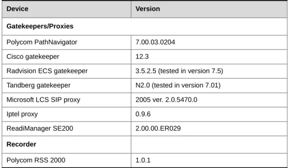
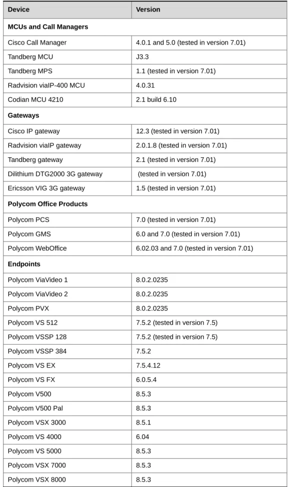
Version 9.0 Interoperability Table
The following table lists the devices with which Version 9.0 was tested.
Table 3: Version 9.0 Interoperability List
Device Version
Gatekeepers/Proxies
Polycom PathNavigator 7.00.03.0204
Cisco gatekeeper 12.3
Radvision ECS gatekeeper 3.5.2.5 (tested in version 7.5) Tandberg gatekeeper N2.0 (tested in version 7.01) Microsoft LCS SIP proxy 2005 ver. 2.0.5470.0
Iptel proxy 0.9.6
ReadiManager SE200 2.00.00.ER029
Recorder
MCUs and Call Managers
Cisco Call Manager 4.0.1 and 5.0 (tested in version 7.01)
Tandberg MCU J3.3
Tandberg MPS 1.1 (tested in version 7.01)
Radvision viaIP-400 MCU 4.0.31
Codian MCU 4210 2.1 build 6.10
Gateways
Cisco IP gateway 12.3 (tested in version 7.01)
Radvision viaIP gateway 2.0.1.8 (tested in version 7.01)
Tandberg gateway 2.1 (tested in version 7.01)
Dilithium DTG2000 3G gateway (tested in version 7.01) Ericsson VIG 3G gateway 1.5 (tested in version 7.01)
Polycom Office Products
Polycom PCS 7.0 (tested in version 7.01)
Polycom GMS 6.0 and 7.0 (tested in version 7.01)
Polycom WebOffice 6.02.03 and 7.0 (tested in version 7.01)
Endpoints
Polycom ViaVideo 1 8.0.2.0235
Polycom ViaVideo 2 8.0.2.0235
Polycom PVX 8.0.2.0235
Polycom VS 512 7.5.2 (tested in version 7.5)
Polycom VSSP 128 7.5.2 (tested in version 7.5)
Polycom VSSP 384 7.5.2
Polycom VS EX 7.5.4.12
Polycom VS FX 6.0.5.4
Polycom V500 8.5.3
Polycom V500 Pal 8.5.3
Polycom VSX 3000 8.5.1
Polycom VS 4000 6.04
Polycom VS 5000 8.5.3
Polycom VSX 7000 8.5.3
Polycom VSX 8000 8.5.3
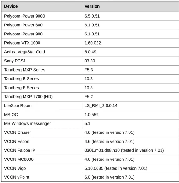
Table 3: Version 9.0 Interoperability List (Continued)
Polycom iPower 9000 6.5.0.51
Polycom iPower 600 6.1.0.51
Polycom iPower 900 6.1.0.51
Polycom VTX 1000 1.60.022
Aethra VegaStar Gold 6.0.49
Sony PCS1 03.30
Tandberg MXP Series F5.3
Tandberg B Series 10.3
Tandberg E Series 10.3
Tandberg MXP 1700 (HD) F5.2
LifeSize Room LS_RMI_2.6.0.14
MS OC 1.0.559
MS Windows messenger 5.1
VCON Cruiser 4.6 (tested in version 7.01)
VCON Escort 4.6 (tested in version 7.01)
VCON Falcon IP 0301.m01.d08.h10 (tested in version 7.01)
VCON MC8000 4.6 (tested in version 7.01)
VCON Vigo 5.10.0085 (tested in version 7.01)
VCON vPoint 6.0 (tested in version 7.01)
Table 3: Version 9.0 Interoperability List (Continued)
Software Upgrade Procedure
Upgrade Checklist
Prior to upgrading to Version 9.0 it is recommended you perform the following steps:
1.
Backup configuration and Reservations. For details, see the
MGC Administrator’s
Guide, Chapter 5
.
2.
Removing redundant configuration files. For details, see
“Removal of Redundant
Configuration Files”
on this page.
3.
The system saves the network cards’ circuit ID assignment during the upgrade process.
However it is recommended that you document the network cards’ circuit ID
assignments and order as displayed in the Card Properties.
4.
Version 9.0 requires the installation of a hardware key (dongle) on the MCU. For
details, see
“Dongle Upgrade” on page 8
.
5.
Install the new MCU version. Although the system automatically checks for free disk
space, if you prefer to manually check for free disk space before you download MCU
software, refer to
“MCU Disk Space Verification” on page 15
. For details about
installing the MCU software, see
“Downloading the Software to the MCU” on
page 13
.
6.
Install the new system.cfg file. For details, see
MGC Administrator’s Guide,
Chapter 5, Send File section
.
7.
Install the new MGC Manager version. For details, see
“Installing the MGC Manager
Software” on page 16
.
8.
Back up the configuration (
Backup Configuration
) and database files (
Backup
Reservations
) to create backups.
Removal of Redundant Configuration Files
In order to ensure smooth upgrades for MGC version, Reservations, Meeting Rooms and
Card configurations for an MGC that underwent a downgrade, it might be necessary to
manually remove specific configuration files. Please contact Polycom Support for further
instructions.
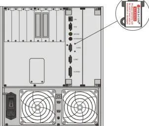
Dongle Upgrade
The MGC-50/100 is shipped with a dongle installed on COM1 of the rear panel. The
MGC-25 is shipped with a dongle installed on parallel port of the rear panel. If you are
upgrading from a version that did not require a dongle, contact Polycom support for a new
dongle.
When upgrading the MGC Manager version, you are required to upgrade your Dongle. If
you have a dongle, a new dongle file must be loaded to the MCU. To acquire the new
dongle file, access the Polycom Resource Center (see “Downloading the Dongle File” on
page 10) or contact your next level of support.
To verify if you have a dongle, you are required to inspect the rear panel of the MCU as
shown in Figure 1.
Figure 1: MCU-100 & MCU-25 rear panels and their dongles
Figure 2: MCU+ 50 rear panel and Dongle location
Verifying the Dongle Serial Number
The dongle label also includes the dongle serial number.
The dongle serial number can be found on the dongle label or by checking the Dongle
Information/System Configuration in the MGC Manager.
ALARMS COM2 COM1 KEYBOARD MOUSE VGA LAN P O L YCO M R WA R N IN G P rod uc t w a rr a n ty w ill be v o id if s e a l la be l is re mo ved o r d a mag e d .
MGC-50/MGC-100
•
To check the dongle serial number, right-click the MCU icon, and then click
Dongle
Information
.
The
Dongle Information
dialog box opens, displaying the dongle's serial number and
the current MCU version.
MGC-25
•
To check the dongle serial number, right-click the
MCU
icon, and then click
System
Configuration
.
Downloading the Dongle File
Prior to accessing the Polycom Resource Center Web site, retrieve the system serial number
from the MCU.
•
The MCU-25/50/100 have a Polycom label with a Serial No. fixed on the rear panel.
•On the Dongle, a white label either on the face or the side lists the Serial No.
To retrieve the Dongle File from a Polycom Web Site:
1.
Access the Polycom Resource Center web site http://extranet.polycom.com/csnprod/
signon.html.
2.
Enter your
User ID
and
Password
and click
Sign In
.
The
Welcome to the Polycom Resource Center
window appears.
3.
Click
MGC
Product Activation
.
The
MGC Dongle Upgrade File
window opens.
4.
In the
System Serial Number
field, enter the MCU number as listed on the MCU.
5.
In the
Dongle Serial Number
field, enter the serial number.
6.
Click
Download
.
Save the new dongle file.
The serial number displayed in the
Dongle Information
dialog box should match the
serial number of dongle as it appears in the name of the file sent to you (usually via
User ID and Password are required to access this site. If you do not have a User ID or Password, please refer to your next level of support. Due to a change in policy, your UserID is now your email address. You are required to request a temporary password.
e-mail). If the numbers do not match, do not proceed with the upgrade process and
contact support.
7.
Click
OK
when
Download
is complete.
Installing the Dongle File
To Upgrade the Dongle:
1.
Connect to the MCU.
2.
Right-click the
MCU
icon, click
MCU Utils
, and then click
Send Configuration File
.
The
Open
dialog box opens.
3.
Select the file
<nnnn>.don
from its location on your PC’s hard disk, and then click
Open
.
The dongle is being upgraded.
4.
Reset the MCU.
5.
Connect to the MCU and verify that the dongle information was updated; right-click
the MCU icon, and then click
Dongle Information
.
The new version number should be listed in the
MCU Version
box.
When the following error message appears: “No Maintenance Agreement Found/ MGC Serial Number not Found”, please contact your next level of support.
MGC Unit Software Upgrade Procedure
Upgrading from a Version using Password for Entry Queue Routing
Version 9.0 uses Numeric ID as the routing method from Entry Queues to destination
conferences. If your current version uses conference or chairperson password for routing
from Entry Queues to destination conferences, when upgrading to Version 9.0, you must
modify the system.cfg file included in the software kit.
To upgrade the MCU version:
1.
Download the MCU software to the MCU. For more details, see “MGC Unit Software
Upgrade Procedure”.
2.
To route participants from the Entry Queue to the destination conference using the
conference or chairperson password, you must modify the system.cfg file included in
the software kit:
a.
Open the system.cfg file located in the MCU software folder.
b.
In the GREET AND GUIDE/IVR section, change the value of
QUICK_LOG_IN_VIA_ENTRY_QUEUE flag to YES.
c.
Optional.
To assign the same Numeric ID to different non concurrent
conferences, in the GENERAL section change the value of
RESERVATION_CONFERENCE_ID_UNIQUE to NO.
d.
Save the file.
3.
Send the “system.cfg” file to the MCU (
MCU Utils -> Send File
).
4.
Reset the MCU.
5.
Install the MGC Manager application Version 9.0.
6.
In the MGC Manager application, list the IVR/Entry Queue Message Services.
7.
For each listed Entry Queue Service, assign the appropriate voice messages in the new
Conference ID tab.
Before upgrading the MCU software version:
• A new dongle file must be loaded to the MCU to upgrade from a previous version to version 9.X.
• Backup your configuration, including all Message Services.
• It is important to back up all reservations in the MCU. This is to safeguard against reservations being lost.
Upgrading from a Version using Numeric ID for Entry Queue Routing
Version 9.0 uses Numeric ID as the routing method from Entry Queues to destination
conferences. If your current version uses Numeric ID for routing from Entry Queues to
destination conferences (version 6.x and higher), no change in the system.cfg file is
required.
To upgrade the MCU version:
1.
Download the MCU software to the MCU. For more details, see “Downloading the
Software to the MCU”.
2.
Send the “system.cfg” file included in the software kit to the MCU (
MCU Utils ->
Send File
).
3.
Reset the MCU.
Downloading the Software to the MCU
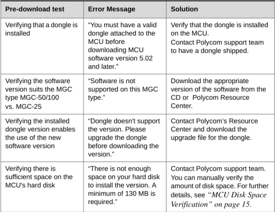
A pre-download check is performed to ensure a successful software installation.
The check is part of the MCU software download procedure. If no problem is detected, the
installation procedure is completed.
If the pre-download check detects a problem, the installation process is halted and the
following error messages are displayed with suggested solutions:
To ensure a successful pre-download check, please upgrade the MGC Manager before you upgrade the MCU.
Table 4: Software Pre-download Checks
Pre-download test Error Message Solution
Verifying that a dongle is installed
“You must have a valid dongle attached to the MCU before
downloading MCU software version 5.02 and later.”
Verify that the dongle is installed on the MCU.
Contact Polycom support team to have a dongle shipped.
Verifying the software version suits the MGC type MGC-50/100 vs. MGC-25
“Software is not supported on this MGC type.”
Download the appropriate version of the software from the CD or Polycom Resource Center.
Verifying the installed dongle version enables the use of the new software version
“Dongle doesn't support the version. Please upgrade the dongle before downloading the version.”
Contact Polycom’s Resource Center and download the upgrade file for the dongle.
Verifying there is sufficient space on the MCU's hard disk
“There is not enough space on your hard disk to install the version. A minimum of 130 MB is required.”
Contact Polycom support team. You can manually verify the amount of disk space. For further details, see
“MCU Disk Space
Verification” on page 15
.To install a software update on the MCU:
1.
On the
File
menu, click
Download MCU Software
.
Alternatively, right-click the
MCU
icon, click
MCU Utils
, and then click
Download
MCU Software
.
The
Logon
dialog box opens.
The
Login Name
and
Password
of the currently logged in operator are entered by
default. If required, enter another login name and password.
2.
Click
OK
.
The
Software Installation
dialog box opens.
The MCU software will be installed on each listed MCU.
3.
Select the
Install Default Services
check box to download the default IVR Service,
Entry Queue Service, and Gateway Service. The default IVR Service is in English and
is named
IVR90
. The default Entry Queue Service is in English and is named
EQ90
.
You can manually install the default English IVR Service and Entry Queue Service or
the English and Spanish IVR and Entry Queue Services. For more information, see
“Installing the MGC Manager Software” on page 16
.
4.
You can download software to all MCUs listed in the
MCU
List
in one operation. If the
list is not complete, you can add MCUs to the list by clicking the
Add MCU
button.
To avoid downloading the software to an MCU, remove the MCU from the list by
selecting the MCU Name, and then clicking the
Remove MCU
button. For more
details, see the
MGC Administrator’s Guide, Chapter 2
.
5.
In the
Enter path to source files
box, type the full path to the folder containing the
software version. Alternatively, click the
Browse
button and use standard Windows
techniques to select the
Folder
containing the software. If the folder is named
Vaaa.bbb, where aaa is the MGC Manager version number, and bbb is the MCU
version number.
6.
Click
OK
.
The software version’s path is displayed in the
Enter path to source files
box.
You need to select the folder containing the latest version number, and not the sub-folder labeled Disk 1.
7.
Click the
Install
button to start the installation procedure.
8.
Install the new system.cfg file.
a.
Right-click the
MCU
icon, select
MCU Utils
and the click
Send File
.
The
Install File
dialog box opens.
b.
Click the
Browse
button to open the
Select Source File
dialog box and select the
system.cfg
file, and then click
Open
.
The name of the file appears in the
Install
field in the
Install File
dialog box.
c.
Click
Yes
to proceed with file downloading to the MCU's hard disk.
The
Done
dialog box opens.
d.
Click
OK
.
9.
Reset the MCU.
MCU Disk Space Verification
In Version 9.0, during MCU software downloading process, the system automatically
verifies the amount of disk space available before the installation begins. It is still possible
to manually verify the available disk space using the IP Terminal.
To verify the disk space on the MCU:
1.
Right-click the
MCU
icon, and then click
IP Terminal.
The
Donkey-COM
window opens.
2.
In the command line of the
Donkey-COM
window, type
disk_stat
and press Enter.
The system displays information about the MCU disk.
In case the number of
Available Bytes
is lower than 130,000, please contact support
before installing the new version.
The default system.cfg file is located in the appropriate MGC SW CD folder. To access a modified system.cfg file, contact Polycom Support.
Installing the MGC Manager Software
The MGC Manager software is Windows 95/98/NT/ME/2000/XP based software.
After downloading the software from the FTP and unzipping the files:
1.
Open Windows Explorer and open the folder that contains the MGC Manager
diskettes.
2.
Browse to
Disk 1
and double-click the
Setup.exe
file.
3.
Follow the on-screen instructions to complete the installation procedure.
Manual Installation of the Default Message Services
When upgrading from versions 5.x, 6.0 and 6.0x directly to Version 9.0, the upgrade kit
includes new Message Services that can be automatically installed on the MCU during the
software installation. You can also manually install the default Message Services at the end
of the installation process.
The software CD contains two types of IVR Services:
•English
•
English and Spanish
The Automatic installation of Message services during MCU software update
automatically installs the English only Message Services. The manual installation
process enables you to install the English and Spanish Message Services as well as the
English only. When you install the English and Spanish IVR Service, two separate IVR
Services are created on the MCU and the English IVR Service is automatically set as
the default IVR Service.
To restore the Default IVR Service:
The default Message Services are installed using the
Restore Configuration
utility.
1.
Right-click the
MCU
icon, click
MCU Utils
, and then click
Restore Configuration
.
2.
Enter the path to the folder containing the configuration files to be installed, or click
the
Browse
button to locate them.
3.
From the Version 9.0 software folder, select the
English V9 IVR
or the
English and
Spanish V9 IVR
folder, according to the required Message Service, and click
OK
.
The system returns to the
Restore
dialog box.
4.
Click
OK
to continue.
5.
Click the
Select All
button.
6.
Click
OK
to install the default Message Services on the MCU.
7.
At the end of the Restore process, a message is displayed indicating that the MCU
must be reset to be able to use the new Message Services.
Updating the Entry Queue Services
When upgrading from Version 5.x directly to Version 9.0 you need to update the Entry
Queue Service to include the appropriate voice messages.
To update the Entry Queue Service:
1.
Expand the
IVR Message Services
list (under the MCU Configuration list).
2.
Right-click the icon of
Entry Queue Service
to update (an Entry Queue Service that
was defined in version 5.x), and then click
Properties
.
The
Entry Queue Message Service - General
dialog box opens.
3.
Click the
Conference ID/Password
tab.
4.
In the
Entry Queue Message Service - Conference ID/Password
dialog box, assign the
following voice messages:
—
Using Conference Password for Entry Queue Routing (Version 5.x mode):
•Request Conference ID/Password:
CONFPASS.
ACA•
Join Failure Message:
CONFRTRY.
ACAThese files are located in the MGC software kit (as part of the default IVR Service
for Version 9.0), in the following path:
MGC50-100 Version 9.0\MGC SW CD Ver 9.0\IVR\Default Services\English V9
IVR\msg\LANG90\NID\NUMID.
—
Using Conference Numeric ID for Entry Queue Routing:
•Request Conference ID/Password:
CNFIDRQS.
ACA•
Join Failure Message:
CNFIDFL.
ACAThese voice messages are located in the MGC software kit (as part of the default
IVR Service for Version 9.0).
Version 9.0 Detailed Description - Video
Automatic Setting of Cascading Link to CP 1x1 Layout
During Continuous Presence (CP) cascaded conferences, by default the video layout of the
cascaded link is automatically set to full screen (1x1), showing in each conference only the
last/current speaker (in a full video window) from the other conference.
Detailed Description
Previously, when cascading two CP conferences, the video layout displayed in one
cascaded conference inherited the video layout of the other conference in one of its
windows, resulting in a display of the other conference in very small squares.
Now, the cascaded link can be automatically set to Full Screen (1x1) in CP, automatically
forcing the speaker in the cascaded conference (B) to display in full window in the video
layout of conference (A).
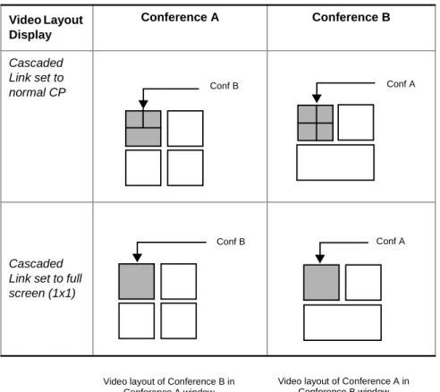
Figure 1-1 Video Layout Display in CP Cascaded Conferences
When an operator changes the layout in conference B, the CP 1x1 layout is cancelled and
the new layout (forced) is implemented.
Video Layout Display
Conference A Conference B
Cascaded Link set to normal CP
Cascaded Link set to full screen (1x1)
Conf B Conf A
Conf B Conf A
Video layout of Conference B in Conference A window
Video layout of Conference A in Conference B window
CP Full Screen (1x1) Layout setting of Cascading Link is supported in CP conferences for
H.323, SIP and ISDN links in the following modes:
•
Classic and Quad Views Video Sessions including Auto Layout setting
•Presentation Mode and Lecture Mode
Enabling the automatic CP 1x1 layout setting of the cascaded link:
•
Define the participant as a Casceded Link by setting the
Node Type
to
MCU
in the
Participants Properties - Advanced
dialog box.
•
In the Section PEOPLE PLUS CONTENT, set the system.cfg flag:
ENABLE_AUTO_1x1_LAYOUT_FOR_CASCADED_LINK
to
YES
.
•
When Auto Cascading functionality is enabled in the Entry Queue, the Profile and Ad
Hoc conference must have the same properties
Limitations
Cascaded Links are not supported in the following modes:
•Conferences set to the Same Layout mode
•
COP and Software CP conferences
•Connecting using MPI protocol
•
When a Gateway identifies itself as an MCU, endpoints behind the gateway connect in
a CP Cascade 1x1 layout. When the MCU functions as a gateway, the he system.cfg
flag - ENABLE_AUTO_1x1_LAYOUT_FOR_CASCADED_LINK must be set to
Video Invite Additions
In version 8.0, Video Invite was available to H.323 participants only. In version 9.0, Video
Invite is extended to include ISDN, MPI and SIP participants.
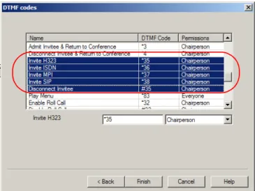
Detailed Description
By default, Invite options are automatically enabled in the IVR Service with the appropriate
DTMF codes. To invite H.323, ISDN, MPI and SIP participants to the conference, the
chairperson (or participant) dials
*35/*36/*37/*38
, and once the dial tone is heard, enter
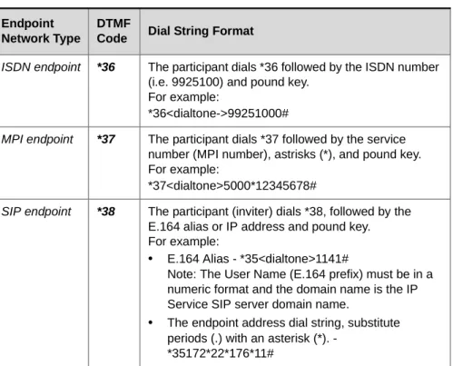
the dial string of the invitee’s endpoint as shown in Table 5, "Invite Dial String Format.".
With Invite, participants are connected using the appropriate default IP, ISDN and MPI
Network Service.
The DTMF codes can be modified, or deleted if you want to disable the Video Invite
feature.
• To invite Audio Only PSTN participants, use the Audio Invite DTMF options (*4).
• The simplified Ad Hoc Conferencing option introduced in version 8.0 can also be used to invite ISDN, MPI and SIP participants. For more details, see the MGC Manager User’s Guide Volume I, Chapter 6, Setting the Video Invite Options in the IVR Service.
Table 5: Invite Dial String Format Endpoint
Network Type
DTMF
Code Dial String Format H.323
endpoint
*35 The participant (inviter) dials *35, followed by the E.164 alias (i.e. 1141) or IP address and a pound key. For example:
• Using the E.164 Alias - *35<dialtone>1141#
Note: The invitee endpoint must be configured with an E.164 alias, and this alias must be registered to the same gatekeeper as the MCU.
• The endpoint’s IP address (172.22.176.11) dial string, substituts the periods (.) with asterisk’s (*) - *35<dialtone>172*22*176*11#
Note: Endpoint registration with the gatekeeper is not required.
Video Invite can be used in Video Conferences to which an Invite-enabled IVR Service is
assigned. Video Invite is enabled for the conference in the
Properties -Settings
dialog box
as for Audio Only and H.323 participants.
Disconnecting Invited Participants
To disconnect the last invited video participant (and not the last dial in participant), enter
the DTMF code
#35
, for all invitee types. Each time you enter #35, the system disconnects
the most recent invited participant.
Invite Mode Exit
The system automatically exists the video invite mode and returns the inviter to the
ongoing conference when :
•
A dial tone is heard, but no DTMF code is pressed within 5 seconds
•
When a DTMF code is activated but no number is entered within 10 seconds
•The pound (#) key is pressed directly after the DTMF code (i.e. *36#)
•
A wrong number is dialed or the pound (#) key is not pressed at the end of the dialed
number
•
No MCU recources. In such a case an error tone is heard.
ISDN endpoint *36 The participant dials *36 followed by the ISDN number (i.e. 9925100) and pound key.
For example:
*36<dialtone->99251000#
MPI endpoint *37 The participant dials *37 followed by the service number (MPI number), astrisks (*), and pound key. For example:
*37<dialtone>5000*12345678#
SIP endpoint *38 The participant (inviter) dials *38, followed by the E.164 alias or IP address and pound key. For example:
• E.164 Alias - *35<dialtone>1141#
Note: The User Name (E.164 prefix) must be in a numeric format and the domain name is the IP Service SIP server domain name.
• The endpoint address dial string, substitute periods (.) with an asterisk (*). -
*35172*22*176*11#
Table 5: Invite Dial String Format Endpoint
Network Type
DTMF
Version 9.0 Detailed Description - General
External DB Modifications
In version 9.0, additional modes are used for verifying with the external database
application the participant’s right to start a new conference and the participant right to join
an ongoing conference. These modes are cotrolled by flags added to the system.cfg.
Detailed Description
Validation of the participant’s right to start a new conference with an external database application
In previous versions, when the MCU was configured to verify the participant’s right to start
a new conference based on the conference ID, the system always queried the external
database application without first checking if a conference with that ID is already running.
In Version 9.0, you select whether the MCU sends the validation query to the external
database application without checking if the conference is already running, or only after
checking if the conference is already running. The system behavior is controlled by a
system.cfg flag.
To set the system validation mode for starting a new conference:
By default, the system is configured to maintain the current behavior and validate the
participant’s right to start a new on going conference without checking if the conference is
already running (flag is set to
NO
).
To modify the system behavior and validate the participant’s right to start a new on going
conference only after checking if the conference is already running:
•
In the system.cfg, in the GREET AND GUIDE/IVR section, manually add the flag
AD_HOC_EQ_DIRECT_ONGOING_CONF=YES.
Validation of the participant’s right to join an On Going Conference with an external database application
In previous versions, participant’s right to join a conference with an external database was
authenticated using a password or PIN code.
In version 9, the authentication can also be done using the participant’s CLI (Caller ID). In
such a case, the system does not prompt for conference password and the query to the
external database application is automatically sent using the participant’s CLI. The
authentication mode is controlled by a system.cfg flag.
To set the authentication mode for joining an on going conference:
By default, the system is configured to maintain the current behavior and use a Password or
PIN code for authentication with the external database application (flag is set to
NO
).
To modify the system behavior and enable CLI authentication with the external database
application:
• Ad Hoc conferences require the use of an Audio+ board, combined with the Entry Queue and IVR
• Ad Hoc conferences are initiated via an Entry Queue. SIP endpoints can initiate Ad Hoc conferences using SIP Factories.
•
In the system.cfg, in the GREET AND GUIDE/IVR section, manually add the flag
USE_CLI_AS_PWD_FOR_EXT_DB=YES
When the participant connects to a conference, the MCU uses the participant’s CLI to
query the external database application.
When the flag is set to YES, the system does not prompt for password and the request to the external database application includes a dummy password (999886) which is ignored by the external database application during authentication.
Permanent Conference
The Auto Extension mechanism has been changed to enable the system to automatically
extend an ongoing conference indefinitely, creating a permanent ongoing conference on the
MCU.
Detailed Description
The automatic extension of the conference indefinitely is enabled by activating the Auto
Extension mechanism and setting the conference duration to 99.59, making sure that it is
the duration when the conference becomes ongoing.
Changing the duration once the conference is started will not change its permanent status.
In the AUTO_EXTENSION section of the
confer.cfg
file the flag
EXTENSION_TIME_INTERVAL=30 determines the number of minutes by which the
conference is extended during a conference. For example, if you enter 30 (default), the
conference is automatically extended by 30 minutes each time the system verifies whether
to extend the conference.
The Auto Extension flag MAX_EXTENSION_TIME is ignored when the conference
duration is set to 99.59, and the conference can be extended indefinitely.
When the MCU is reset, the conference is restarted on the MCU but it is not permanent as
the duration changes to the actual time left as calculated by the MCU. In such a case, a new
permanent conference must be created.
• Each time the conference is extended, an event is added to the CDR file, until the file size reaches 1 MB. Once this limit is reached, no additional events are added to the CDR but they are written to the log file. When the conference ends, the appropriate event is added to the CDR file.
• When checking the properties on the ongoing permanent conference after the first extension, the dialog box should be closed using the Cancel button and not the OK button.
• Once the conference is extended beyond the initial 99.59 hours, incorrect duration is displayed in the conference properties, and the value switches between 99.59 and 99.29.
National ISDN NI1 & NI2
Switch Type
National ISDN NI1 & NI2 is now supported in ISDN T1 Network Services.
This option is available for ISDN T1 in North America.
Detailed Description
In the
ISDN Network Service - Span
Definition
dialog box, in the
Switch Type
list, select
SilenceIT Additions
A new mechanism is introduced, enabling fine tuning of the SilenceIT algorithm.
Detailed Description
In previous versions, in some cases, the SilenceIT algorithm was not sensitive enough to
the noise level causing speech to be muted, or not muting music and noise.
In version 9.0, the new mechanism enables the system to measure the audio energy, and
based on this measurement, fine-tune the system usage of the SilenceIT algorithm. To
reliably measure the audio energy and apply the new mechanism, speech and noise/music
must have sufficient energy, and be consistent across all audio ports.
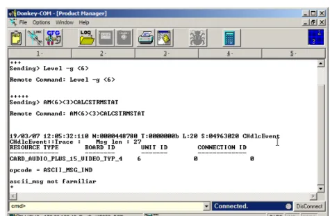
The audio energy measurements are done by connecting an endpoint to an ongoing
conference, and using the IP Terminal to detect the noise/speech level. The values
measured are then compared to the values listed in Table 6 on page 1-28. Based on the
range of these values the user locates the corresponding parameter which is used to
configure a system.cfg flag.
To enable the SilenceIT algorithm and fine-tune its operation:
1.
Create an ongoing conference and connect an endpoint using a noisy line.
2.
In the
Cards
section, locate the audio card used to handle the participant connection to
the conference and write down the slot and unit numbers.
3.
Using the participant’s endpoint place the call on-hold.
When the participant places the call on-hold music is heard.
4.
Right-click the
MCU
icon, and then click
IP Terminal.
The
Donkey-COM
window opens.
5.
In the
cmd>
field enter the following command:
Level -g <slot #>
and then press
<Enter>.
6.
In the command line enter:
AM<slot#><unit #>CALCSTRMSTAT
and press
<Enter>.
The message
“Started gathering signal statistics”
appears, indicating that the data
gathering process has started.
8.
In the command line enter:
AM<slot#><unit #>GETCSTRMSTAT
and press
<Enter>.
The signal statistics are retrieved and are displayed in the
Donkey-COM
window. Look
for these parameters in the following format:
“Average Energy = <Energy> Total VADS = <Total Vads>Consecutive VADS = <
Consecutive Vads>”.
If many messages are displayed, wait two minutes, and repeat step 8.
9.
Record the
Energy, Total Vads
and
Consecutive Vads
values and locate these values in
Table 6 on page 1-28 according to the
Noise Environment
(whether the call was placed
from a quiet room or a noisy environment such as a cellular phone). Retrieve the
corresponding parameter value.
Table 6: Noisy Line Tuning Table
Energy Noise
Environment Total VADs
Consecutive VADs
Parameter Value
91<E<128 Or
182<E<256
Quiet V < 50 V < 50 1
76<E<91 Or
152<E<182
Quiet V < 50 V < 50 2
67<E<76 Or
134<E<152
Quiet V < 50 V < 50 3
0<E<67 Or
128<E<134
Quiet V < 50 V < 50 4
91<E<128 Or
182<E<256
10. By default, the SilenceIT mechanism is disabled. To enable it, right-click the
MCU
icon and then click
MCU Utils>Edit “system.cfg”
.
11. In the
AUDIO PLUS FLAGS
section, add the flag
NOISE_LINE_DETECTION
=
and enter the value found in step 9. Setting the flag value to 0 disables the SilenceIT
mechanism.
For more details about flag definition and system.cfg, see the
MGC Administrator’s
Guide, Chapter 5
.
12. Click
OK
.
13. Reset the MCU.
76<E<91 Or
152<E<182
Noisy V < 50 V < 50 6
67<E<76 Or
134<E<152
Noisy V < 50 V < 50 7
0<E<67 Or
128<E<134
Noisy V < 50 V < 50 8
E >1000 Variable 700<V 150<V<200 9 E >1000 Variable 650<V<700 150<V<200 10 E >1000 Variable 600<V<650 150<V<200 11 E >1000 Variable 500<V<600 150<V<200 12 E >1000 Variable 700<V 200<V<250 13 E >1000 Variable 650<V<700 200<V<250 14 E >1000 Variable 600<V<650 200<V<250 15 E >1000 Variable 500<V<600 200<V<250 16
E >1000 Variable 700<V 250<V 17
E >1000 Variable 650<V<700 250<V 18 E >1000 Variable 600<V<650 250<V 19 E >1000 Variable 500<V<600 250<V 20
Table 6: Noisy Line Tuning Table
Energy Noise
Environment Total VADs
Consecutive VADs
Parameter Value
Version 9.0 Detailed Description - Partners
Ad Hoc Conferencing in Avaya Environment
Ad Hoc conferencing is supported in Avaya environment.
Detailed Description
To enable Ad Hoc Conferencing for Avaya endpoints:
The administrator must configure the ACM and MGC for Ad Hoc conferencing.
In the MGC Manager, define one or several new Meeting Rooms. In the Avaya Call
Manager (ACM) application, define the video conferencing parameters using the the names
of the Meeting Rooms defined in the MGC Manager.
Once Avaya endpoints request to start a video conference, the Avaya Call Manager (ACM)
will initate a call to the one of the Meeting Rooms configured in its application.
Dial-plan and Dial-out Options for Microsoft’s Office
Communicator
A flexible dial-plan is available for MPI, ISDN, H.323 and SIP using Microsoft Office
Communicator. In addition, the use of a flexible number of digits for MPI, ISDN, H.323
and SIP dialout strings are enabled in the system.cfg.
Detailed Description
The MGC system supports the use of MPI calls, with MPI Network Service Dialing Mode
set to DIAL. In the
Call via Conferencing Service
of
Microsoft Office Communicator,
the
user can dial out to MPI endpoints using two methods:
•
Prefix and Number: for example, 5551234567, where 555 is the MPI Prefix as defined
in the system.cfg and 1234567 is the dial-in number.
•
Dial string; for example: [email protected];user=mpi.
• The user can use the same dialout methods for ISDN, SIP, H.323 or PSTN endpoints.
• For more information using the Call via Conferencing Service see, Microsoft-Polycom Integrated Deployment Guide Phase 5, Chapter 3 “Polycom Meeting Scenarios”, “An Office Communicator User Dials out to another Office Communicator User”.
New MPI Flag
In the system.cfg a new MPI flag SIP_REFER_MPI_PREFIX= <value> has been added to
the SIP_REFER_PREFIX_AND_PHONES section. The dialout example shown on the
previous page shows the prefix <value = 555> as it should be configured in the system.cfg.
Figure 2: Sample system.cfg file
To dial out to another Office Communicator using MPI:
1.
Start a new conference.
2.
Add a participant that is away or offline to the conference.
3.
In the Office Communicator Contacts list, right-click the contact to
call, click
Call via Conferencing Service
, and then click
Other
.
4.
Select either
New Address
or
New Phone Number
.
The system.cfg flag DIGITS_IN_PHONE_NUMBER=<VALUE> has been removed from the version.
Corrections, Pending Issues and Limitations
Corrections between Versions V.8.0 and V.9.0
Table 7: Corrections between Versions V.8.0 and V.9.0
#. Category Description ID# Remarks
1.
API A memory leak occurs on API server in the participant object, when updating the private layout.VNGM - 1780/ VNGFE -460
2.
Cascading Meeting Rooms running on different MGC 25 cannot be cascaded using IP links.VNGM - 1902/ VNGFE -572
3.
Cascading In H.243 cascading, the site name of an endpoint connected to a Slaveconference is displayed incorrectly.
VNGM-1621/ VNGFE -185
4.
General Conference password automatically allocated by the system is not random and always starts with 0, 1 or 2.VNGM - 1475/ VNGFE -341
5.
General The last letter in the site name of an ISDN endpoint connected via leased line is truncated when displayed on the other endpoint monitors.VNGM - 1729/ VNGFE -431
6.
General The "Release Hold" option is not functioning when selected from the toolbar or using the right click menu. Although the icon showed that the conference was no longer on hold, the on hold music continued playing and the conference couldn't begin.VNGM - 1776/ VNGFE -492
7.
General Truncated characters at the end of site names.VNGM - 1905/ VNGFE -579
8.
H.239 When a VSX endpoint connects or disconnects to/from a conference to which VSX and iPower endpoints are connected, it causes the iPower to stop sending Content and the iPower must be restarted.VNGM - 1491/ VNGFE -296
9.
HD An HD endpoint is connected as Secondary (audio only) when connecting to a VSW conference whose line rate is 1920Kbps and the video parameters are fixed (disabling the Highest Common mechanism).VNGM-1578
10.
HD Video freezes occur when a LifeSize Team endpoint version 2.1 changes its resolution from HD to QCIF.VNGM-1665
11.
HD Video artifacts are seen when an HDX endpoint version 1.0.1 connects to an HD Video Switching conference at a line rate of 1920Kbps and H.264 video.VNGM-1841
12.
HD When a non-HD endpoint connects toan HD Video Switching whose bit rate is higher than 1152Kbps and the video parameters are fixed (disabling the Highest Common mechanism), the HDX endpoint disconnects from the conference.
VNGM-1661/ VNGM-1594
13.
Interop LifeSize ISDN endpoint "Room ver2.1.3(5)" cannot connect to a CP-Classic conference via dial-in or dial-out.VNGM - 1440/ VNGFE -311
14.
Interop Tandberg endpoint version 5.2 is muted unexpectedly by the MCU during calls.VNGM - 1717/ VNGFE -330
15.
Interop LifeSize endpoint Room Ver 2.1.3(5) that does not support H.261 cannot connect to MGC.VNGM - 1718/ VNGFE -376
16.
Interop An exception occurs when a Tandberg endpoint version F6.0 defined as video dial-in connects to the conference as Audio only or when connected using video protocol H.264 with Profile 0 (invalid H.264 Profile).VNGM - 1917/ VNGFE -574
17.
Interop A Tandberg endpoint is connected as Secondary (audio only) when connecting to a VSW conference whose line rate is 1152Kbps and video parameters set to automatic mode with a connected HDX ISDN endpoint.VNGM-1685
18.
IP The IP48 card stops responding when dialing in to COP target conference via an Entry Queue.VNGM - 1725/ VNGFE -466
Table 7: Corrections between Versions V.8.0 and V.9.0
19.
IP Occasionally a stack controller failure occurs on the IP+48 while the card is used for conferencing.VNGM - 1883/ VNGFE -564
20.
IP MGC that is not registered to the gatekeeper cannot dial out to an H.323 participant that is registered to the gatekeeper in routed mode.VNGM - 1979/ VNGFE -648
21.
IP When the first IP card is busy, the call is not forwarded to the next available IP card on an MCUVNGM - 1989/ VNGFE -631
22.
IP+48 The IP+48 card stack controller crashes when running two P+C conferences on the same card.VNGM - 1720/ VNGFE -427
23.
IVR Participants entering the conference after the Chairperson has connected still hear the message "You Are the First To Join the Conference".VNGM - 1988/ VNGFE -649
24.
IVR The MGC does not recognize correctly H245 DTMF tones sent from Cisco Call Manager when they are dialled rapidly and in bursts.VNGM -1692/ 1700/ VNGFE -420
25.
MPI Content refresh rate is very slow when Content is sent from Aethra MPI endpoint.VNGM - 1785/ VNGFE -305
26.
MUX Occasionally when an ISDN endpoint disconnects from a Video Switching conference whose line rate is 384 Kbps and is set to H.264, G.722 (56), and includes both ISDN and MPI endpoints, the connection status of the endpoints still connected changes to “Faulty Connected”.VNGM-1623/ VNGFE -335
27.
MUX Occasionally when an ISDN VSX 7000endpoint connects to a COP conference set to Line Rate of 2B, Video Protocol H.261, and Audio Algorithm G.711 that also includes NEC VisualLinks TC5000-EX endpoints, the VSX 7000 connection status changes to “Faulty Connected”.
VNGM-1810/ VNGFE -361
28.
MUX, ISDN Occasionally VSX 3000 endpoints failed to connect to conferences using encryption.VNGM-1619/ VNGFE -369
Table 7: Corrections between Versions V.8.0 and V.9.0
29.
NET-8 card The Net-8 card active LED (yellow) remains lit after the conference ended and not card ports are used for conferencing. VNGM - 1778/ VNGFE -47930.
Personal SchedulerWhen updating the conference start time from the Personal Scheduler, the conference start time is not updated on the MCU. VNGM - 1399
31.
PSOS Operating SystemIn rare occasions, the MCU operating system (PSOS) loses connection with the dongle causing errors in all ongoing conferences, cards assert “NO CONNECTION WITH CARD” and system assert “DONGLE NOT ATTACHED”.
VNGM - 1842/ VNGFE -433
32.
SIP The MGC fails to find the required Entry Queue when the address received from a SIP dial in party includes a local dial plan string.VNGM - 1459
33.
SIP DTMF codes *76 and #76 (Increase/Decrease Listening Volume) are not activated for SIP endpoints.
VNGM - 1815/ VNGFE -544
34.
Video 0.5-1.0 second lipsync delay when using the Standard video card for conferencing.VNGM - 1728/ VNGFE -579
35.
XP Operating SystemWhen retrieving formatted CDR files from workstations running Windows XP SP2 and MGC manager 7.5.1 a Unicode error message is displayed "You cannot use unicode name".
VNGM - 1477/ VNGFE -331
Table 7: Corrections between Versions V.8.0 and V.9.0
Corrections between Versions V.7.5.0 and V.8.0
Table 8: Corrections between Versions V.7.5.0 and V.8.0
#. Category Description ID# Remarks
1.
API Compilation error occurs whencompiling 7.0 SDK with third party application.
20831
2.
API CDR retrieval generates two problems: • Memory leak• Corrupted CDR files cause the CDR application to describe all events in the CDR as Unrecognized Events.
21471
3.
Audio There are a lot of ipload.cpp asserts, taskapi.cpp asserts and audio noise during the conference starts.20877
4.
Audio+ Occasionally Audio disconnects, and Audio+ cards crash.20999 / 21466
5.
Auto Cascade In large auto cascaded conferences with a Master Meeting Room and 11 Slave Meeting Rooms, the IP+ card may crash.21221
6.
Cascade In an ISDN Master-Slave cascading conference, if participants are connected to the conference before connecting the links between the conferences, the site names disappear after the speaker changes.17373 Connect first the Cascading link.
7.
Cascade In an ISDN Master-Slave cascading conference, if participants are connected to the conference before connecting the links between the conferences, it takes about a minute for a Tandberg endpoint to become the speaker.17390
8.
Control Unit MCU LAN card causes intermittent disconnections. (Lan driver fix)21327
9.
Control Unit Previously, the MGC's XP Control unit used to accept loose source routed IP packets. Now the MGC drops all incoming Source Routed packets.VNGM - 1155
10.
CP Poor lip sync in low bitrate (128 and 256 Kbps) H.264 and H.263 CP conferences.22271
11.
General Participants moved between conferences may be listed in both conferences.12.
General The MCU occasionally disconnects from MGC manager when using a secured port (port 443 - SSL).20880 Reconnect to the MCU.
13.
General The 'Auto_Redial' parameters in 'confer.cfg' file are not updated.20897 Require MCU restart in order for changes to take effect.
14.
General Wrong memory allocation, after months of working in Reservation mode, results in video freezes and audio loss.21110
15.
General The MCU got gsegment.cpp, termsock.cpp asserts & MMGR exception.21589
16.
General When you create a Meeting Room with Entry Queue access and assign a Numeric ID, change the ID once and then change back to the original ID value, the following error message is generated: “Conference ID occupied”.21614
17.
General When running large conferences (120 participants) after 1.5 hours, the MGC Manager and API applications disconnect and the connection to the MCU is lost. The conferences continue running for about 20 min. and then the MCU self-reboots.21808
18.
General The MCU self-reboots with no activity on it, NVERCFG.CPP asserts appear.22097
19.
GW Connecting POTS to H.323 by theMGC Gateway fails in Version 7.x XPEK MGC
21916
20.
H.239 In an H.239, P+C conference, ISDN endpoints cannot reconnect after being disconnected. An error is displayed: “End init com not received”.21951
21.
IP The Stack Controller and RTPprocessors crash even when no conferences are running on MCUs with an IP24 card.
21456
22.
ISDN An H.320 participant connecting to a conference defined as Pro-Motion (NTSC) and line rate of 384 Kbps may connect as Secondary.10891 Disconnecting and reconnecting this participant can solve the problem.
Table 8: Corrections between Versions V.7.5.0 and V.8.0
23.
ISDN Sometimes ISDN endpoints fail to move from one Video Switching conference to another when the line rate of the destination conference is higher then the line rate at the initial conference.20932
24.
IVR In reserved conferences with enabled recordings that are configured to start immediately, the first participant in the conference continues to hear music even after others have joined.21253
25.
Lecture Mode In a VSW lecture, ISDN or IPconference, you can not force a lecturer from the MGC Manager conference properties.
20653
26.
Lecture Mode In an H.320 Only conference with Lecture Mode and Auto switching between participants enabled, the video of the Lecturer does not synchronize each time that new participants join.21543
27.
MGC Manager On an XPEK MCU, when extreme packet loss occurs, the MGC Manager can loose connection with the MCU.21519
28.
PVX During MCU dialout, the PVX endpoint connects as “Secondary” when the dial out call is set to H.263 and the endpoint VGA Encoding is enabled.21115
29.
VSW When you switch between endpoints in large Video Switching (86 participants) conferences with 128 kbps line rate using H264 video protocol, an assert error and poor connection between the MCU and the MGC Manager resulting in an auto reboot.21673
30.
Video The endpoint doesn't change mode from QCIF to CIF in H264.20857
31.
VTX1000 VTX1000s in wideband connections do not provide DTMF feedback tones.VNGM -998
Table 8: Corrections between Versions V.7.5.0 and V.8.0
Version 9.0 Pending Issues
Table 9: Pending Issues
#. Category Description ID# Remarks
1.
Audio When using the G.729 audio algorithm, no audio is available with VoIP or SIP phones.20554/ 19609
2.
Cascade In Cascaded Video Switching conferences with an ISDN link, FECC occasionally does not work.20299
3.
COP When the first active participant is disconnected and the video of other participants is muted, participants view background colors.19288
4.
CP MCU status changes to Major for 30 seconds when connecting 32 endpoints at a line rate of E1 to a CP conference.20331
5.
CP Fragmented video can occur duringspeaker changes in CP H.264 conferences.
21311
6.
Database In the Participants database, when you Copy As a participant template and modify this template without prior pasting the copied template, the system forces you to save the original template under a different name.21142 Save the participant under a new name, and then, if required, delete it from the database.
7.
Diagnostics Long loop test may fail when running the diagnostic on the MGC-2520467
8.
Diagnostics Diagnostics sometimes cannot connect to the cards.21551
9.
Encryption In a Video Switching encrypted conference with more than 75 participants and set to a 768KB line rate, the Audio+ card may crash.19552
10.
Encryption When more that two encrypted, H.263 IP endpoints (VSX and FX.3) using E1 (1920 Kbps) line rate connect to the same card RTP they may experience video artifacts.VNGM- 682
11.
Encryption In ISDN encrypted (AES) conference, when synchronization is lost, the endpoints close the encryption channel, stop responding to MCU requests and stop sending video.VNGM-1928