19
Disk Storage and Basic File Structure
Marios Hadjieleftheriou
AT&T Labs
Apostolos N. Papadopoulos
Aristotle University
Donghui Zhang
Northeastern University
19.1 Introduction. . . . 19-1 19.2 Storage Media. . . . 19-2
Primary Memory•Secondary Storage•Tertiary
Storage
19.3 The Hard Disk Drive. . . . 19-5
Design and Operation•Physical and Operational
Characteristics•Efficient Data Storage Organization 19.4 Files and Records. . . .19-12
Physical Representation of Records•Organizing
Records Into Pages•Organizing Pages Into Files
19.5 The Buffer Manager . . . .19-17
The Concept of Buffering•Replacement Policies•
Buffering Structured Pages
19.6 Disk Arrays. . . .19-20
Efficiency and Availability•RAID Levels•
Combinations of RAID Levels•Summary of RAID
Schemes
19.7 Storage Systems. . . .19-27 19.8 Conclusions . . . .19-29
19.1
Introduction
The glorious history of the Hard Disk Drive begins back in 1956 when IBM introduced RAMAC [LH57], a magnetic storage media with an enormous, for the time, total capacity of 5 megabytes. Fifty years since the first commercial drive, the disk drive is the prevailing storage media in almost every computer system to date. Surprisingly, despite the signifi-cant technological improvements in storage capacity and operational performance, modern disk drives are based on the same physical and electromagnetic properties that were first introduced by the RAMAC.
In this chapter we perform a gentle introduction to the most important properties of storage media in general and disk drives in particular, and the way information is organized internally in these storage devices. Data-oriented applications such as Database Manage-ment Systems (DBMSs) are based on the low-level organization of data to create more complex constructs, like files and database relations. Therefore, the low-level operational characteristics of storage devices play an important role on the design of complex data man-agement software and has a direct impact on performance. The importance of the low-level properties of storage media is compounded by the wide variety of storage media present in the memory hierarchy of a computer system that have diverse characteristics in terms of access speed and storage capacity.
0-8493-8597-0/01/$0.00+$1.50
c
Furthermore, we examine in more detail hard disk drives and the higher-level disk based organization of data that has been adopted by modern DBMSs into files, pages, and records. We look at a variety of data storage strategies that enable efficient handling of processing tasks that require data to be moved across the various levels of the memory hierarchy continuously, and are, hence, greatly affected by the access speed of hard drives that is orders of magnitude slower than main memory.
Despite the technological improvements achieved today in single-disk storage systems, the disk is still a serious performance bottleneck in I/O-dominated applications. An important direction towards alleviating this bottleneck is to exploit several disk drives concurrently, enabling parallelism when possible. Towards this goal, the disk array has been introduced, which uses multiple disk devices to store information. Since by increasing the number of disk devices, disk failures may occur at much higher rates, the disk array needs to be enhanced with appropriate mechanisms towards fault tolerance in order to increase data availability. We also discuss in detail various techniques for guaranteeing various levels of fault tolerance in disk arrays.
Finally, we present the three prevailing technologies for connecting hard disk drives and other secondary and tertiary storage devices to a computer system. In particular, we elab-orate on the differences between directly attaching storage devices to a computer system versus accessing information over the network using network attached storage.
The rest of the chapter is organized as follows. Section 19.2 briefly describes the char-acteristics of storage media and illustrates the memory hierarchy that modern computer systems use for processing information. Section 19.3 focuses on the hard disk drive and discusses its basic operational characteristics and properties. Data are organized by means of records and files. These issues are discussed in Section 19.4, whereas buffering is studied in Section 19.5. Next, we discuss efficiency and data availability issues and we give the most important properties of disk arrays in Section 19.6. Section 19.7 briefly illustrates the prevailing approaches of connecting storage devices to computer systems. Finally, Section 19.8 concludes the chapter.
19.2
Storage Media
With the introduction of the stored-program computer, first detailed by John Von Neu-mann in 1945, came the advent of modern general purpose computers. The Von NeuNeu-mann architecture, as it is commonly referred to, ties the central processing unit with a storage structure — the computer’s memory — that stores both data and program instructions, implementing, as a consequence, a computer that is a Universal Turing Machine. Hence, memory became an inseparable component of almost every computer system to date. Cur-rent state-of-the-art computers utilize a memory hierarchy consisting of various types of storage devices, each of which has characteristics that make it suitable for a wide range of applications.
Computer memory can be classified into various categories, according to its read/write capabilities, support for random or sequential access, volatility, capacity, access speed, cost per byte, portability, longevity, reliability, and many other facets. Memory is also classified according to its proximity to the central processing unit, more specifically into primary, secondary and tertiary storage.
Intuitively, for performance considerations, the closer the memory is to the CPU the faster the data access speed that needs to be supported. As data is stored further away from the processor, capacity rather then speed plays a more important role and, secondarily, cost and longevity. With today’s technology, faster and more reliable memories that are
Registers
Cache
Main Memory
Hard Disk Drive
Optical Disks (DVD-ROM, CD-ROM)
Tape Drives
Flash Memory
Primary
Secondary
Tertiary
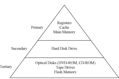
FIGURE 19.1: The memory hierarchy.
based on semiconductors are quite expensive to manufacture, hence their cost per byte tends to be high. On the other hand, slower electro-mechanical and optical storage devices offer significantly smaller cost per byte, much larger capacities, and permanent storage of information without the need for continuous power supply. For that reason, primary memory tends to be very small in size, and typically the closer the memory is to the CPU the smaller the size. On the other hand, secondary memory, being considerably cheaper, features sizes many orders of magnitude larger than primary memory, but with a significant impact on performance. The size of tertiary storage is virtually unlimited since it can always be extended with very small cost.
A typical memory hierarchy of a modern computer system is shown in Figure 19.1. Pri-mary memory consists of CPU registers, cache, and main memory which are all semicon-ductor based media. Secondary memory consists of magnetic disk drives. Tertiary memory, which is used for offline storage of information, consists of tape drives, optical devices (like DVD-ROMS) and flash memories. Database systems need to make efficient use of the mem-ory hierarchy in order to guarantee good performance. In order for the database system to operate on the data, the data needs to be placed either in cache or main memory. Straight-forwardly, since the size of a typical database is expected to exceed the capacity of available primary memory, transferring data between secondary and primary storage is unavoidable. For that reason, the design of database algorithms is heavily influenced by this bottleneck, trying to minimize the total cost of transferring data between various levels of the memory hierarchy. The following sections describe in more detail the major types of storage media in use today, as well as optimization strategies for efficient use of the memory hierarchy.
19.2.1
Primary Memory
At the top level of the memory hierarchy are the processor registers which provide the fastest possible read/write access to data (usually one CPU cycle) and have sizes of only up to a few bytes. Processor registers are used for storing and retrieving data that is being accessed directly by currently executing instructions.
Next is the processor cache which is a small and very fast read/write memory used for storing data that has been recently accessed from slower storage devices. The cache memory is further layered into two (and occasionally three) levels, once more for balancing
the fundamental trade-off between latency and cost. Level 1 cache (L1) is build into the processor core and thus can be accessed in just a few CPU cycles. Typical sizes are in the range of tens of kilobytes. For example, the AMD Athlon 64 FX processor has a total of 128 kilobytes L1 cache per core, 64 kilobytes for data and 64 kilobytes for instructions. Level 2 cache (L2) is larger than L1 with typical sizes ranging from a few hundred kilobytes up to, for example, 4 megabytes for the Intel Core 2 Duo processor. The main difference between L1 and L2 cache is that the L2 cache is always situated outside the processor core, hence having much larger latency (from two up to ten times larger than L1). Modern cache memories are implemented using the Static Random Access Memory (SRAM) technology. SRAMs use memory cells consisting of transistors only (instead of a capacitor), meaning that they don’t have to be dynamically refreshed on regular time intervals in order to retain their contents. This makes them extremely efficient in terms of access times but also expensive to produce. The primary characteristic of random access memories is that any memory location can be accessed independently and uniformly, in constant time.
The slowest primary memory in the hierarchy is main memory, which is used for storing the instructions and data of running programs. The size of main memory is typically several orders of magnitude larger than the cache. Computer systems with 4 gigabytes of main memory are not uncommon. Usually, the cheaper Dynamic Random Access Memory (DRAM) technology is used in this case. DRAM stores a single bit of information using one capacitor and one transistor only, and therefore has much higher storage density in comparison to SRAM. Given that main memory is separated from the CPU by the address bus, and since DRAM is designed for higher density rather than speed, main memory typically has one order of magnitude slower access time than cache memory (about 30 CPU cycles for fetching one memory location). Another drawback of memories based on DRAM is that since real-world capacitors are not perfect, they have to be regularly refreshed to preserve their contents. This is one more reason that makes DRAM slower than SRAM.
19.2.2
Secondary Storage
Up to this point we discussed solid state memory devices only, which offer true random access read/write capabilities. Nevertheless, these memories require continuous supply of power in order to preserve their contents. Thus, they are not suitable for long-term storage of information. Furthermore, they have a high cost per byte and small storage density and, hence, they are not economical for storing large quantities of data. For these reasons, electro-mechanical devices have been introduced.
The most important device of this class is the Hard Disk Drive (HDD) , which is based on magnetic principles for permanently storing information. HDDs have cost per byte at least two orders of magnitude smaller than that of DRAM, making them suitable for storing vast amounts of data. In addition, they have random access capability, and relatively fast access times and transfer rates (the actual access time for a datum depends on its exact location on the medium). All these characteristics make them very appealing candidates for on-line storage and retrieval of information and, hence, hard drives are used as secondary memory in most computer systems. Nevertheless, even though significant technological improvements have taken place the last few years relating to the mechanical properties of hard drives, there is still a six orders of magnitude access time gap between DRAM and HDDs. The importance of the low-level operational principles of the hard disk drive in the design of efficient database management systems and algorithms will be discussed in Section 19.3.
19.2.3
Tertiary Storage
A storage device that has gained wide acceptance as a backup medium in the past decade is the optical disk drive (based on laser technology), e.g., CD-ROM and DVD-ROM drives. A DVD disk is a non-volatile medium that can store up to 4.7 gigabytes of data, has access speed one order of magnitude slower than a typical hard drive, and approximately half the cost per byte of stored data. The advantage of optical disks it that they can be distributed and stored easily, taking up very little space. Therefore, optical disks are commonly used for backup storage of information that does not need to be accessed very frequently. Latest advances in technology gave rise to Blue Ray DVD, a new standard in optical devices. A Blue Ray disk can store up to 200 gigabytes of data in a single medium. Currently commercially available disks store up to 25 gigabytes and have approximately the same cost per byte as HDDs, but this cost is expected to drop sharply in the next few years, as Blue Ray becomes the standard.
A backup storage medium based entirely on solid state circuits is the non-volatile Read Only Memory and Flash memory. The main characteristic of ROMs and Flash memories is that they can retain the stored information even without a continuous power supply, due to
an ingenious design called thefloating gate transistor. The drawback of these memories is
that, even though they can be reprogrammed repeatedly, the actual number of erase-write operations supported is limited. The most common ROM in use today is the EEPROM technology which can support up to one million erase-write operations during its lifetime. It also supports reprogramming as well as random access of any single memory location individually. Flash memories cost far less than EEPROMs, but support fewer erase-write operations overall and can be reprogrammed only on a per block basis. This reduces the expected erase-write capabilities ever further. An attractive quality of flash memories is their kinetic shock resistance, which makes them suitable for portable devices. Furthermore, they can withstand extremely high pressure and are even water resistant, making them suitable for niche applications. Digital memories based on flash technology that can store up to 1 gigabyte of data are currently becoming a standard.
Finally, a tertiary storage medium most commonly used for archival purposes of vast quantities of data is the tape drive. Tape drives allow only sequential access to the data (the tape has to be wound up before accessing any particular segment of data). Nevertheless, modern tape drives exhibit data transfer rates close to those of mid-range HDDs (once the position on the tape for reading or writing has been located). They also offer longer archival stability then both hard drives and optical disks. Their storage capacity reaches up to 80 gigabytes per cartridge for half the cost per byte of HDDs. Given the introduction of Blue Ray DVDs it is expected that within a few years, as the price of Blue Ray disks decreases, tape drives will become obsolete. In addition, given the increasing capacity of HDDs, as well as the decrease in physical size and constantly decreasing cost per byte, large RAID enclosures of HDDs are becoming more appealing than tape silos. Like tapes, HDDs can be kept offline in order to maximize their life expectancy. In addition, RAID technology can be used to provide fault tolerance (RAID will be discussed in more detail in Section 19.6).
19.3
The Hard Disk Drive
The hard disk drive is by far the most common secondary storage device in use today, and since many design and architectural choices behind database systems are influenced by the inner mechanics of disks, in this section we examine in detail how a disk drive works.
Database systems use hard disk drives to permanently store the data composing a database.
Sector
Track
Arm
Heads
Cylinder
Track
Spindle
Platter
Actuator
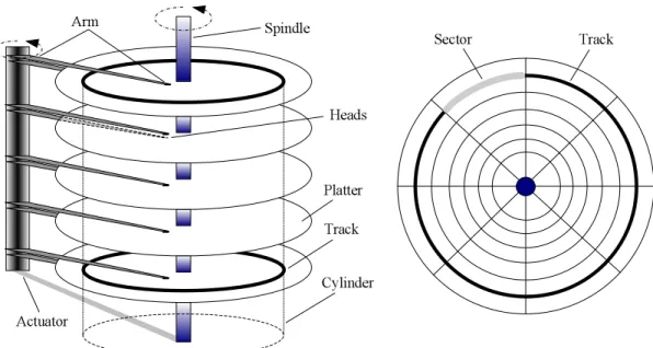
FIGURE 19.2: A typical disk.
file contains a number of records . Files are stored on the disk as a number of
consecu-tivepages where every page occupies a certain number ofsectors . Sectors are the smaller addressable unit of information on the disk (as will be explained shortly), consisting of a fixed number of bytes. When the database system needs to load a certain record in main memory for processing, first it has to identify the file and page that contains the record, and then issue a request to load that page from the disk. The file and page number have to be translated into a physical address on the disk. The disk controller is responsible for locating and transferring into main memory all the sectors composing the requested page. The most important characteristic of accessing information stored on the disk is that the actual placement of the requested sectors, as well as access patterns between consecutive requests, play a major role in the overall cost of such operations. The reason for this is directly related to the design and operational characteristics of the disk.
19.3.1
Design and Operation
A simplification of the internal view of a typical hard drive is illustrated in Figure 19.2. The
hard drive consists of three major components — theplatters, theheads, and theactuator.
The platters is were the actual information is stored. Each platter has two surfaces, and every surface can store several million bits of information. This information is hierarchically
grouped intocylinders , tracks , and sectors , as shown in the figure. Every cylinder is a
collection of tracks (the tracks with the same radii) and every track is a collection of sectors. The heads are responsible for reading and writing data on the surfaces of the platters and, thus, there is one head per surface. The actuator is a specially designed motor for accurately placing the heads over the precise track that needs to be read or written. For simplicity, all heads are rigidly mounted on the actuator arms and move only as a unit over exactly the same track on each platter.
The three components, spindle, heads and actuator, must be tightly and precisely coupled together for the hard drive to work correctly. Here is a brief overview of the operations
that need to take place in order to read a single byte from the disk. First, the address of the byte in terms of the disk’s geometry is determined in the form of a cylinder, head, and sector. Then, the disk controller has to determine if the requested information is already contained in the disk buffer, and if yes the read operation terminates. If not, then the controller has to activate the spindle motor to spin the drive to operating speed (if it is not spinning already), and instruct the actuator to move the heads on top of the requested cylinder on the platters of the disk. When the heads are in place, the controller activates the appropriate head to read the requested sector. The controller waits until the requested sector rotates underneath the head and immediately instructs the head to start reading the contents of the sector into the buffer. In what follows we describe in more detail these three major components of a hard drive.
Platters. The main disk assembly consists of a spindle upon which a number of circular
platters are firmly attached one on top of the other. The surface of the platters is were all the data is stored, using a thin media layer composed of magnetic material. A 0 or 1 bit is represented by orienting the magnetic material in one or the other direction. The bulk of the platter, the substrate, consists of a rigid and magnetically inert material upon which the
media layer is deposited. Older drives usediron oxide(commonly referred to as rust) as the
media layer, and substrates composed ofaluminum alloy, which is inexpensive, lightweight
and abundant. In newer drives the media layer is composed of special magnetic coatings
referred to asthin film mediawhich can support higher data density. Glass composites are
used for the substrate, which provide a much smoother surface.
Every platter has two active surfaces, and every surface can store a number of bits, dictated by the maximum data density supported by the magnetic material. The bits
stored on a surface are organized intotracks, which form concentric circles upon the platter.
Every track is divided into a number ofsectors(an angular section of a circle), interleaved
with gaps. Sectors are the smallest addressable unit of storage on the disk. Every read or write operation on the disk affects at least one sector at a time. In the rest we refer to a read or write operation as a disk I/O . All sectors contain a preset number of bytes (512 bytes for most disk drives). Gaps are necessary for separating consecutive sectors and also storing other information, like error correcting codes, synchronization and identification information, etc. In older drives all tracks consisted of the same number of sectors. Clearly, given that tracks with smaller radius have shorter circumference, the inner most tracks can hold much fewer bits than the outer tracks. Hence, a constant number of sectors per track means that outer tracks remain highly underutilized, not reaching their maximum data
density potential. Newer drives employ a geometry referred to aszoned bit recordingwhich
allows a variable number of sectors per group of tracks. This design maximizes the amount of data that can be stored on the disk but, on the other hand, necessitates designing more complex hard disk controllers that can support varying disk geometries.
Heads. The heads of the disk are by far the most sophisticated component of the hard
drive. They are suspended at the edge of the actuator arms, ridding as close as possible to the platters, on a very thin layer of air. For that purpose it is imperative that platters
are as smooth as possible in order to avoidhead crasheswhich would damage the surface of
the disk. The essential operation of a disk head is to transform magnetic fluctuations into electrical signals for reading, and vice versa for writing. The accuracy of the disk heads is one of the major factors that determine the maximum capacity that can be supported by a hard drive, limiting the maximum data density per track and track density per surface.
Actuator. The actuator assembly is responsible for placing the heads over the correct track on the platters. For simplicity, all heads are mounted together on the actuator arms and
move as a unit, being positioned over exactly the same track on their respective platters at the same time. Conceptually, the group of tracks at the same position on all platters is said
to form acylinder. Modern actuators use a device based on electromagnetic attraction and
repulsion for moving the arms, and a closed-loop feedback system that dynamically places the heads over the correct location. The feedback is provided by the heads themselves, which read special synchronization information stored on the platters by the manufacturer for locating the requested cylinder. The overhead of this information is not trivial and cannot be ignored. Substantial effort has been spent to try and reduce the amount of information needed for adjusting the heads. In older hard drives a whole surface was devoted for storing synchronization and identification information. In current technology this information is dispersed on the disk.
19.3.2
Physical and Operational Characteristics
Based on the previous discussion, the basic characteristics of a modern hard drive can be grouped into the physical properties of the platters, that define the maximum capacity of the drive, and the operational characteristics that define its performance in practice.
The physical characteristics can be summarized as follows:
• Number of Platters . The number of platters is directly proportional to the
overall capacity of the disk. Drives with one up to twelve platters can be found today, but a typical disk has about four platters, with each platter packing as much as 200 gigabytes of data.
• Track Density (TPI) . Increasing the number of tracks that can fit in a single
surface is important for reducing the number of platters required to reach a certain capacity. More platters mean more heads, which are very expensive, and a larger disk profile as well as weight. A typical hard drive can have as many as 100,000 Tracks Per Inch (TPI), but disks with 200,000 TPI have been manufactured.
• Linear Density (BPI). The linear density of a disk refers to the total number
of bits that can be packed consecutively in one inch of a track. Currently used magnetic materials and read/write heads can support up to 900,000 Bits Per Inch (BPI).
The basic operational characteristics are:
• Seek Time (ms) . Seek time is the time it takes the drive to position the heads
over the requested cylinder. It can vary from 0 ms if the heads are already over the right cylinder, and up to 15 to 20 ms for a full stroke, i.e., the time needed to move the heads over the entire width of the platters. The most commonly
used metric is the average seek timeneeded to move from a random cylinder to
another. A typical drive features an average seek time of less than 11 ms, but high-end drives with average seek times of less than 4 ms are currently being manufactured.
• Rotational Speed (RPM) . The rotational speed of the spindle of a hard drive
plays an important role on the transfer rate of the disk, since it directly affects latency . Since the rotation of the platters is independent of the head move-ment, after the actuator has positioned the heads over the correct cylinder the requested sector might not be directly under the head. The time it takes for the sector to move into position is called latency. Latency can be 0 ms in the best case, and almost a full rotation of the platters in the worst. Clearly, the higher
the rotational speed of the spindle, the smaller the average latency. A typical rotational speed for a modern hard drive is 7,200 Rounds Per Minute (RPM), i.e., it takes approximately 8 ms for a full rotation. In that case, assuming that on average the requested sector will be half way around the track after the head is positioned properly, the average latency is expected to be close to 4 ms. Drives featuring as high as 15,000 RPM do exist today.
• Internal Transfer Rate (Mb/s) . The transfer rate of a drive refers to the overall
speed with which data is transferred from the drive to main memory and vice versa. The transfer rate can be broken down into the internal media transfer rate and the interface transfer rate. Due to the mechanical nature of the internal transfer operation that is based on the rotation of the spindle, the internal transfer rate is what limits the overall data transfer rate of the drive. The internal transfer rate is the time it takes the drive to read one track in full. The transfer rate for a given track can be computed directly by using the total number of bits stored in the track and the rotational speed of the spindle. The more data that is stored in a track and the faster the rotational speed, the higher the internal data transfer rate. Since the number of bits per track varies depending on the radius, the internal data transfer rate depends on the position of the requested data on the surface of the disk. Typical hard drives feature average internal transfer rates close to 1,000 Megabits Per Second (MB/s).
• Sustained Transfer Rate (Mb/s). Essentially, the internal transfer rate refers to
the time it takes to read a single track of the disk. This rate does not take into account the head movement for repositioning the heads in case that the requested data does not fit in a single track. In practice, a single disk I/O needs to access
data that spans a large number of tracks. For that reason, thesustained transfer
rate is another measure that characterizes the performance of a hard drive for
large sequential reads that have to scan multiple tracks. Typical sustained rates for today’s hard drives are 650 Mb/s.
Let an imaginary hard drive contain four platters, 3.75 inches in diameter, with 100,000 TPI, 600,000 BPI, 512 bytes per sector, and feature a rotational speed of 7,200 RPM and an average seek time of 10 ms. Lets assume that the usable surface of the platter is between 0.2 and 3.7 inches. In that case, on average a track can hold approximately 449 kilobytes
(3.7·π·600,000 = 851 kilobytes for the outer most track and 0.2·π·600,000 = 46 kilobytes
for the inner most track). Thus, the drive can store 449·100,000·3.5 = 150 gigabytes per
surface, since it has an active surface of 3.7−0.2 = 3.5 inches and 100,000 tracks per inch.
Hence, the drive has a total capacity of 150·8 = 1,200 gigabytes (for a total of 8 surfaces),
including the space used for head placement information, sector gaps, error correcting codes, and other overhead. Since the drive supports 7,200 RPM the spindle makes a full rotation every 8 ms. Given the rotational speed of the drive and the average number of bytes per
track, the drive can read on average 1,000·449/8 = 438 Mb/s. Notice that the maximum
transfer rate when data is read from the outer most tracks is much larger in practice. An important consideration when computing the actual transfer rate of data is the average seek time for positioning the heads. Let’s assume that an 8 kilobyte block of data needs to be accessed from the disk. On average, we need 10 ms to position the heads and 4 ms latency to find the first of 16 sectors containing the data. If all sectors are consecutive on the same track, given the average transfer rate of the disk, it takes another 0.1 ms to read all 16 sectors, for a total of 14.1 ms to complete the transfer. On the other hand, in the worst case all sectors are scattered randomly on the disk, thus necessitating a total of 16 random seeks, costing 14 ms each. Obviously, the seek time dominates the overall cost of
the transfer. For that reason, efficient data storage organization is essential for improving performance.
19.3.3
Efficient Data Storage Organization
As the previous example illustrates, the organization of data on disk plays an important role on the performance of certain tasks. Ideally, we could take advantage of the operating principles of a hard drive to improve the performance and overall throughput of a database system. Given a typical hard drive, in an average of 14 ms per data access a modern CPU can execute several million instructions. In most practical situations, processing the data read from or written to the disk in one fetch operation requires at most a few thousand instructions. Evidently, the disk I/O cost becomes a dominant factor during the execution of an algorithm. For that reason it is crucial to design algorithms that minimize the total number of disk I/O requests. In addition, we would like to organize data on disk in a way that minimizes the total number of random seeks that are needed for completing all I/O requests, taking into account that multiple user request might be pending at any given time. For that reason, the best algorithms for main memory processing are not necessarily efficient when considering that data is also stored in secondary storage.
Since the amount of data processed in a typical database system far exceed main memory sizes in most practical applications, almost all database query and update algorithms are designed with these principles in mind. In addition, since most database systems have to serve multiple user requests simultaneously, effective scheduling algorithms for satisfying I/O requests that do not exhibit locality and refer to data that is potentially dispersed on the disk, need to be developed. Notice here that these issues are not limited to secondary storage only. Similar problems arise when considering all levels of the memory hierarchy. Given the access time gap between different levels of cache memory and main memory, by designing cache-conscious algorithms that use data structures with small memory footprints, operating mostly within the cache, the performance of a variety of database operations can improve even further.
Sequential Versus Random I/O
Many database operations, like sorting large relations on a given attribute, require continu-ous reading and writing of large amounts of related data. The efficiency of such operations can be substantially improved by strategically placing data that is read or written in tandem, in neighboring locations on the disk. Ideally, we would like to minimize the total movement of the heads for executing all the necessary I/O request for completing the operation, as was illustrated in Section 19.3.2.
The simplest way to guarantee minimal random head movements is to store the data sequentially on the disk, starting from a given sector of a given track and storing the data continuously on consecutive tracks of the same surface of the disk. Essentially, after one random seek for locating the first sector containing the requested data, we can read the the rest of the data by only performing sequential track-to-track seeks which are much faster than random seeks. In addition, we can also reduce the rotational latency in-between
track-to-track seeks by using a strategy calledcylinder skew. Suppose that we start storing the
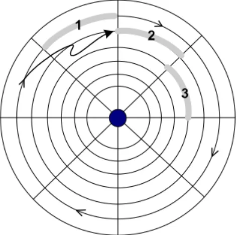
data on sector 1 of track 1. After track 1 is full, we continue storing the data on sector 2 of track 2, and so on. Clearly, after one full rotation of the disk, having read or written track 1 completely, a track-to-track seek will ideally place the heads over track 2 exactly before sector 2 is in position, resulting in minimal latency (see Figure 19.3). In practice, cylinder skew is much larger than one sector per track. Given current rotational speeds
1
2 3
FIGURE 19.3: An example of cylinder skew. A block of data is stored in consecutive tracks, where the first sector per track is skewed with respect to the previous track in order to reduce rotational latency.
and track-to-track head seek times, by the time the actuator places the heads over the next cylinder the platter might have performed as much as 20% of a full rotation. The principle though remains the same.
To speed-up sequential reads even further, we could organize the data in sequential cylin-ders instead of tracks, to take advantage of all disk heads simultaneously and reduce the track-to-track head movements as well. If we assume that disk heads can read in paral-lel then we minimize both track-to-track seeks and rotational latency by storing the data starting from the same sector on all tracks of each cylinder. Otherwise, if we are limited to reading from every head sequentially, we can reduce the rotational latency for reading consecutive tracks of the same cylinder by using a strategy similar to cylinder skew, referred
to ashead skew. If the beginning of the data is stored in sector 1 of track 1 on head 1, then
we continue storing the data on sector 2 of track 1 on head 2, and so on. After reading the track under head 1, by the time the controller switches to head 2, ideally sector 2 of track 1 will be located under head 2. Furthermore, a combination of head skew and cylinder skew can be employed for reading consecutive cylinders.
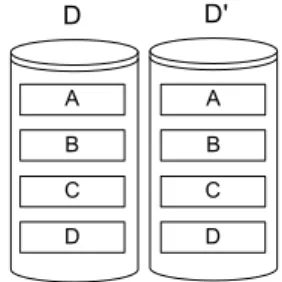
Finally, another approach for minimizing random seeks is to mirror the data using mul-tiple disks. The advantage of mirroring is, first, redundancy in case of disk failure and, second, that data can be read in parallel from all disks, hence reducing the overall I/O cost by a factor equal to the number of disks. The drawback is that this solution is much more expensive. A more detailed description of mirroring appears in Section 19.6.
Disk Scheduling Algorithms
Beyond large database operations that require sequential access to data, typical DBMS workload involves multiple, simultaneous user request, possibly on a variety of relations. In that case, the typical workload of a disk drive involves data that are dispersed on the disk, and almost all of the time result in a large number of random I/Os. Intuitively, in order to maximize system throughput it is necessary to schedule disk I/O request appropriately, depending on the specific location of each request on disk, such that head movement is minimized.
effort is made to minimize head movement. A better approach for lowering the average response time per request is to use Shortest Seek Time First (SSTF) . Given a queue of I/O requests, SSTF selects from the queue the request that results in the least amount of head movement, given the current location of the heads. Obviously, this strategy favors requests that exhibit locality. A disadvantage is that it might cause starvation . Requests that refer to data located far away from the current head position will experience heavy delays if a large number of requests that exhibit locality exist and are being serviced first, due to the position of the heads.
A different approach that avoids starvation is commonly referred to as the elevator algo-rithm or SCAN . The elevator algoalgo-rithm does not perform any random head movements at all. Instead, it continuously moves the heads across the disk from the inner cylinders to the outer and vice versa, and serves the next I/O request in the direction of the head movement. If no requests are pending on the current direction, the direction is immediately reversed. In the best case, a request that just arrived is serviced next. In the worst case a request for the outer most or inner most cylinder arrives right after the heads reversed direction and there exist a request for the other far end of the platter. The elevator algorithm does not have optimal throughput nor minimum average waiting time, but yields very good performance in practice for heavy workloads. As the number of requests increases, it is expected that these requests will be uniformly distributed over all cylinders of the disk resulting in perfect utilization of the head movement — at least one request per track-to-track seek.
Notice that with the elevator algorithm the cylinders in the middle of the platters are accessed twice as much as those at the inner and outer edges. A simple modification of the elevator algorithm is to allow the heads to move to one direction only. When the heads move to the end of the platters, they immediately seek back to the other end and start servicing requests in the same direction again. This has the advantage that all cylinders get treated fairly.
Table 19.3.3 shows an example of how these different scheduling algorithms work in practice. Let a hard drive with track-to-track seek time equal to 1 ms, and absolute seek time proportional to the number of tracks traveled (e.g., moving directly from track 1 to track 10 requires 10 ms). Assume that one request arrives every 1 ms, initially the heads are positioned over track 1, and the average rotational latency is 1 ms. The FCFS strategy processes requests in their arrival order and yields a total of 32 ms for servicing all requests. The SSTF strategy processes request 5 first, performing a random seek from track 1 to track 5 in 4 ms, plus 1 ms latency. By the time request 5 has been serviced, requests for tracks 6, 1, 10 and 2 have arrived since 5 ms have elapsed already. SSTF chooses to serve request 2 next, breaking a tie in terms of shortest head movement between 2 and 10. Next, it proceeds to track 1 and finally track 10 for a total of 24 ms. The SCAN algorithm begins servicing requests sequentially from track 1. A request for track 5 arrives first and is serviced directly in 5 ms including the rotational delay. The next request in the same direction is for track 6, continuing to track 10 and then reversing direction and servicing track 2 and finally track 1 for a total of 23 ms. Notice that if SSTF has chosen to service track 10 instead of 2 when breaking the tie, the schedule of SSTF would have been the same as SCAN. SCAN does not always result in the minimum total access time. It is not hard to construct examples where SSTF works much better than SCAN. SCAN does not minimize the individual, per request access time either. Notice that request 1 is serviced last, even though it arrives before 2 and 10.
Time 0 ms 1 ms 2 ms 3 ms 4 ms
Track 5 6 1 10 2
FCFS 5, 5 ms 6, 2 ms 1, 6 ms 10, 10 ms 2, 9 ms 32 ms SSTF 5, 5 ms 6, 2 ms 2, 5 ms 1, 2 ms 10, 10 ms 24 ms SCAN 5, 5 ms 6, 2 ms 10, 5 ms 2, 9 ms 1, 2 ms 23 ms
As we have already seen, relational and object oriented databases consist of a large number of relations with a well defined schema. Every relation consists of a collection of records or objects, where every record or object consists of a number of attributes. These attributes are assigned to specific data types, like strings, dates and real numbers. The DBMS stores a
relation in secondary storage as afile. A file consists of severalpages, where every page spans
a fixed number of sectors (e.g., a typical page size is 8 kilobytes for a total of 16 sectors per page). Each record of the relation is stored in one (or occasionally several) pages.
Straightforwardly, each record is associated with a unique physical address on secondary
storage, which is a combination of the file identifier corresponding to the relation that the record belongs to, a page within this file, and an offset within this page. The physical
address is also called therecord identifier.
In the previous section we saw essentially how the DBMS stores files and pages, such that fetching a single page or a single file from disk to memory (and vice versa) takes advantage of the low-level operational characteristics of disks. Nevertheless, at a higher level the DBMS treats a file or a page as a collection of records and, hence, has to also manage how records are organized into files and pages. In the simplest form, a file is an ordered collection of pages, where every page points to the location of the next page in the
file. This file structure is commonly referred to as aheap file. When a record needs to be
processed, (inserted, deleted, updated or moved) a disk I/O is performed for fetching the entire page containing the requested record into main memory. The appropriate page that needs to be accessed is deduced from the identifier of the requested record.
It is clear that the DBMS faces a number of problems when organizing records into files and pages, the most important of which are:
• Effectively representing records with a multiplicity of data types.
• Packing records into pages by minimizing unused space.
• Organizing records within a page for handling record updates efficiently.
• Handling records that span multiple pages.
• Organizing pages within files.
The rest of this section presents various approaches used by modern DBMSs for addressing these issues.
19.4.1
Physical Representation of Records
Consider the following SQL statement: CREATE TABLE Employees (
ID INTEGER PRIMARY KEY, Name VARCHAR(30), Address VARCHAR(255), BirthDate DATE
0 4
1234 Alan Turing 34
London, England
289 297
06 23 1912 (a)
0
1234 06 23 1912 Alan Turing London, England (b) 11 15
25 14
6 2
1 40
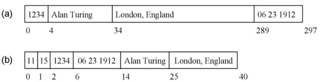
FIGURE 19.4: An example of fixed-length and variable-length records.
This statement creates a table containing records that can be represented either using fixed-length or variable-length encodings . In a fixed-length record representation every attribute within the record is represented using a fixed number of bytes. For instance, the above database schema shows that although some fields may have variable lengths, their maximum potential size is known in advance. Even though different employees may have addresses with different lengths, no employee will have an address that needs size larger than 255 bytes (which is either common knowledge or the fact that the DBMS will truncate longer addresses automatically). Therefore a fixed-length representation is to always assign
255 bytes to anAddress. Hence, we can encode a record belonging to theEmployeerelation
as a byte array by simply concatenating all attributes one after the other. In our example
a record will be encoded using 297 consecutive bytes; four bytes for theID, 30 bytes for
the Name, 255 bytes for the Address, and 8 bytes for the BirthDate. Parsing the record
is straightforward since we already know the exact size of every attribute and, thus, we know exactly where the data of every attribute begins and ends inside the byte array. The size of each attribute for a given relation is deduced by the database schema which can be stored in the system catalog , and accessed by the DBMS on demand. Although simple, the fixed-length representation wastes space. Even if a record has a short address which occupies only a few bytes, 255 bytes will be used.
In a variable-length record representation the number of bytes that an attribute value occupies depends on the actual size of this attribute within the specific record. Therefore a short address will occupy fewer bytes than a long address. In that case, delimiting two adjacent fields is made possible by using a special delimiter symbol (which is reserved and cannot appear in the actual data). An alternative approach is to keep some “header” information at the beginning of the record, which stores the actual length or the offset of the beginning of every attribute. With this information, by reading the header of the record we can immediately deduce the beginning and the end of all attributes. The header information also provides a natural way for representing NULL values , simply by setting the length of a NULL attribute to 0. In that case it might be beneficial to store in the header the length of the fixed-length attributes as well. That way, not only can we encode NULL values easily for all attributes, but we will not have to consult the system catalog in order to parse the record as well.
An example of a fixed-length record is shown in Figure 19.4(a). Here, no header infor-mation is needed for delimiting between two consecutive attributes, since the size of each attribute is known through the database schema. The total size of the record is 297 bytes. A variable-length record is shown in Figure 19.4(b). In this example, the record stores a small header in the first few bytes, then all the fixed-length attributes, and finally the variable-length attributes. The header stores two values. The first one is the length of the
Nameattribute. The second one is the length of the Address attribute. Since we already
attributes easily. Using this representation a record withnvariable-length attributes needs
onlynentries in the header. The total size of the record in this case is 40 bytes.
With a fixed-length representation updating any of the attribute values is straightforward; the old value is simply replaced by the new value. Nevertheless, in the variable-length representation when updating the variable-length attributes, two cases arise. In the first case the new value has length smaller than the old value, meaning that we need to compact the record by shifting all subsequent attributes to the left. In the second case the new value has length larger than the old value, and we need to expand the record by shifting all subsequent attributes to the right. In both cases, we also need to update the header with the length of the new value. Clearly, even though variable-length records result in storage space savings, they are more costly to maintain in the presence of record updates. To complicate matters even further, when multiple records are packed into a page and a record gets updated, not only do we need to shift the attributes within this record but, potentially, all subsequent records within the page need to be shifted as well. The following section discusses these issues.
19.4.2
Organizing Records Into Pages
Since the record size is typically much smaller than the page size, a page can hold several records. Many interesting issues arise when records need to be organized into pages in the presence of insertions, deletions and updates, especially when records need to be maintained in a particular order (e.g., in sorted order of the primary key).
1101. . . .
00000 00000 00000 00000
11111 11111 11111 11111
00000000000000 00000000000000 00000000000000 00000000000000
11111111111111 11111111111111 11111111111111 11111111111111
0 0 0 0
1 1 1 1
0
1
0
1 N
header
rec1 rec2 rec3
FIGURE 19.5: Page layout for fixed-length records.
Figure 19.5 is a simplified illustration of a disk page that stores fixed-length records. The page can be thought of as containing a number of slots with fixed size. The header of the page contains the number of records currently stored in the page and a bitmap signifying whether a slot holds a record or not. The total number of records is useful for quickly determining whether a page has empty slots or not. In the example, only slots 1, 2 and 4 are occupied. Initially, all bitmap entries are off. To insert a record, we locate the first available slot by scanning the bitmap. Then, we copy the record data into the corresponding slot and turn the appropriate bit on. To delete a record we simply switch the corresponding bit off. With this approach, a record can be identified using the page number and the index of the bit corresponding to the slot containing the record data. This scheme is also called anunpacked page . An alternative version calledpacked page exists, where no empty slots are allowed to exist in-between records. If a record is deleted, the last record in the page is moved into the newly freed slot. With this scheme there is no need to store a bitmap in the header. However, the deletion cost is higher.
Both these schemes are generally useful only for applications that do not need to keep track of individual record identifiers , since records change slots arbitrarily when deletions
occur, and dangling pointers to records might be introduced. If some application is
to a new slot, the record identifier becomes invalid since it points to an incorrect slot. A similar situation occurs when the record is deleted by some application, but there still exist other applications pointing to this records through its record identifier. Then, either these pointers refer to a deleted and, thus, invalid record or to a different, newer record that happened to replace the deleted entry in the freed slot. A more sophisticated record orga-nization policy can be used to alleviate these problems, which is also suitable for handling variable-length records.
. . . .
0 0 0 0 1 1 1 1 0 0 0 0 1 1 1 1 0000000000 0000000000 0000000000 0000000000 1111111111 1111111111 1111111111 1111111111 0 0 0 0 1 1 1 1 0 0 0 0 1 1 1 1 0 0 0 0 1 1 1 1 0000 0000 0000 0000 1111 1111 1111 1111 0 0 0 0 1 1 1 1N free size, offset size, offset rec1 rec2 header
FIGURE 19.6: Page layout for variable-length records.
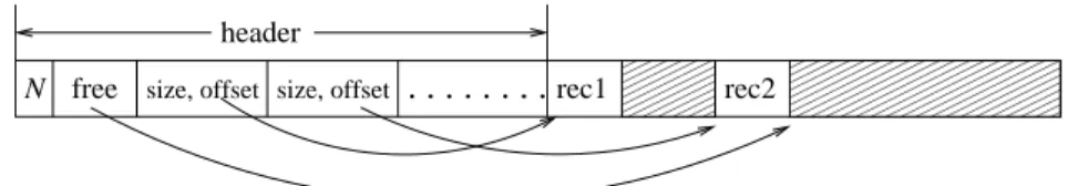
Figure 19.6 illustrates a disk page that stores variable-length records. In this case, since records have arbitrary sizes, whenever a new record needs to be inserted in the page we need to locate a slot with space large enough to store the new record. As records get inserted and deleted dynamically, we need to keep track of the empty space available inside each page. Moreover, we also need to be able to move existing records in order to keep most of the empty space contiguous at the end of the page, which will help for storing large records later on and also for minimizing the unused space in-between consecutive records. Another problem that arises when using variable-length records is the space lost whenever a record gets updated and the new values either decrease or increase the overall size of the record. If the record decreases in size, unused space is introduced in-between two consecutive records. If the record expands, then it might be necessary to relocate the record in case it does not fit in its current slot. A sophisticated record organization policy can be used to address all these issues and also to avoid problems with dangling pointers and pointers to records that have been relocated, as already discussed.
The solution is to keep a record directory in the header of the page. The directory
contains one entry per record, where every entry stores the length of the record and the offset to the beginning of the record’s data. The free space within the page starts after the end of the last record in the directory. A pointer to the beginning of the free space is stored in the header as well. The identifier of every record is the combination of the page number and the corresponding index of the record in the directory. When a new record needs to be inserted, a new entry is appended at the end of the directory and the record is stored at the beginning of the free space. If the free space is not large enough
to contain the record, then we need to compact the existing entries in order to reclaim
the space lost by deletions and updates. In that case we need to shift all existing records such that their data appear contiguously at the beginning of the page (after the header) and all free space contiguously at the end. Notice that relocating the record data within the page does not affect record identifiers since their corresponding index in the directory remains unchanged. For the same reason, a record deletion does not remove the entry of the deleted record from the directory but simply sets the length of the record to zero, which is a special flag denoting that the record corresponding to this directory entry has been deleted. Removing the entry from the directory would result in affecting the indices of
all subsequent directory entries and, as a side-effect, the corresponding record identifiers. Zeroed out directory entries can be reclaimed by re-using them for newly inserted records. Nevertheless, allowing directory entries to be reclaimed introduces once again problems with dangling pointers to deleted records, allowing the pointers to refer to either obsolete information, or information belonging to a newer record.
Since the record directory always increases in size as insertions and deletions occur (es-pecially when entries for deleted records are not reclaimed) it is possible for the directory size to exceed the total size preallocated for the header. A solution to this problem is to use an overflow page to store the directory, and store only a pointer to the overflow page in the header of the original page. Another solution is to store the header at the end of the page instead of the beginning, expanding the directory into the free space of the page as it grows.
Another problem that might arise is if a record cannot fit in a page even after the page has been compacted. In that case we can either allocate an overflow page to store the new record or store the record in a sibling page. In both cases we need to leave a forwarding address for that record in the directory of the original page. The forwarding address is simply a pointer to the overflow or sibling page.
Finally, another special situation arises for very large records that do not fit in a single page or occupy almost one page by themselves. In this case allocating a set number of pages per record might be space inefficient. Consider for example the case where a record occupies a little more than half the size of a page. In this case, only one record can fit per page, and almost half of the space within the page remains unused. Clearly, better space utilization will result by fragmenting entries between consecutive pages, in order to use the dead space. Fragmenting records can be handled easily by keeping with every fragment a pointer to the next fragment in the form of a forwarding address, as mentioned earlier. The lack of a forwarding address for a fragment signifies that the record is complete.
19.4.3
Organizing Pages Into Files
A DBMS stores data into files, where each file is a set of pages. A file can grow or shrink in size as data is inserted or deleted, and hence is a dynamic data structure that needs to be maintained efficiently. As already mentioned, the simplest file organization, the heap file , is an ordered collection of pages. File consistency is achieved either by linking every page
to the next in a linked list fashion by using pointers, or by maintaining a page directory
structure that keeps track of pages within the disk. Notice that the pages can be randomly scattered on disk, or sequentially stored for efficiency. More complex file organizations can be designed in order to be able to allocate free pages on demand whenever needed (especially when sequential file storage is necessary), and to be able to find pages with enough free space to hold a given record. For example, the page directory structure is a good candidate for storing per page information on available free space. By consulting the page directory, we can determine which page has enough space to store a given record directly, without the need to sequentially scan all pages in the file. Sophisticated file organizations are especially important when records need to be maintained in a specific order, e.g., sorted by some given
attribute. The advancedindexing techniquesthat will be discussed in the following chapter
are specially designed file storage organizations to specifically serve this purpose.
The DBMS processes records by initially fetching the corresponding pages from the disk into main memory. Given that a disk access is orders of magnitude slower than a memory access, it is imperative to limit as much as possible the number of disk I/O requests that need to be performed in order to complete a given task. An elegant idea for limiting the total number of disk accesses is to buffer pages into available main memory, such that subsequent operations on the same page do not trigger additional disk I/O. For that reason, all modern
database management systems implement their own sophisticatedbuffer manager. ∗
19.5.1
The Concept of Buffering
00000 00000 00000 00000
11111 11111 11111 11111
000 000 000 000
111 111 111 111 memory buffer
disk
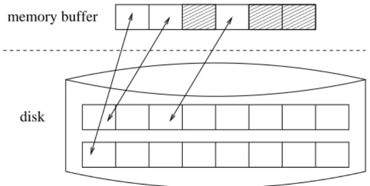
FIGURE 19.7: Illustration of buffering.
Figure 19.7 illustrates the concept of buffering. All records are stored on the disk as paginated files, as previously discussed. The job of the buffer manager is to maintain copies of several pages in a main memory buffer as well. Upon request of a page, the buffer manager checks if that page is already contained in the buffer. If it is, the disk I/O can be avoided. If not, the page is loaded from disk directly into the buffer. In the latter case two situations arise. In the first case the buffer has enough space to hold the new page. In the other case, the buffer is full and, hence, an old page needs to be evicted. Modern DBMSs implement various replacement policies for evicting pages from the buffer, which will be discussed in the next section. Assuming that a page is chosen for replacement uniformly at random, since that page might have been modified while residing in the buffer, before being discarded it might be necessary to first write it back to the disk. A modified page
is calleddirty. An unmodified page is calledclean . The buffer manager associates every
page with a dirty bit . If the bit is set, then the page has been modified and, thus, needs to be written back to the disk upon eviction. Otherwise, the page is clean and the buffer copy can be discarded directly.
Every page residing in the buffer is also associated with a pin count . A page can be
chosen for replacement only if its pin count is equal to zero. An application can pin a
∗The operating system on which the DBMS is running on, also has a buffer management component.
page in memory by incrementing itspin countby one. After a page is no longer needed, the
application that pinned the page shouldunpinit by decreasing itspin countby one. Pinning
pages in the buffer is useful when an application knows that this page will be accessed very frequently in the future and as a consequence should not be discarded unless if it is absolutely necessary. For example, such cases arise when processing the page directory structure of a file, a page that is being compacted, or when reorganizing various data structures and indices, like the B-tree, that will be discussed in the following chapter.
19.5.2
Replacement Policies
In general when the DBMS needs to pick a buffer page for replacement there are multiple strategies that can be used. Every strategy has advantages and disadvantages, depending on the data access distribution for a specific workload, the ease of implementation, the cost of managing buffered pages, and other factors. The most commonly used replacement policies are: First In First Out (FIFO), Least Recently Used (LRU), Most Recently Used (MRU), and Least Frequently Used (LFU).
FIFO replaces the page that entered the buffer before all other pages.
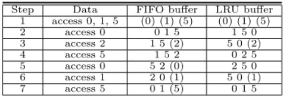
LRU is the most widely used policy. It replaces the page which has not been used for the longest time. LRU can be implemented simply by maintaining the buffer as a linked list and whenever a page is accessed, by moving it to the beginning of the buffer. Then we always pick the page at the end of the buffer for replacement. Table 19.1 shows a running example of the FIFO and LRU replacement policies. Let a buffer have a capacity of three pages and be initially empty. After the first three pages 0, 1 and 5 are loaded from disk, the buffer is full. (Here we enclose a page identifier in parentheses if the page needs to be loaded from disk.) To access page 0 in step 2, no disk I/O is needed for either FIFO nor LRU. However, we can observe a small difference. The LRU policy moves the most recently accessed page, which is 0 in this case, to the head of the queue. In Step 3, both policies need to load page 2 from the disk. Because the buffers are full, in both cases a page needs to be replaced. While FIFO replaces page 0 which entered the buffer first, LRU does not, because 0 has recently been used. Instead, LRU replaces page 1 which is the least recently used. In step 4, both schemes access page 5 in the buffer and therefore do not trigger a disk I/O. Once again in LRU page 5 is moved to the head of queue. Step 5 shows a difference in the I/O performance of the two schemes. In FIFO, page 0 needs to be loaded from disk, while in LRU page 0 is already present in buffer. Step 6 accesses page 1 which requires a disk I/O in both cases. Then in step 7, again by using LRU a disk I/O is avoided. Clearly, depending on the data access distribution the two policies can work equally well. Nevertheless, when
data accesses exhibitlocality of reference, where several pages are accessed many times in
a row, the LRU policy is by far superior to FIFO.
Step Data FIFO buffer LRU buffer 1 access 0, 1, 5 (0) (1) (5) (0) (1) (5)
2 access 0 0 1 5 1 5 0
3 access 2 1 5 (2) 5 0 (2)
4 access 5 1 5 2 0 2 5
5 access 0 5 2 (0) 2 5 0
6 access 1 2 0 (1) 5 0 (1)
7 access 5 0 1 (5) 0 1 5
Contrary to LRU, MRU replaces the most recently accessed page. MRU works best under a scenario where many long sequential scans of pages occur. In such cases LRU may suffer from sequential flooding . Consider, for example, a buffer with 9 pages and a file with 10 pages. If we sequentially scan the file multiple times, after the buffer is full for the first time, the LRU scheme will result in every single page access performing a disk I/O. MRU is much better in this case.
LFU counts the number of times that a page stored in the buffer has been used, and picks for replacement the one that has been used the least. This policy has the drawback that very frequently accessed pages will remain in the buffer forever, potentially causing starvation. To overcome this problem, a modification of this approach is compute the access frequency of every page (i.e., the number of accesses divided by the time the page has stayed in buffer), instead of simply the number of accesses.
19.5.3
Buffering Structured Pages
In this section we describe an interesting implementation issue relating to how we can buffer pages that store records with a known user-defined structure more efficiently. While a page can be viewed simply as an array of bytes on the disk in low-level, in reality it is typically understood by higher-level DBMS components or user applications as a collection of user-defined structures, e.g., a relational tuple or an object in object relational DBMSs. There are various advantages in injecting higher-level knowledge of the specific structure of the entries contained within pages at the buffer manager level. If the buffer manager understands pages simply as byte arrays, then every time a page entry needs to be accessed, it will have to be converted into its corresponding structured representation, which results into two severe efficiency problems. The first is the processing cost of converting an entry, which unnecessarily wastes processing power. The other is the fact that two copies of essentially the same data need to be kept in main memory, one unstructured within the buffer, and the other structured within the memory space of the application using the data. A better choice is to buffer each page entry directly as a pointer to its user-defined structure, the moment the page is inserted into the buffer. That way every entry is converted into a structured representation only once, and all higher-level components of the DBMS access directly the same copy of the structured data through the buffer. A drawback of this technique is that it breaks the data encapsulation and decoupling between the low-level buffer manager component of the DBMS and the higher-level components. In addition, using this technique it is fairly hard to support arbitrary user-defined data types dynamically. Issues related with this technique are discussed in more detail in [Zha05].
19.6
Disk Arrays
Single disk storage systems face some problems that require robust solutions towards two
main directions: 1. efficiency; and 2. availability. Regarding efficiency, although buffering
offers a great boost in performance by keeping part of the data in fast storage, disk accesses are still a bottleneck in I/O bounded applications (e.g., multimedia databases, scientific databases). Therefore, more efficient secondary storage systems are required. Regarding availability, a single disk system is vulnerable to a number of threats such as data loss or unavailability of the whole system due to storage failure. Both cases are considered catastrophic, taking into account that data is priceless and system failure is not an option for systems that should be operational 24 hours a day, 7 days a week. Even though an automated backup solution could alleviate the problem to a certain extend, data loss is still
possible, especially for frequently updated databases. Essentially, availability reflects the percentage of time the data is available. If the disks fail, the time interval required to either repair or substitute the disk has a significant impact on availability. The more time the data remains off-line the more the availability of the storage system is impacted. Taking into account the previous observations, the question is if there is a mechanism that tackles both problems (efficiency and availability). The answer is affirmative and one of the tools
to achieve this is thedisk array.
19.6.1
Efficiency and Availability
The disk array has been introduced in [PGK88], under the term RAID (Redundant Array of Inexpensive Disks) . In this section, we briefly discuss efficiency and availability issues, which motivated the development of the disk array technology.
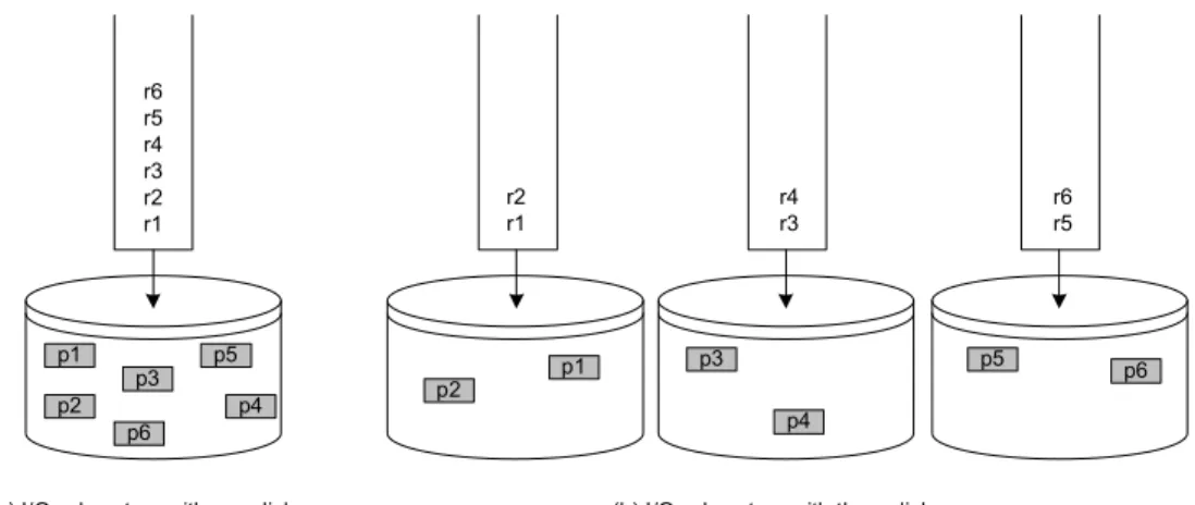
Assume that a computer system is supported by a single disk device. This means that every I/O request is directed to a single queue and will be served by a single disk, according to the scheduling technique supported. Without loss of generality, assume that FCFS is used to serve the I/O requests. Figure 19.8(a) shows the contents of the I/O queue at a
given time instance. Letr1,r2,r3,r4,r5andr6be the pending requests, waiting for service,
where the requestriasks for the disk pagepi. Moreover, letT(ri) denote the time required
for requestri to be served. Evidently, the timeTtotal1disk required to serve all requests is given
by:
T1disk total =
6
X
i=1 T(ri)
This means that requestr6will have to wait all previous requests to be served first. The
question is if the utilization of more disk devices can help in reducing the service time.
Assume that the data are distributed in three disks, such that disk pagesp1,p2 reside on
the first disk, pages p3, p4 reside on the second disk, and pagesp5, p6 reside on the third
disk. An I/O subsystem with three disks is illustrated in Figure 19.8(b). In this setting, each disk maintains its own queue of requests. Therefore, a request for a specific page is directed to the appropriate disk queue and it is served by the corresponding disk device. The time required to serve all requests is given by:
p1 p2
p3 p5
p6
p4 r6 r5 r4 r3 r2 r1
p1 p2
p3 p4
p5
p6 r2
r1
r4 r3
r6 r5
(a) I/O sybsystem with one disk (b) I/O sybsystem with three disks
T3disks
total =max{T(r1) +T(r2), T(r3) +T(r4), T(r5) +T(r6)}
The previous equation states that the time required to serve all six requests is dominated
by the “slowest” disk. The optimal speed-up with this approach would beT3disks
total =
T1disk total
3 . Although it is hard to achieve such an ideal performance improvement, we expect that the time required to serve all requests will decrease by increasing the number of disks. Evidently, such an improvement is possible only if the requests are directed to different disk devices. For example, if all requests involve data that reside on the first disk only, then no improvement is possible. However, by carefully distributing the data to the available disks, significant performance improvements may be achieved. To achieve this, knowledge of data access distribution is required in order to perform effective data placement.
Although the distribution of the data to more than one disks helps in improving perfor-mance, it does not help in increasing availability. Data availability is strongly related to fault tolerance, which measures the ability of a system to continue its normal operation even if one (or more) of its components is non-operational. By using more than one disks, not only fault tolerance is not being improved, but the probability that the disk array as a whole will fail increases. An important disk parameter is the Mean Time To Failure (MTTF) which is given in the disk specifications provided by the manufacturer. This parameter measures the average time interval which guarantees no hardware failure of the disk device. The larger the MTTF the more reliable the disk is. The problem arises when more than one disk is used. In such a case, if any of the disks fails the whole array has a major problem.
More formally, if MTTF(1) denotes the MTTF of a single disk and MTTF(N) denotes the
MTTF of an array ofN identical disks, then the following holds:
MTTF(N) = MTTF(1)
N
For example, if a disk device has an MTTF of 500,000 hours and 100 such disks are used in an array, the MTTF of the array drops to 5,000 hours which is about 200 days of operation. This simple example demonstrates that availability is seriously affected if we just use multiple disks to solve the efficiency problem. What we need is to improve efficiency without sacrificing data availability. This can be achieved by providing more intelligent disk arrays, equipped with sophisticated mechanisms towards increased fault tolerance, by surviving hardware failures. The primary target is to be able to access the data even if one of the disks is non-operational.
19.6.2
RAID Levels
Research in disk array technology has focused on attacking the availability problem, by incorporating sophisticated mechanisms. The result of this research is a number of proposals which differ with respect to data distribution across multiple disk devices. Therefore, a number of different RAID levels have appeared. The simplest approach is to just use multiple disk devices where each disk hosts different parts of the data. This approach is
termedRAID level 0, and as it has been demonstrated in the previous section, it does not
tackle the availability problem at all, since it does not provide any fault tolerance (if a disk fails, the corresponding data is not accessible). By using RAID level 0, only the efficiency issue is handled. Under this scheme, each data file is split into a number of blocks, and the blocks are distributed to the available disks without using any redundancy. This technique