NEW CONSTRUCTION ROUGH OPENING DIMENSIONS - SWING OUT UNITS WITH A BUMPER SILL
Swing out rough opening dimensions are identical to those above, except that the 6’8” & 8’ 0” heights which are each reduced by7/8”.Entry Door System
Installation Instructions
IMPORTANT
Read these instructions completely before beginning installation. Please use caution when completing any building project.
• Safety glasses • Phillips headscrewdriver • Power drill or screw
gun with #2 Phillips head bit • 1/8” drill bit • Hammer • Level • Tape measure • Square • Step Stool • Caulking gun with
tube of latex caulk • #8 x 3”exterior
grade screws • Gloves
ROUGH OPENING DIMENSIONS
Before removing your old door, or preparing the rough opening for a new door, verify that the size of the door purchased will properly fit your opening.
NEW CONSTRUCTION ROUGH OPENING DIMENSIONS - SWING IN UNITS
DOOR SIZE OPENING
TYPE
DOOR WITH 14” SIDELITE1
WIDTH 6’8” HT. 8’0” HT. SINGLE DOUBLE
WOOD FRAME UNIT1 Single Door 2’6” Rough Brick 2’8-1/4” 2’10” 6’10” 6’10-3/4” 8’3” 8’3-3/4” 3’11-3/4” 4’1-1/2” 5’3-1/4” 5’5”
IMPORTANT:This door system has a 1-1/4” threshold height which allows for approximately a 1” opening clearance over carpet, tile or other floor coverings. If this clearance is not sufficient, the complete door system should be installed on a wood spacer high enough to ensure swing clear-ance. If a spacer is used, the rough open-ing height must be adjusted accordopen-ingly. •Consult your retailer/lumber yard for size availability of these and other sidelite sizes.
•Brickmold dimension is measured from outside edge of brickmold on door unit.
Add 11/2” to the rough opening width if a 2” x 4” is used between the door and a single sidelite and 3” if 2”x4” studs are used between the door and double sidelites. 5’5-1/4” 5’7” 5’9-1/4” 5’11” 6’3-1/4” 6’5” 7’9-3/4” 7’11-1/2” 8’1-3/4” 8’3-1/2” 8’9-3/4” 8’11-1/2” 4’1-3/4” 4’3-1/2” 4’5-3/4” 4’7-1/2” 4’11-3/4” 5’1-1/2” 6’6-1/4” 6’8” 6’10-1/4” 7’0” 7’6-1/4” 7’8” 1’4-1/4” 1’6” 8’3” 8’3-3/4” 8’3” 8’3-3/4” 8’3” 8’3-3/4” 8’3” 8’3-3/4” 8’3” 8’3-3/4” 8’3” 8’3-3/4” 8’3” 8’3-3/4” 6’10” 6’10-3/4” 6’10” 6’10-3/4” 6’10” 6’10-3/4” 6’10” 6’10-3/4” 6’10” 6’10-3/4” 6’10” 6’10-3/4” 6’10” 6’10-3/4” 2’10-1/4” 3’0” 3’2-1/4” 3’4” 3’8-1/4” 3’10” 5’2-3/4” 5’4-1/2” 5’6-3/4” 5’8-1/2” 6’2-3/4” 6’4-1/2” – – – – Rough Brick Rough Brick Rough Brick Rough Brick Rough Brick Rough Brick Rough Brick Single Door 2’8” Single Door 3’0” Single Door 3’6” Double Door 5’0” Double Door 5’4” Double Door 6’0” Sidelite Only Head Brickmold Head Jamb Square Level Latch Jamb Latch Brickmold Sweep
Skid Plate (Plastic) or Skid Board (Wood or Cardboard
Threshold must be on a flat level solid surface. Hinge Jamb
Hinge
Hinge Brickmold
Threshold/Sill
PREPARATION OF ROUGH OPENING
ABOUT YOUR DOOR
FIGURE 1
FIGURE 2
TABLE 1
Determine rough opening size from Table 1. Make sure that opening is the proper size, and is plumb, square, and level before installing door. The three sides of the opening must be in the same plane (not twisted) to assure proper operation (Figure 2).
NOTE: If you require a 20 minute smoke and draft rated opening, the gap between the door frame and rough opening must not exceed 1/8” on the top and sides.
Door Slab
STEP 1:
Work safely with tools,
wear safety glasses
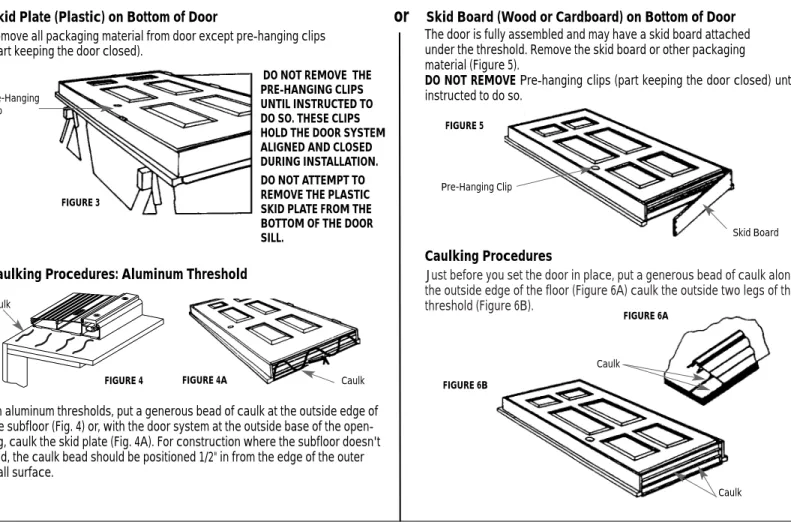
Just before you set the door in place, put a generous bead of caulk along the outside edge of the floor (Figure 6A) caulk the outside two legs of the threshold (Figure 6B).
The door is fully assembled and may have a skid board attached under the threshold. Remove the skid board or other packaging material (Figure 5).
DO NOT REMOVEPre-hanging clips (part keeping the door closed) until instructed to do so. Pre-Hanging Clip Caulk Caulk Caulk Caulk
PREPARATION OF DOOR SYSTEM FOR INSTALLATION
Skid Plate (Plastic) on Bottom of Door
or
Skid Board (Wood or Cardboard) on Bottom of Door
Caulking Procedures: Aluminum Threshold
Caulking Procedures
FIGURE 3 FIGURE 4 FIGURE 5 FIGURE 6A FIGURE 6B FIGURE 9 FIGURE 7 FIGURE 9A FIGURE 8 FIGURE 4ASTEP 2:
SETTING THE DOOR SYSTEM
STEP 3:
STEP 4:
TEMPORARILY SECURE HINGE JAMB
A Door system without the threshold attached requires assembly before installation. Refer to the final assembly instructions included with your threshold.On aluminum thresholds, put a generous bead of caulk at the outside edge of the subfloor (Fig. 4) or, with the door system at the outside base of the open-ing, caulk the skid plate (Fig. 4A). For construction where the subfloor doesn't end, the caulk bead should be positioned 1/2" in from the edge of the outer wall surface.
Place the bottom of he door unit in the center of the rough opening (Figure 7 (1). Tilt the door unit up and into position (Figure 7 (2).
DO NOT REMOVE THE PRE-HANGING CLIPS UNTIL INSTRUCTED TO DO SO. THESE CLIPS HOLD THE DOOR SYSTEM ALIGNED AND CLOSED DURING INSTALLATION. DO NOT ATTEMPT TO REMOVE THE PLASTIC SKID PLATE FROM THE BOTTOM OF THE DOOR SILL.
Remove all packaging material from door except pre-hanging clips (part keeping the door closed).
Pre-Hanging Clip Skid Board Shim Shim 1 2
Plumb the hinge jamb, or sidelite jamb on the hinge side (only one jamb on a double door) and temporarily hold it in place with two #8 x 3” screws through the jamb approximately 2” below the top and center hinges (Figure 8).
NOTE:For 8’0” door use two #8 x 3”screws through the jamb approximately 2” below the top and lower-middle hinges (Figure 8).
Go inside through another entry and shim the unit in place using pairs of tapered shims (Figure 9, 9A, and 9B). Place shims directly behind all three hinges ( 4 hinges on a 8’0” door) on the hinge jamb. Check for uniform gap between frame and rough opening. Go outside and install #8 x 3’ screws through the jams at the shim locations
It is critical that the complete assembly be plumb, square and not twist-ed to operate properly.
CAUTION: USE PROPER LIFTING TECHNIQUES. DOOR UNIT IS HEAVY AND MAY REQUIRE TWO PEOPLE TO LIFT.
1/8” Maximum Allowable Gap (Fire Rated Doors)
FIGURE 9B
IMPORTANT:When installing a door with sidelites on concrete, construction adhesive should be used under the jambs at the edges of the active door to firmly anchor it. Make sure the door system is correctly positioned and operates properly before the adhesive cures. Once the adhesive hardens, it will be impossible to adjust the position of the threshold without breaking the bond.
Plumb and square the latch jamb. Shim between the jamb and rough (3 locations between latch and deadbolt, and opposite hinges) opening to assure proper alignment. Verify that the latch jamb is plumb and square. Temporarily secure the latch jamb with three #8 x 3” drywall screws at shim locations.
IMPORTANT:Do not shim the head jamb of a single door system. On door systems with sidelites, shim in the area above the joint between the door unit and the sidelite unit and secure this area with additional drywall screws.
NOTE:The gap between the door frame and rough opening must not exceed 1/8” for 20 minute smoke and draft rated openings. Gaps exceeding 1/8” must be solidly shimmed (Figure 9A).
ALIGN THE DOOR SYSTEM
STEP 5
ADJUST THE LATCH JAMB
STEP 6
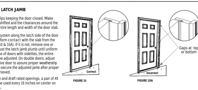
Examine the weatherstrip system along the latch side of the door to see if it is in equal or uniform contact with the slab from the top to the bottom (Figures 10 & 10A). If it is not, remove one or both of the screws and adjust the latch jamb plumb until uniform contact is made. In the case of doors with sidelites, the entire latch jamb sidelite should be adjusted. On double doors, adjust the hinge jamb of the inactive door to assure proper weatherstrip contact at the astragal. Re-secure the adjusted jamb after proper weatherstrip contact is achieved.
NOTE:For 20 minute smoke and draft rated openings, a pair of #8 x 3” drywall screws must be used every 16 inches on center on both latch and hinge jambs.
Remove the pre-hanging clips keeping the door closed. Make sure that the door has not shifted and the clearances around the door are equal along the entire length and width of the door slab.
FIGURE 10 FIGURE 1OA
FIGURE 12 FIGURE 12A Incorrect Correct #9 x 2 1/4” Gaps at top or bottom
Four #9 x 2-1/4” wood screws are provided with single doors and eight are provided with double doors. Two of these screws are to be installed on the jamb leaf of the top hinge in the holes closest to the weatherstrip (Figure 12). One each of these screws should be installed on the remaining hinges in the top hole closest to the weatherstrip. Drill a 1/8” pilot hole in the security screw locations before installing the screws. After the screws are installed, open and close the door to re-check clearances. If the clearances are not uniform, adjust these screws and shims to achieve proper clearances.
NOTE:(8’ door) has six #9 x 2-1/4” wood screws which are provided with single doors, and twelve are provided with double doors. Two of these screws are to be installed on the jamb leaf of the lower-middle hinge in the holes closest to the weatherstrip (Figure 12A).
Remove the 2 temporary screws on the hinge jamb from step 4 (2” from top and bottom of door).
ADJUST THE HINGE JAMB
STEP 7
When a door system with sidelites is installed on a wood floor, the jambs where the sidelite and door meet must be secured to the floor. Drill and countersink two guide holes through the inside of the jambs into the floor at the locations shown (Figure 14). Install two #8 x 3” drywall screws per sidelite. Assembly is now complete. Trim the interior as desired.
Install two #8 x 3” drywall screws along the head jamb of double door systems for additional reinforcement as shown (Figure 13). Do not shim the head jamb.
ADDITIONAL FASTENING FOR DOUBLE DOORS AND DOOR SYSTEMS WITH SIDELITES
STEP 8
FIGURE 13
FINISHING REQUIREMENTS
Must be Product Line painted by*
Wood Frame & Trim - All 45 days Utility/basic & Builder Series Door Slab and lite frame 45 Days Sta-Tru Plus Door slab and lite frame 1 Year Smooth Fiberglass Door Slab 45 Days Woodgrain Fiberglass Door Slab 45 Days
Pre-finished Door Slab 2 Years
* Pre-finished Door Slab only needs finish preparation and re-coating with a UV resistant, exterior grade, clear varnish or polyurethane (i.e. marine spar varnish). All Stanley Doors come with a paint ready surface. Further prime painting
is not recommended.
Prior to painting an exterior grade putty, or paintable caulk, must be used to cover all nail and screw holes in the frame. These fillers must be dry before the painting process can start.
Before applying a paint finish, lightly scuff sand the entire steel door panel with 220 grit sandpaper,. (Figure 16) DO NOT SAND FIBERGLASS DOORS!
wipe the door and jamb surfaces with mineral spirits to remove any oil, dust or debris. (Figure 17). Followed by a water and detergent solution to remove any residue.
Finish painting outside of your door and jambs with high qualityexterior oil or latex based house paint and the inside with a high qualityinterior or exterior latex paint. The complete door surface, including decorative trim, jamb and door edges must be painted.
IMPORTANT:
ALWAYS PAINT IN A WELL-VENTILATED AREA. BE SURE TO COVER WORK AREA WITH A DROP CLOTH.
FOLLOW ALL WARNINGS AND INSTRUCTIONS FROM THE PAINT MANUFAC-TURER.
WARNING: DARK COLOR DOORS, AND DOORS WITH ATTACHED STORM DOORS, WILL BECOME VERY HOT TO THE TOUCH IN DIRECT SUNLIGHT. Do not paint weatherstrip and do not close the door until the paint is dry (see paint manufacturer’s specifications on minimum drying time).
Painting the jamb, header and brick mold within 45 days of installation, and the door slab within the time specified (see Table 2) after installation, will greatly increase the performance of the door system, and is required to maintain product warranty. Depending on region, repainting every 1 to 7 years will be required.
NOTE: While most paints are dry to the touch within a couple of hours, they may not be fully cured and hardened for up to 2 weeks. Please see paint manufacturer’s instructions for more information.
TIP: To yield a smoother finish remove the door from the hinges and place door in a horizontal position, such as on top of sawhorses or clean bench top (Figure 18). Paint one side and let dry, flip door and paint the other side. To remove in swing doors use a center punch and a hammer to tap the bottom of the hinge pins to remove (Figure 19). On outswing doors remove the screws from the hinges of the door.
See the WOOD GRAIN FINISHING INSTRUCTIONS pamphlet for fiberglass staining instructions.
FINISHING INSTRUCTIONS
STEP 10
FIGURE 16 FIGURE 17 FIGURE 18 FIGURE 19
TABLE 2
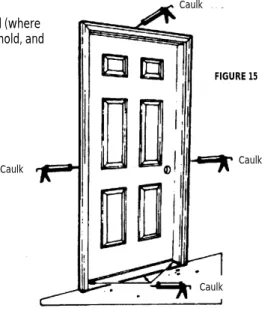
IMPORTANT:Caulk around entire frame on exterior wall (where brickmold meets wall) at intersection of jamb and threshold, and along exterior nose of threshold (Figure 15).
CAULK THE DOOR
STEP 9
FIGURE 15 Caulk Caulk Caulk CaulkSteps to test threshold seal of your Stanley Door.
1.Close door on a piece of paper placed over the threshold. (Figure 21)
2.Pull paper between the sweep of the door and the threshold.
3.If the threshold is properly adjusted, you should feel some tension, but if the paper tears,
the door’s seal is too tight. If there is no tension on the paper, the door’s seal is too loose.
To properly adjust the threshold seal if it is too tight. 1.Adjust rail by tightening all screws (turn clockwise 1/2 turn.
2.Repeat seal test. If paper does not slide beneath door with a feeling of ten-sion, repeat Step 2. Re-test seal.
3.Continue testing threshold until it is properly adjusted.
To properly adjust the threshold seal if it is too loose. (WARNING: Do not increase height by more the 1/4”)
1.Adjust rail by loosening all screws (turn counter-clockwise) 1/2 turn.
2.Repeat seal test. If paper does not slide beneath door with a feeling of ten-sion, repeat Step 2. Re-test seal.
3.Continue testing threshold until it is properly adjusted. Once your Stanley Door has been properly installed, it is very important to
test its threshold for an adequate seal and proper adjustment. The threshold is factory adjusted to 1 1/4”. This is the optimum threshold height under most conditions. The sweep of your Stanley Door should not be excessively compressed. A compression of 1/16” will be adequate.
1. Hinge Jamb 2. Hinge Pad 3. Rail 4. Threshold 5. Adjusting Screws 6. Latch Seal 7. Lock Jamb 8. Sweep
1.
2.
3.
4.
5.
6.
7.
8.
FIGURE 20 FIGURE 22 FIGURE 21SILL ADJUSTMENT (ADJUSTABLE RAIL THRESHOLD ONLY)
STEP 11
INSTALL FOAM PADS
STEP 12
INSTALL LATCH AND/OR DEADBOLT HARDWARE
STEP 13
1.Add a bead of caulk at both ends of rail where the rail meets the jambs. 2.On door lock-side of rail, affix beige latch seal vertically to jamb on top of
caulk where jamb and rail meet. Push seal into caulk.(Figure 20) 3.On door-hinge side of rail, affix hinge pad (black pad) horizontally to jamb
on top of caulk where jamb and rail meet. Push seal into caulk.Figure 20)
NOTE: For Double Doors: Test the seal for the active and inactive doors. Adjust the threshold seal if necessary by following the instructions above. Once threshold seal is properly adjusted. affix beige latch seal vertically so bottom of seal is resting where rail and astragal (the center jamb between both doors) meet. Remember to replace both hinge pads.
See hardware manufactures instructions for installation details.
NOTE: Included with the door are two (2) latch/deadbolt adapters (Figure 22). These trim parts are used on the door slab behind the latch and/or deadbolt to give the door edge a more finished appearance.
© 2002 The Stanley Works • New Britian CT. 06053 • http://www.stanleyworks.com Part #00824 Rev. 06/02
Entry Door
Duration
Basic Door
5 years
Builder Series Door
10 years
Sta-Tru
®Plus Door
Lifetime
Fiberglass Door
Lifetime
LIMITED WARRANTY
Stanley Doors ("Stanley") warrants its entry doors to be free of deficiencies in materials and workmanship to the original purchaser. This LIMITED WARRANTY is applicable only to doors installed in single family, owner occupied dwellings and its duration is specified in the WARRANTY DURATION TABLE above. The product price is consideration for this LIMITED WARRANTY.
This LIMITED WARRANTY is subject to the exceptions, exclusions, disclaimers, and limitations described below and is in lieu of all other warranties, including the implied warranty of merchantability. This LIMITED WARRANTY gives the purchaser specific legal rights. You may have other rights which vary by state.
Exceptions to LIMITED WARRANTY:
•
Doors installed in non-owner occupied dwellings (e.g. apartments, duplexes, etc.) are warranted up to 10 years from the date of purchase or from the date of manufacture. The only exception is Basic Doors which are warranted up to 5 years from the date of purchase or from "the date of manufacture." (date of manufacture establishes effective date of LIMITED WARRANTY if there is no documentation).•
Decorative glass and wood component parts, manufactured by Stanley, are warranted to be free from deficiencies in materials and workmanship up to 10 years from the date of purchase or manufacture. The only exception is Basic Doors which are warranted up to 5 years from the date of purchase or manufacture.•
Doors installed within 5 miles from any body of saltwater are warranted up to 10 years from the date of purchase or manufacture. The only exception is Basic Doors which are warranted up to 5 years from the purchase or manufacture.•
Doors assembled with components supplied by manufacturers other than Stanley are not covered by this LIMITED WARRANTY.•
Stanley reserves the right to discontinue or modify any of its products, including the color, door style and/or glass design, without notice. Stanley may sub-stitute products or components of comparable quality or price for discontinued or modified products.Events LIMITED WARRANTY does not cover:
•
Condensation on the interior surface of the door or glass.•
Incidental or consequential damages and/or expenses. Some states do not allow the exclusion or limitation of incidental or consequential damages, so this specific limitation or exclusion may not apply to you.•
Finishing not complete before the following deadlines after installation: 45 days for wood frame and trim, 45 days for Basic/Builder/Woodgrain Fiberglass/ Smooth Fiberglass, 1 year for Sta-Tru®Plus Doors, and 2 years for Pre-Finished Fiberglass Doors.•
Any deficiencies that result from:- installation not in strict adherence with Stanley's written instructions; - maintenance not in strict adherence with Stanley's written instructions; - improper handling and storage;
- modification or alteration of the door system by anyone who is not a authorized Stanley representative; - vandalism, misuse, neglect, impact by foreign objects, acts of god, fire, explosion or other casualty;
- air pollutants, including acid rain, and exposure to harmful chemicals or normal weathering caused by exposure to the elements; - minor air and water infiltration in severe weather conditions;
- any failure of the structure/building/foundation in to which the door is installed;
- any other causes beyond Stanley's control and not related to the manufacturing process.
LIMITED WARRANTY exclusive remedies:
•
During the applicable LIMITED WARRANTY period, Stanley will REPLACE, REPAIR, OR REFUNDthe amount paid for any door determined by an authorized Stanley representative or authorized Stanley distributor to be deficient in material and workmanship. These remedies do not include labor charges or other expenses in connection with repair, removal, or installation of either the original or a replacement product. Such labor and/or expenses are the responsibility of the customer.•
If a Stanley representative determines replacement is required, the terms of this LIMITED WARRANTY may be prorated depending upon purchase dates. Basic and Builder Series Doors are not prorated. Sta-Tru®Plus and Fiberglass Doors are prorated in the following manner: from 10 years or less from the dateof purchase, no prorating is applicable; from 11-20 years, it's prorated at 50%; and from 21 years on up, it's prorated at 25%.
•
In lieu of replacement or repair, Stanley reserves the right to refund the amount paid by the original purchaser of the door, not including labor and/or addi-tional expenses.•
Stanley will not be responsible for any repair or replacement costs in excess of the cost of the replacement door.•
All costs incurred for repair or replacement must be previously authorized in writing by Stanley.Claim Procedure: