Draft
EG 201 400-1
V1.1.1
(1998-11)
ETSI GuideHybrid Fiber Coax (HFC) access networks;
Part 1: Interworking with PSTN, N-ISDN,
Internet and digital mobile networks
Reference
DEG/NA-080201 (cyo90icq.PDF) Keywords
access, digital, internet, interworking, ISDN, mobile, network, PSTN
ETSI
Postal address
F-06921 Sophia Antipolis Cedex - FRANCE Office address
650 Route des Lucioles - Sophia Antipolis Valbonne - FRANCE
Tel.: +33 4 92 94 42 00 Fax: +33 4 93 65 47 16
Siret N° 348 623 562 00017 - NAF 742 C Association à but non lucratif enregistrée à la
Sous-Préfecture de Grasse (06) N° 7803/88
Internet [email protected]
Individual copies of this ETSI deliverable can be downloaded from
http://www.etsi.org
Copyright Notification
No part may be reproduced except as authorized by written permission. The copyright and the foregoing restriction extend to reproduction in all media.
Contents
Intellectual Property Rights...5
Foreword ...5
Introduction ...5
1
Scope ...6
2
References...6
3
Definitions, symbols and abbreviations ...9
3.1 Definitions ... 9
3.2 Symbols ... 10
3.3 Abbreviations... 10
4
Service Requirements ...10
5
Functional requirements...11
6
Reference Configuration and Reference Points...12
6.1 The HFC access network general architecture and boundaries ... 12
6.2 Digital section for HFC access network... 13
6.3 General reference configuration for HFC Access Networks ... 14
6.3.1 User Port Function ... 14
6.3.2 Service Port Function ... 15
6.3.3 Core Function... 15
6.3.4 HFC User Interface Function ... 15
6.3.5 HFC Access Node Function ... 16
6.3.6 HFC Transport Network Function... 16
6.3.7 AN System Management Function... 16
6.4 HFC Access Network configuration for the considered networks ... 16
6.5 Reference Points ... 17
6.5.1 Reference points at the user interface side ... 17
6.5.2 Reference points at the network interface side ... 18
7
User Interfaces ...18
7.1 Broadcast UNI ... 18
7.1.1 Analogue Broadcast UNI ... 18
7.1.1.1 Interface references... 19
7.1.1.2 Protocol stack reference... 19
7.1.2 Digital Broadcast UNI... 20
7.1.2.1 Interface references... 20
7.1.2.2 Protocol stack and peer communication stack reference ... 20
7.2 PSTN UNI ... 21
7.2.1 Interface references ... 22
7.2.2 User Interface functions - POTS Cable Network Termination... 22
7.2.3 Protocol stack and peer communication stack reference configuration... 22
7.3 N-ISDN UNI... 23
7.3.1 Interface references ... 24
7.3.1.1 Basic access ... 24
7.3.1.2 Primary access ... 24
7.3.2 User Interface functions - N-ISDN Cable Network Termination ... 24
7.3.3 Protocol stack and peer communication stack reference ... 25
7.4 Internet Terminal UNI ... 26
7.4.1 Interface references ... 26
7.4.2 User interface functions - IP Cable Network Termination ... 27
7.4.2.1 Definition... 27
7.4.2.2 Functions and Technology... 27
7.4.3 Protocol stack and peer communication stack reference ... 28
7.5.1 Interface references ... 29
7.5.2 User Interface functions - Leased Cable Network Termination ... 30
7.5.3 Protocol stack and peer communication stack reference ... 30
8
Service Node Interfaces (SNI) (Access Node Interface) ...30
8.1 Broadcast Service ... 30
8.2 PSTN Service specific Service node... 30
8.2.1 Interface references ... 31
8.2.2 Network interface functions - PSTN Cable Line Termination ... 31
8.2.3 Protocol stack and peer communication stack reference configurations ... 31
8.2.3.1 Protocol stacks... 31
8.2.3.1.1 V5.1N interface... 31
8.2.3.1.2 V5.2N interface... 32
8.2.3.2 Protocol peer configurations... 32
8.2.3.2.1 V5.1 interface... 33
8.2.3.2.2 V5.2 interface... 34
8.3 N-ISDN Service specific Service node ... 34
8.3.1 Interface references ... 34
8.3.2 Network interface functions -N-ISDN Cable Line Termination... 35
8.3.3 Protocol stack and peer communication stack reference configurations ... 35
8.3.3.1 Protocol stacks... 35
8.3.3.1.1 V5.1N interface... 35
8.3.3.1.2 V5.2N interface... 35
8.3.3.2 Protocol peer configurations... 36
8.3.3.2.1 V5.1 interface... 36
8.3.3.2.2 V5.2 interface... 37
8.4 PSTN/N-ISDN Modular Service node... 38
8.4.1 Interface references ... 38
8.4.2 Network interface functions - PSTN/N-ISDN Cable Line Termination... 38
8.4.3 Protocol stack and peer communication stack reference configurations ... 39
8.4.3.1 Protocol stacks... 39
8.4.3.1.1 V5.1N interface... 39
8.4.3.1.2 V5.2N interface... 39
8.4.3.2 Protocol peer configurations... 40
8.4.3.2.1 V5.1 interface... 41
8.4.3.2.2 V5.2 interface... 42
8.5 Internet network ... 42
8.5.1 Interface references ... 43
8.5.2 Network interface functions - IP Cable Line Termination ... 43
8.5.3 Protocol stack and peer communication stack reference ... 43
8.5.3.1 Protocol stacks... 43
8.5.3.2 Protocol peer communication ... 44
8.6 Leased lines Specific Service network... 44
8.6.1 Interface references ... 45
8.6.2 Network interface functions - Leased Line Cable Line Termination... 45
8.6.3 Protocol stack and peer communication stack reference configurations ... 45
9
Internal HFC Access Network Aspects...45
9.1 Interface references... 45
9.2 Internal HFC Access Network Structure... 45
9.3 HFC Access network channel structure and protocols... 46
Bibliography...47
Intellectual Property Rights
IPRs essential or potentially essential to the present document may have been declared to ETSI. The information pertaining to these essential IPRs, if any, is publicly available for ETSI members and non-members, and can be found in SR 000 314: "Intellectual Property Rights (IPRs); Essential, or potentially Essential, IPRs notified to ETSI in respect
of ETSI standards", which is available free of charge from the ETSI Secretariat. Latest updates are available on the
ETSI Web server (http://www.etsi.org/ipr).
Pursuant to the ETSI IPR Policy, no investigation, including IPR searches, has been carried out by ETSI. No guarantee can be given as to the existence of other IPRs not referenced in SR 000 314 (or the updates on the ETSI Web server) which are, or may be, or may become, essential to the present document.
Foreword
This ETSI Guide (EG) has been produced by ETSI Technical Committee Network Aspects (NA), and is now submitted for the ETSI standards Membership Approval Procedure.
The present document is part 1 of a multi-part EG covering the Hybrid Fiber Coax (HFC) access networks, as identified below:
Part 1: "Interworking with PSTN, N-ISDN, Internet and digital mobile networks".
Introduction
Cable TV networks are more and more used for other services than just broadcast service. At the user side service terminals other than TV and radio are attached. At the terminal side, the head end needs to interwork with a number of service related networks. The present document presents a number of different interfaces at the user side and the network side and shows how the HFC access network interconnects them, both for user and signalling data.
1
Scope
The present document is focussed on the interworking between HFC networks and other networks. The different user equipment and the different user network interfaces to the access network have an influence on the interworking, and as such, are also considered.
It may be the case that an independent cable operator operates an HFC access network that has no interface to a switching network at all. In this case the HFC network is maybe not regarded as an access network, but nevertheless the network may provide services to its customers beyond just Broadcast services. This case is beyond the scope of the present document, since no interworking is involved. If, on the other hand, an independent cable operator has interfaces to other switching networks, the contents of the present documents applies.
The present document considers the following public telecommunication networks: - public switching telephone network;
- narrowband ISDN network; - internet;
- leased lines networks.
Other public telecommunication networks will be considered in a later document
Looking at broadcasting, it is considered as a service rather than as a network. The interfaces for broadcast services at the HFC access network are however also considered. Analogue and digital broadcasting are handled separately.
2
References
The following documents contain provisions which, through reference in this text, constitute provisions of the present document.
• References are either specific (identified by date of publication, edition number, version number, etc.) or non-specific.
• For a specific reference, subsequent revisions do not apply.
• For a non-specific reference, the latest version applies.
• A non-specific reference to an ETS shall also be taken to refer to later versions published as an EN with the same number.
[1] ETR 306: "Transmission and multiplexing (TM); Access networks for residential customers". [2] ITU-T Recommendation G.960 (1993): "Access digital section for ISDN basic rate access". [3] ITU-T Recommendation G.962 (1993): "Access digital section for ISDN primary access at
2048 kbit/s".
[4] ITU-T Recommendation G.963 (1993): "Access digital section for ISDN primary access at 1544 kbit/s".
[5] ITU-T Recommendation G.964 (1994): "V-interfaces at the digital local exchange (LE) – V5.1 interface (based on 2048 kbit/s) for the support of access network (AN)".
[6] ITU-T Recommendation G.965 (1995): "V-interfaces at the digital local exchange (LE) – V5.2 Interface (based on 2048 kbit/s) for the support of access network (AN)".
[7] ISO/IEC 10038 (1993): "Information technology - Telecommunications and information exchange between systems - Local area networks - Media access control (MAC) bridges".
[8] ISO/IEC 8802-2 (1997): "Information technology - Telecommunications and information exchange between systems - Local and metropolitan area networks- Specific requirements - Part 2: Logical link control".
[9] ISO/IEC 8802-3 (1997): "Information technology - Telecommunications and information exchange between systems - Local and metropolitan area networks - Part 3: Carrier sense multiple access with collision detection (CSMA/CD) access method and physical layer specifications". [10] ITU-T Recommendation G.902: "Framework Recommendation on functional access networks
(AN) – Architecture and functions, access types, management and service node aspects". [11] ETR 148: "Private Telecommunication Network (PTN); Integrated services architecture for high
speed private networks".
[12] ITU-T Recommendation N.51: "Definitions for application to international television transmissions".
[13] ITU-T Recommendation I.112: "Vocabulary of terms for ISDNs".
[14] ITU-T Recommendation Q.512: "Digital exchange interfaces for subscriber access". [15] ITU-T Recommendation Q.551: "Transmission characteristics of digital exchanges".
[16] ITU-T Recommendation Q.552: "Transmission characteristics at 2-wire analogue interfaces of digital exchanges".
[17] EN 50083-1: "Cabled distribution systems for television and sound signals - Part 1: Safety requirements".
[18] EN 50083-2: "Cabled distribution systems for television and sound signals - Part 2: Electromagnetic compatibility for equipment".
[19] EN 50083-3: "Cabled distribution systems for television and sound signals - Part 3: Active coaxial wideband distribution equipment".
[20] EN 50083-4: "Cabled distribution systems for television and sound signals - Part 4: Passive coaxial wideband distribution equipment".
[21] EN 50083-5: "Cabled distribution systems for television and sound signals - Part 5: Headend equipment".
[22] EN 50083-6: "Cabled distribution systems for television and sound signals - Part 6: Optical equipment".
[23] EN 50083-7: "Cabled distribution systems for television and sound signals - Part 7: System performance".
[24] ETS 300 429: "Digital Video Broadcasting (DVB); Framing structure, channel coding and modulation for cable systems".
[25] ITU-T Recommendation J.83: "Digital multiprogramme systems for television, sound and data services for cable distribution".
[26] ITU-T Recommendation H.222.0: "Information technology – Generic coding of moving pictures and associated audio information: Systems".
[27] EN 300 001: "Attachments to the Public Switched Telephone Network (PSTN); General technical requirements for equipment connected to an analogue subscriber interface in the PSTN".
[28] ITU-T Recommendation I.411: "ISDN user-network interfaces – Reference configurations". [29] ITU-T Recommendation Q.921: "ISDN user-network interface - Data link layer specification". [30] ITU-T Recommendation Q.931: "ISDN user-network interface layer 3specification for basic call
[31] ITU-T Recommendation I.430: "Basic user-network interface – Layer 1 specification". [32] ITU-T Recommendation I.431: "Primary rate user-network interface – Layer 1 specification". [33] ETS 300 288: "Business TeleCommunications (BTC); 64 kbit/s digital unrestricted leased line
with octet integrity (D64U); Network interface presentation".
[34] ETS 300 418: "Business TeleCommunications (BTC); 2 048 kbit/s digital unstructured and structured leased lines (D2048U and D2048S); Network interface presentation".
[35] ETS 300 448: "Business TeleCommunications (BTC); Ordinary quality voice bandwidth 2-wire analogue leased line (A2O); Connection characteristics and network interface presentation". [36] ETS 300 449: "Business TeleCommunications (BTC); Special quality voice bandwidth 2-wire
analogue leased line (A2S); Connection characteristics and network interface presentation". [37] ETS 300 451: "Business Telecommunications (BTC); Ordinary quality voice bandwidth 4-wire
analogue leased line (A4O); Connection characteristics and network interface presentation". [38] ETS 300 452: "Business Telecommunications (BTC); Special quality voice bandwidth 4-wire
analogue leased line (A4S); Connection characteristics and network interface presentation". [39] ETS 300 766: "Business TeleCommunications (BTC); Multiple 64 kbit/s digital unrestricted leased
lines with octet integrity presented at a structured 2 048 kbit/s interface at either or both ends (D64M); Connection characteristics and network interface presentation".
[40] ETS 300 686: "Business TeleCommunications (BTC); 34 Mbit/s and 140 Mbit/s digital leased lines (D34U, D34S, D140U and D140S); Network interface presentation".
[41] ETS 300 687: "Business TeleCommunications (BTC); 34 Mbit/s digital leased lines (D34U and D34S); Connection characteristics".
[42] ETS 300 688: "Business TeleCommunications (BTC); 140 Mbit/s digital leased lines (D140U and D140S); Connection characteristics".
[43] ETS 300 689: "Business TeleCommunications (BTC); 34 Mbit/s digital leased lines (D34U and D34S); Terminal equipment interface".
[44] ETS 300 690: "Business TeleCommunications (BTC); 140 Mbit/s digital leased lines (D140U and D140S); Terminal equipment interface".
[45] TBR 25: "Business TeleCommunications (BTC); 140 Mbit/s digital unstructured and structured leased lines (D140U and D140S); Attachment requirements for terminal equipment interface". [46] ETS 300 166: "Transmission and Multiplexing (TM); Physical and electrical characteristics of hierarchical digital interfaces for equipment using the 2 048 kbit/s - based plesiochronous or synchronous digital hierarchies".
[47] ETS 300 167: "Transmission and Multiplexing (TM); Functional characteristics of 2 048 kbit/s interfaces".
[48] ETS 300 347: "V interfaces at the digital Local Exchange (LE); V5.2 interface for the support of Access Network (AN)".
[49] ETS 300 324: "V interfaces at the digital Local Exchange (LE); V5.1 interface for the support of Access Network (AN)".
[50] ITU-T Recommendation I.361: "B-ISDN ATM layer specification".
[51] ITU-T Recommendation I.363: "B-ISDN ATM Adaptation Layer specification".
[52] ITU-T Recommendation I.432: "B-ISDN User-Network Interface – Physical layer specification". [53] ETS 300 800: "Digital Video Broadcasting (DVB); Interaction channel for Cable TV distribution
[54] ITU-T Recommendation J.112: "Vocabulary of terms for ISDNs".
[55] EN 50083-9: "Cable networks for television signals, sound and interactive services --Part 9: Interfaces for CATV/SMATV headends and similar equipment for DVB/MPEG-2 transport streams".
[56] EN 50083-8: "Cabled networks for television signals, sound signals and interactive services --Part 8: Electromagnetic compatiblity for networks".
[57] EN 50083-10: "Cable networks for television signals, sound signals and interactive services --Part 10: System performance for return paths".
[58] IETF RFC 894 (1984): "A standard for the transmission of IP Datagrams over Ethernet Networks". [59] IETF RFC 1042 (1988): "A standard for the Transmission of IP Datagrams over IEEE 802
Networks".
3
Definitions, symbols and abbreviations
3.1
Definitions
For the purposes of the present document, the following definitions apply:
Access Network: an implementation, comprising those entities which provide the required transport bearer capabilities for the provision of telecommunication services between a Service Node Interface and each of the associated user-network interfaces. An Access Network can be configured and managed through a Q3 interface. In principle there is no restriction on the types and the number of UNIs and SNIs which an Access Network may implement. The access network does not interpret (user) signalling.
Access Node (AN): a node providing access to the public network [ETR 148].
broadcast organisation: organisation which is concerned with sound and/or television broadcasting [ITU-T Recommendation N.51].
broadcast network: network providing sound and/or television signals to the user, either directly to the user or via an HFC access network.
CATV: used as a general term for "cable television" (historically used to indicate "Community Antenna TeleVision" - a centralized installation of television antennas that serves a community of users).
downstream direction: direction from the network towards the subscriber.
digital section: the whole of the means of digital transmission of a digital signal of specified rate between 2 consecutive reference points. The term should be qualified by the type of access supported, or by a prefix denoting the V interface at the digital section bounderies.
Head End (HE): (definition in HFC access network context): equipment in an HFC access network, providing interfaces between the HFC Access network and one or more other networks, and providing an RF communication interface with the user interface functions.
Hybrid Fiber/Coax (HFC) Access Network: a mixed fibre and coaxial network architecture using FDM transmission technology based on RF frequencies, in which fibre links are used for the main distribution path, while coaxial links are used as the final link into the users' premises.
network interface functions: functions belonging to the Head End in a HFC access network.
service node: a network element that provides access to various switched and/or permanent telecommunication services. In case of switched services the SN is providing access call and connection control signalling, and access connection and resource handling [ITU-T Recommendation G.902].
service node interface: the interface between an Access Network and a Service Node. (ITU-T Recommendation G.902: The interface which provides customer access to a service node).
telecommunication network: a set of nodes and links that provides connections between 2 or more defined ports to facilitate telecommunication between them [ITU-T Recommendation I.112].
upstream direction: direction from the subscriber towards the network.
User Interface Functions (UIF): functions in an access network, interacting with the user equipment, and providing a RF communication interface with the Head End it is connected to.
User Network Interface (UNI): the interface at which the user equipment is connected to the network.
3.2
Symbols
For the purposes of the present document, the following symbols apply: <R>C Reference point related to BroadCast service <R>I Reference point related to IP-based service <R>L Reference point related to Leased Line Service <R>N Reference point related to Narrowband ISDN service <R>T Reference point related to Telephony service C64 User channel of 64 kbit/s
D16 Data channel of 16 kbit/s D64 Data channel of 64 kbit/s
M Reference point at a service interface residing in a network
P Reference point at a service interface residing at the border of a network Q3 Telecommunication Network Management Interface
V5 Reference point at the SNI interface of an Access Network Z Reference point at the UNI interface of analogue telephony
3.3
Abbreviations
For the purposes of the present document, the following abbreviations apply:
AN Access Network
ANI Access Network Interface CATV Community Antenna TeleVision
CF Core Function
FDM Frequency Division Multiplex
FE Function Element
HFC Hybrid Fiber Coax
HE Head End
LE Local Exchange
PC Personal Computer
PRA Primary Rate Access
SN Service Node
SNI Service Node Interface SPF Service Port Function UIF User Interface Functions
UPF User Port Function
4
Service Requirements
An HFC Access Network may support a number of telecommunication services and telecommunication service components. The basic function of an HFC Access Network is that it uses RF frequencies for transportation of the information between the user side and the network side of the access network. As such, the information, including both signalling and user information, must be mapped in one way or another into the RF frequency spectrum and the traditionally used frequency bands for Radio and Television. In addition to the downstream traffic, some upstream traffic may be required. Depending upon the type and bandwidth of the information, different solutions may be required for different services to be supported.
HFC Access Networks may support (but are not required to support) the following Telecommunication services. Supporting" means that the HFC AN does not provide the services itself, but provides the necessary channels, control, management and security functions for transporting the service information between Service Node and User equipment.
- Basic service: Radio and TV distribution service.
- Telephony service, its supplementary services, and all value added services such like telefax, DECT and voice data modem services.
- Internet services: basic TCP/IP en UDP/IP communication and Internet services ftp, telnet, e-mail, usenet, www and gopher.
- Mobile services as defined for GSM, DCS 1800 and IMT-2000. - B-ISDN services as defined in the F.700 and F.800 series. - X25 based data services (PSPDN services).
The service component information types to be supported are: - Sound: voice, music,...
- Video: TV-programme, movie...
- Data: files, static pictures, text, low speed data, high speed data, real-time data...
5
Functional requirements
The fundamental principles of an access network and a HFC access network in particular are reflected by the following functional requirements:
- an (HFC) AN is used in order to multiplex/demultiplex the signalling and data streams from UNIs in a cost effective manner and then to present this information stream to the SN in a manner such that the SN can determine the source or sink UNI;
- concentration shall be supported across a V5 reference point as an option (although it shall always be possible to guarantee bandwidth for user ports who require such a facility such as the security services);
- the HFC AN does not interpret (user) signalling. Signalling for Telecommunication services should be handled as near to transparently as possible. This means that the contents of signalling messages should not be checked unless it is unavoidable;
- the V5 reference point shall not be limited to a single physical interface (for redundancy and to allow more user ports to be connected);
- it is not a requirement for local switching to be carried out within the Access Network itself, either under SN control or under local control;
- the responsibility for call control and associated connection control resides in the SN (i.e. the HFC AN may have no knowledge of ongoing services and the call state during normal operation);
- tones and announcements should be generated in the service node(s) and not in the access networks themselves, except for local ringing and some kind of announcement when the user is not reachable from the service node (e.g. all access network lines busy);
- selection of the service provider by the HFC AN based on user signalling information shall not be possible, because this would require SN functionality in the HFC AN.
However, for ATM based access types the HFC AN shall support access to different SNs through a single UNI at the same time by using the corresponding VPs associated to these SNs via provisioning. In this case the selection of the service provider is a matter of the user terminal and does not concern the HFC AN or the SNI;
- time critical management functions which require real time co-ordination between HFC AN and SN shall be performed by communication across the V5 reference point;
- technology specific functions, such as control of echo cancellers which might be required in a radio based access network, shall not be supported unless they are already supported by either V5 (in the case of narrowband services) or B-ISDN (in the case of broadband services);
- charging information is only provided by the SN. This information may be passed over the V5 reference point when a user requires it as part of the service to which he has subscribed and is not passed over the V5 reference point as a means of providing information for use by the HFC AN. Also tones and announcements shall be generated in the SN and not in the HFC AN;
- if multicasting is provided in the HFC AN, this shall be allowed to be performed in the SNI to UNI direction only. Otherwise multicasting is presumed to be a service provided by the SN;
- the V5 reference point at the SN has a signal structure which is a multiplex of several accesses of the same or of different access types.
The HFC AN may serve service specific SNs or modular SNs as defined in ITU-T Recommendation G.902. Service affecting faults in the AN need to be advised to the SN in real time.
Signalling streams need to be protected.
A HFC AN makes use of RF signals for user, signalling, and maintenance information in the HFC Transport Network. A HFC AN supports basically distribution (analogue and digital audio/video) services, but may be bi-directional and may support (not provide!) telephony service, IP based service, data services, video on demand services.
The downstream bandwidth (towards the user) of an HFC is in principle much bigger than the upstream bandwidth.
6
Reference Configuration and Reference Points
6.1
The HFC access network general architecture and
boundaries
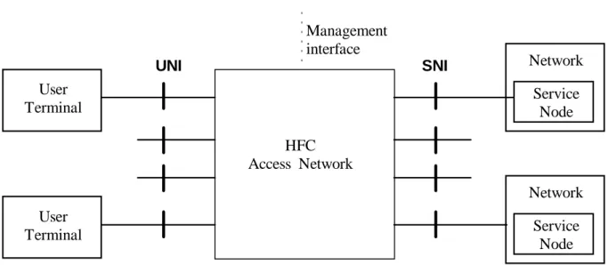
The following figure shows a general architecture of the HFC access network, in relation to its surrounding entities. The figure is based on figure 1/ITU-T Recommendation G.902.
Management
interface
User
Terminal
SNI
UNI
HFC
Access Network
User
Terminal
Service
Node
Network
Service
Node
Network
Figure 1: General Access Network architecture and boundaries
This picture shows:
- that the HFC Access Network is able to connect multiple users to multiple networks; the relation is a many to many relation, where only some users can be connected to one network, and otherwise a user can only be connected to some networks, depending upon subscription;
- the interface to the user is in general called UNI (User Network Interface), whatever the interface;
- the interface to a network is called SNI (Service Node Interface), whatever the telecommunication network. ATM Forum uses ANI (Access Network Interface), the difference is that signalling interpretation in the AN is allowed. It is possible that the access network has a interface for management purposes.
6.2
Digital section for HFC access network
It is possible that the HFC access network is located at a certain (medium or long) distance from the service node. To this purpose a digital section may be used , which may be called a "Feeder digital section", since it is there to 'feed' access networks located closer to the user. The digital section is guaranteeing that what goes in, also comes out in the same format. So the (V-) interface at both ends of the digital section is the same. The digital section can be SDH-based, PDH-based, or any other transmission scheme preserving the format. The Feeder digital section can be either point-to-point or point-to-point-to-multipoint-to-point.
Following figure shows the Feeder digital section at the SNI.
HFC access Network Head End Service Node Feeder Digital Section V5 HFC access Network Head End HFC access Network Head End V5 V5 V5
6.3
General reference configuration for HFC Access Networks
The following figure shows the reference configuration for an HFC Access Network Based. It is based on the functional architecture of a general Access Network as shown in ITU-T Recommendation G.902, figure 3.HFC Access Network
HFC AN System Management Function
Service Port Function Core
Funct.
Network Management Interface
PC
MC
SNI [4] UNI
[3] HFC User Interface Function[6]
Cable network function Cable network function Telecom-munication Network (some type [2]) Customer equipment [1] Core Funct. HFC Transport Network Function User Port Function HFC Head End [5] HFC Access Node Function
NOTE: The customer equipment may consist of some terminals, possibly interconnected by private switching equipment; terminals may be connected in a wireless way.
The access network may be connected to the following telecommunication network types : PSTN, N-ISDN, B-N-ISDN, PSPDN, Internet, Mobile and Digital Mobile networks, Satellite networks, and Cable networks.
One Access network in general serves multiple UNI interfaces.
One Access network in general may serve multiple telecommunication networks, of the same or different types; a specific HFC Access Node type is needed for a specific telecommunication network type. The Head End may group a number of access nodes providing the interfacing to a number of telecommunication networks of the same or different type.
One Access network in general may serve multiple customer equipment, of the same or different types; a specific HFC User Interface Function type is needed for a specific customer equipment type.
Figure 3: General HFC Access Network reference configuration
6.3.1
User Port Function
The User Port Function (UPF) adapts the specific UNI requirements to the core and management functions. The AN may support a number of different accesses and user network interfaces which require specific functions according to the relevant interface specification and the access bearer capability requirements, i.e. bearers for information transfer and protocols. The User Port Function functionality are related to the terminal (customer) equipment connected to it. Other terminal equipment in general needs different User Port Function functionality.
Examples of User Port general functionality are: - termination of the UNI functions; - A/D conversion;
- signalling conversion;
- handling of the UNI bearer channels/capabilities; - testing of UNI;
- maintenance of UPF; - management functions; - control functions.
6.3.2
Service Port Function
The Service Port Function (SPF) adapts the requirements defined for a specific SNI to the common bearers for handling in the core function and selects the relevant information for treatment in the AN system management function. The SPF functionality’s are related to the Telecommunication Network type connected to it. Other Telecommunication Network type in general needs different SPF functionality’s.
Examples of Service Port general functions are: - termination of the SNI functions;
- mapping of the bearer requirements and time critical management and operational requirements into the core function;
- mapping of protocols if required for particular SNI; - testing of SNI;
- maintenance of SPF; - management functions; - control functions.
6.3.3
Core Function
The Core Function (CF) is located between the UPF and SPF to adapt the individual user port bearer or service port bearer requirements into common transport bearers. This includes the handling of protocol bearers according to the required protocol adaptation and multiplexing for transport through the AN. The core function can be distributed within the AN.
Examples of core functions are: - access bearer handling:
- conversion of the information to/from RF format; - bearer channel concentration;
- signalling and packet information multiplexing; - circuit emulation for the ATM transport bearer. - management functions;
- control functions.
6.3.4
HFC User Interface Function
The HFC UIF is the combination of the UPF and the CF at the user side of the HFC Access Network. It interfaces to (a) specific user equipment(s) and converts/deconverts signals into/from a format suitable for the HFC Transport network.
6.3.5
HFC Access Node Function
The HFC Access Node Function is the combination of the SPF and the CF at the network side of the HFC Access Network. It interfaces to (a) specific telecommunication network(s) and converts/deconverts signals into/from a format suitable for the HFC Transport network.
6.3.6
HFC Transport Network Function
The HFC Transport Network Function (TF) provides the paths for the transport of common bearers between different locations in the AN and the media adaptation for the relevant transmission media used.
Examples of transport functions are: - multiplexing function;
- cross connect function including grooming and configuration; - management functions;
- physical media functions.
6.3.7
AN System Management Function
The AN System Management Function (AN-SMF) co-ordinates the provisioning, operations and maintenance of the UPF, SPF, CF and TF within the AN. Further it co-ordinates operation functions with the SN via the SNI and the user terminal via the UNI as defined in the relevant interface specifications.
Examples of AN system management functions are: - configuration and control;
- provisioning co-ordination; - fault detection/indication;
- usage information and performance data collection; - security control;
- co-ordination of time critical management and operation requirements for the UPF and the SN via SNI; - resource management.
The AN-SMF communicates with a Telecommunication management network via a Network Management interface for the purpose of being monitored and/or controlled and with the SN-SMF via the SNI for real-time control requirements according to the AN management functions and the SNI specification.
6.4
HFC Access Network configuration for the considered
networks
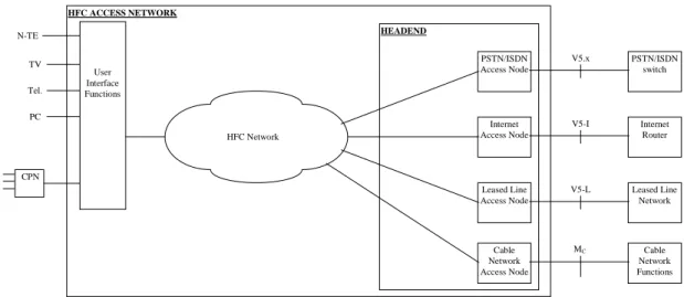
The HFC Access Network configuration in figure 3 is based on the general architecture and reference configuration, and is applied to the different considered telecommunication networks in the present document.
The configuration shows interworking between an HFC access network and the following other networks (see note): - PSTN;
- N-ISDN; - Internet;
- Leased Lines Network.
NOTE: The interworking between an HFC access network and B-ISDN or satellite networks is outside of the scope of the present document
MC HFC ACCESS NETWORK HEADEND Internet Router Leased Line Network PSTN/ISDN switch PSTN/ISDN Access Node Internet Access Node Cable Network Access Node Leased Line Access Node V5.x V5-I V5-L HFC Network User Interface Functions TV Tel. PC CPN Cable Network Functions N-TE
NOTE: This figure only shows a functional architecture. It does not indicate which functions may belong to which network operator. Depending on the choice of the boundary between operators, there may be additional features required in the interface definition.
Figure 4: HFC Access Network configuration for the considered networks
The figure also identifies some of the interfaces and the interworking units.
The interworking configuration outlined in figure 3, illustrates the situation where different networks interconnects with a common node access node headend. This headend acts as the focal point into the HFC network.
6.5
Reference Points
6.5.1
Reference points at the user interface side
The definitions and references found in ITU-T on UNI are mainly related to the I (and G) series, and apply to ISDN (N-ISDN or B-(N-ISDN).
The "UNI" or "User Network Interface" terminology could be extended to any interface between a (access) network and the user equipment.
However, in that case, it is necessary to identify different reference points for the different user equipment, in order to be able to distinguish among different UNI interfaces, e.g.
- UNI at the TN (T) reference point = N-ISDN UNI; - UNI at the TT reference point = Telephone UNI;
NOTE: For ITU-T this is the Z interface/reference point. See ITU-T Recommendation Q.512; it is a country specific interface; minimally specified in ITU-T Recommendations Q.551 and Q.552.
- UNI at the TI reference point = IP-based network UNI; - UNI at the TL reference point = Leased Line UNI;
- UNI at the TC reference point = broadcast ("CATV") UNI.
6.5.2
Reference points at the network interface side
The definitions and references for Service Node Interface (SNI) are found in ITU-T.According to this definition there is no on-demand switching in the access network.
The definitions and references for Access Network Interface (ANI) can be found in ATM Forum. In principle the SNI and the ANI are the same interface (exact functions may however be different). The reference point corresponding with SNI is the V5 reference point.
However, for different terminals, it is necessary to identify different reference points for the different networks, in order to be able to distinguish among different SNI interfaces, e.g.
- SNI at the V5-N reference point = N-ISDN SNI; - SNI at the V5-T reference point = PSTN SNI; - SNI at the V5-I reference point = Internet SNI; - SNI at the V5-L reference point = Leased Line SNI.
Depending on the fact whether the access network supports multiplexing or concentration, the V5 Interface is aV5.1 or a V5.2 Interface.
The SNI supported for broadcast is rather a Service related interface than a network related interface.Depending upon the fact whether it is inside or outside a network, it can be considered as either a M or a P reference point.
7
User Interfaces
7.1
Broadcast UNI
The HFC access network offers always broadcasting service to the subscriber, since this was its primary function. There are two kinds of Broadcast: analogue and digital.
7.1.1
Analogue Broadcast UNI
HFC Access Network
User Interface Functions
Analog
Broadcast
Terminal
Analog Broadcast Line Interface FunctionsT
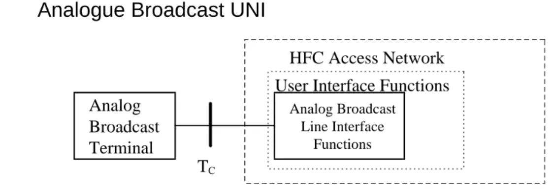
CFigure 5: Reference configuration at UNI for analogue broadcast
The Analogue Broadcast UNI is the interface between the HFC access network and a Broadcast terminal The Broadcast terminal is a Television Set, a Radio, or any equipment that is compatible to it (e.g. a Pay-TV decodingbox).
The Interface is situated at the TC reference point. ITU-T does not provide reference configurations for Broadcast access (although the N and J series provides Recommendations on sound and television matters).
With regard to basic functions , the Analogue Broadcast terminal is not different from an analogue Broadcast Terminal connected to a Broadcast distribution network in the same domain.
The Analogue Broadcast Physical interface is conform to CATV documents as defined by CENELEC.
7.1.1.1
Interface references
Standard Number Short titleEN 50083-1 Cabled distribution systems for television and sound signals - Part 1: Safety requirements EN 50083-2 Cabled distribution systems for television and sound signals - Part 2: Electromagnetic
compatibility for equipment
EN 50083-3 Cabled distribution systems for television and sound signals - Part 3: Active coaxial wideband distribution equipment
EN 50083-4 Cabled distribution systems for television and sound signals - Part 4: Passive coaxial wideband distribution equipment
EN 50083-5 Cabled distribution systems for television and sound signals - Part 5: Headend equipment EN 50083-6 Cabled distribution systems for television and sound signals - Part 6: Optical equipment EN 50083-7 Cabled distribution systems for television and sound signals - Part 7: System performance EN 50083-8 Cabled networks for television signals, sound signals and interactive services --Part 8:
Electromagnetic compatiblity for networks
EN 50083-9 Cable networks for television signals, sound and interactive services --Part 9: Interfaces for CATV/SMATV headends and similar equipment for DVB/MPEG-2 transport streams EN 50083-10 Cable networks for television signals, sound signals and interactive services -- Part 10: System
performance for return paths
7.1.1.2
Protocol stack reference
The following figure shows the stack architecture for the analogue cable TV interface. Functions performed by the analogue TV physical level are:
- analogue signal detection; - TV channel delineation.
Functions performed by the analogue TV channel level are: - synchronisation;
- video extraction; - sound extraction.
TV Channel level
Cable PMD level
Figure 6: Analogue TV stack
The analogue broadcast data is sent unidirectional from head end to the user. At the UNI the Digital TV stack level functions are performed from bottom to top of the stack. The analogue TV data signal is embedded in the HFC transport signal. No core functions nor user interface functions are necessary.
7.1.2
Digital Broadcast UNI
HFC Access Network
User Interface Functions
Digital
Broadcast
Terminal
Digital Broadcast Line Interface FunctionsT
CFigure 7: Reference configuration at UNI for digital broadcast
The Digital Broadcast UNI is the interface between the HFC access network and a Digital Broadcast terminal. The Digital Broadcast terminal is a Television Set, a Radio, or any equipment that is compatible to it (e.g. a Pay-TV decoding box).
The Interface is situated at the TC reference point. ITU-T does not provide reference configurations for Broadcast access (although the N series provides Recommendations on sound and television matters).
With regard to basic functions , the Digital Broadcast terminal is not different from a Digital Broadcast Terminal connected to a Digital Broadcast distribution network in the same domain.
The Digital Broadcast Physical interface is conform to ITU-T Recommendations J.83 and H.222.0 or ETS 300 429.
7.1.2.1
Interface references
Standard Number Short titleETS 300 429 Digital Video Broadcasting (DVB); Framing structure, channel coding and modulation for cable systems
J.83 Digital multiprogramme systems for television, sound and data services for cable distribution
H.222.0 Information technology – Generic coding of moving pictures and associated audio information: Systems
7.1.2.2
Protocol stack and peer communication stack reference
The following figure shows the stack architecture for the analogue cable TV interface. Functions performed by the MPEG-2 TS level are:- digital coding of video signal, audio signal and service signals; - video synchronisation.
Functions performed by the Reed Solomon level are: - generate error-protected data.
Functions performed by the Convolution interleaving level are: - interleaving data, resulting in interleaved frames. Functions performed by the Symbol/byte encoding level are:
Functions performed by the Differential encoding level are:
- assign coding points into a constellation diagram supporting differential encoding, so that the constellation is rotation invariant.
Functions performed by the QAM level are: - square \root raised cosine filtering; - QAM modulation/demodulation.
MPEG-2 TS level
Reed Solomon level
Convolutional interleaving level
Symbol/byte encoding level
Differential encoding level
QAM level
Cable PMD level
Figure 8: Digital TV stack
The digital broadcast data is sent unidirectional from head end to the user. At the UNI the Digital TV stack level functions are performed from bottom to top of the stack. The digital TV data signal under QAM format is embedded in the HFC transport signal.
7.2
PSTN UNI
HFC Access Network
User Interface Functions
POTS Cable Network Termination
POTS
Terminal
Z, T
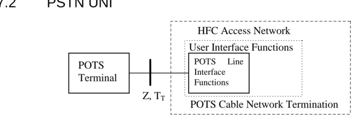
T POTS Line Interface FunctionsFigure 9: Reference configuration at UNI for POTS
The PSTN UNI is the interface between the HFC access network and the POTS (Plain Old Telephone Service) terminal. The POTS terminal is a POTS Telephone or any equipment that is compatible to it (fax, data modem, ...).
The Interface is situated at the Z (TT) reference point.
With regard to the basic telephony functions, the PSTN Terminal is not different from a PSTN Terminal connected to a PSTN in the same domain.
7.2.1
Interface references
Standard Number Short titleEN 300 001 Attachments to the Public Switched Telephone Network (PSTN); General technical requirements for equipment connected to an analogue subscriber interface in the PSTN
7.2.2
User Interface functions - POTS Cable Network Termination
The User interface functions for the POTS services over HFC Access network is fulfilled by a functional grouping called POTS Cable Network Termination. The POTS Cable Network Termination fulfils the interface between the digital exchange and analogue line terminal.
The functions related to control for an analogue subscriber line are related to ringing, supervision and signalling by means of line state changes, pulses, tones. These have to be communicated over the access network in some way. The pulses and changes of line state are interpreted by the POTS Network Termination. The tones are transparently passed over the access network and transferred to the local exchange; also reverse.
The network side of the POTS Cable Network Termination needs to sent out/receive the different signals related to POTS and to communicate the user voice (or other information) signal.
7.2.3
Protocol stack and peer communication stack reference
configuration
Protocol stacks are not applicable to analogue POTS lines. There is however a PSTN protocol for communication of the POTS signalling information over the V5 interface.
The PSTN protocol on the V5-interface is basically a stimulus protocol; i.e. it does not control the call procedures in the AN. It rather transfers information about the analogue line state over the V5-interface. The V5-PSTN protocol shall be used in conjunction with the national protocol entity in the LE. The national protocol entity in the LE, which is used for customer lines which are connected directly to the LE, will also be used to control calls on customer lines which are connected via the V5-interface. For time critical sequences it is also required to extract certain signalling sequences (e.g. compelled sequences) from the national protocol entity into an "AN part" of the national protocol entity. However, the V5-PSTN protocol has a relatively small functional part which is concerned with path set-up, release of the path on the V5-interface, call collision resolution on the V5-interface and handling of new calls in case of overload conditions in the LE. The majority of line signals will not be interpreted by the V5-PSTN protocol, but simply transferred transparently between the user port in the AN and national protocol entity in the LE.
Signalling information related to line state changes and pulses are handled via so-called Function Element (FE) groups, which are signals containing phone line information.
The LE shall be responsible for providing the service (call control, supplementary services). DTMF senders, receivers, tone generators and announcements shall be located in the LE. This implies that address information using DTMF shall be carried transparently between user port and LE whereas line state signalling shall be interpreted in the AN and then carried over the V5-interface by means of layer 3 messages.
It shall be the responsibility of the AN to handle access specific parameters related to the protocol such as recognition times of analogue signals, duration, voltage and frequency of meter pulses, ringing current or the specific details of a signalling sequence (AN part of the national protocol entity).
For time critical responses to customer signalling it is necessary for the AN to respond autonomously. This shall be explicitly required for ring trip and dial tone suppression. There may be other time critical responses required in national PSTN protocols which shall be defined in the national PSTN protocol mapping specification.
For time critical signalling sequences (e.g. autonomous seizure acknowledge for ground start PBXs) it shall also be necessary for the AN to control the time-critical part of the signalling sequence autonomously. In this case, the autonomous signalling sequence shall be triggered by the national protocol entity in the LE. After executing the autonomous signalling sequence, the AN may return a response to the LE.
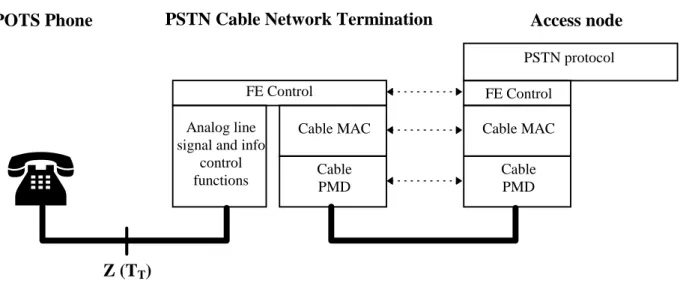
For the protocol peer configuration, some diagrams can be given. A first diagram is related to the control information, which is transferred over the cable network and used as a primitive for the V5 PSTN Protocol.
Access node
POTS Phone
PSTN Cable Network Termination
Z (T
T)
Analog line signal and info
control functions CablePMD Cable MAC Cable PMD FE Control FE Control Cable MAC PSTN protocol
Figure 10: Protocol peer configuration for POTS signalling
A second diagram is related to the user analogue signal and tones.
Access node
POTS Phone
POTS Cable Network Termination
Z (T
T)
Analog line info and tones
Cable PMD Cable MAC Cable PMD Cable MAC Modulation/demodulation 64kbit/s Channel 64kbit/s Channel A/D and D/A
conversion
Modulation/demodulation
Figure 11: Protocol peer configuration for POTS user info and tones
7.3
N-ISDN UNI
N-ISDN
Terminal
(N-TE), or
NT2
N-ISDN Line Interface FunctionsT, T
NHFC Access Network
User Interface Functions
N-ISDN Cable Network Termination
Figure 12: Reference configuration at UNI for N-ISDN
The N-ISDN UNI is the interface between the HFC access network and the N-ISDN terminal or NT2. The N-ISDN terminal is an N-TE terminal or any equipment that is compatible to it (possibly with Terminal Adapter).
The Interface is situated at the T (TN) reference point. The Reference configurations of ITU-T recommendation I.411 apply.
With regard to basic functions, the N-ISDN terminal is not different from a N-ISDN Terminal connected to a N-ISDN local exchange in the same domain (see reference [3]).
The N-ISDN Physical interface is described in the ITU-T Recommendations I.430 for the Basic Access (BA) and ITU-T Recommendation I.431 for the Primary Rate Access (PRA).
7.3.1
Interface references
Standard Number Short title
I.411 ISDN user-network interfaces – Reference configurations Q.921 ISDN user-network interface - Data link layer specification
Q.931 ISDN user-network interface layer 3specification for basic call control
7.3.1.1
Basic access
I.430 Basic user-network interface – Layer 1 specification
7.3.1.2
Primary access
I.431 Primary rate user-network interface – Layer 1 specification
7.3.2
User Interface functions - N-ISDN Cable Network Termination
The User interface functions for the N-ISDN services over HFC Access network is fulfilled by a functional grouping called N-ISDN Cable Network Termination. The N-ISDN Cable Network Termination fulfils the interface between the network and the N-ISDN TE or NT2.
The type of accesses supported for a single customer are the following:
- multipoint layer 1 passive bus configuration at the coincident S and T reference point; any N-ISDN teleservice or bearer service to be supported;
7.3.3
Protocol stack and peer communication stack reference
The protocol stacks for N-ISDN UNI, for basic and primary access are the following.Q.931 Network layer
OSI Layer stack
N-ISDN UNI BA stack
BA: Basic Access PRA: Primary Rate Access
Q.921
I.430 Physical layer
Data link layer
Q.931
N-ISDN UNI PRA stack
Q.921
I.431
Figure 13: Protocol stack at N-ISDN UNI at TN reference point
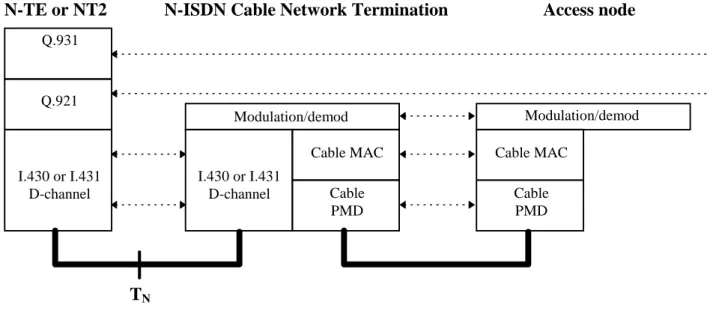
The peer communication stack configuration for signalling, from NT1 view, is given in the following figure. Signalling at layer 2 and layer 3 is not interpreted in the HFC access network.
Q.931
Access node
N-TE or NT2
N-ISDN Cable Network Termination
T
N I.430 or I.431 D-channel I.430 or I.431 D-channel Q.921 Cable PMD Modulation/demod Cable MAC Cable PMD Cable MAC Modulation/demodFigure 14: Protocol peer configuration for N-ISDN signalling
The peer communication stack configuration for B-channel info, from NT1 view, is given in the following figure. The information is transported over the access network to the telecommunication network.
Access node
N-TE or NT2
N-ISDN Cable Network Termination
T
N I.430 or I.431 B-channel I.430 or I.431 B-channel Cable PMD Modulation/demod B-channel info Cable MAC Cable PMD Cable MAC Modulation/demodFigure 15: Protocol peer configuration for N-ISDN user information
7.4
Internet Terminal UNI
HFC Access Network
User Interface Functions
IP Cable Network Term. Functions
Internet
Terminal
or IP LAN
Internet port FunctionsT
IFigure 16: Reference configuration at UNI for Internet
The Internet UNI at the TI reference point is the interface between the HFC access network and an Internet terminal. A Internet terminal is a PC or any other workstation or digital equipment that has external communication capability based on a (the) standard IP protocol and underlying layers.
The User Interface functions are practically realised by a device called "IP Cable Network Termination".
7.4.1
Interface references
Standard Number Short title
IETF RFC 894 IP Datagrams over Ethernet Networks
IETF RFC 1042 IP Datagrams over IEEE 802 Networks
IETF Internet-draft draft-ietf-ipcdn-ipcabledata-spec-00.txt
IP Over Cable Data Network service
ISO/IEC 10038 [7] (IEEE Std 802.1D) Information technology - Telecommunications and information exchange between systems - Local area networks - Media access control (MAC) bridges
ISO/IEC 8802-2 [8] Information technology - Telecommunications and information exchange between systems - Local and metropolitan area networks- Specific requirements - Part 2: Logical link control
ISO/IEC 8802-3 [9] Information technology - Telecommunications and information exchange between systems - Local and metropolitan area networks - Part 3: Carrier sense multiple access with collision detection (CSMA/CD) access method and physical layer specifications
ETS 300 429 Digital Video Broadcasting (DVB); Framing structure, channel coding and modulation for cable systems
ETS 300 800 Digital Video Broadcasting (DVB); Interaction channel for Cable TV distribution systems (CATV)
7.4.2
User interface functions - IP Cable Network Termination
The User interface functions for the IP data over HFC Access network is fulfilled by a functional grouping called IP Cable Network Termination. The IP Cable Network Termination used at the customer premises is called IP Cable Network Termination.
7.4.2.1
Definition
IP Cable Network TerminationA IP Cable Network Termination is a device that allows high-speed access to the Internet via a HFC access network. A IP Cable Network Termination will typically have two connections, one to the cable wall outlet to the network and the other to the Internet CPE equipment.
7.4.2.2
Functions and Technology
The IP Cable Network Termination technology provides an "always on" feature for individuals to have a high-speed access to the Internet.
IP Cable Network Termination capabilities vary widely.
In the downstream direction (from the network to the CPE), data rates can be anywhere up to 38,1 Mbit/s per 8 Mhz channel. Few terminals will be capable of connecting at such high data rates, so a more realistic number is 6 Mbit/s -9 Mbit/s.
In the upstream direction (from computer to network), data rates can be 3,088 Mbit/s, 1,544 Mbit/s or 256 kbit/s. In case of IP Cable Network Termination deployment, an asymmetric set-up will probably be more common than a symmetric set-up. In an asymmetric scheme, the downstream channel has a much higher bandwidth allocation (faster data rate) than the upstream. Current Internet applications tend to be asymmetric in nature. Activities such as World Wide Web navigating and newsgroup reading send much more data down to the computer than to the network. Image files and audio and video files are very bandwidth intensive in the downstream direction. Mouse clicks (URL requests) and e-mail messages are not bandwidth intensive in the upstream direction.
The fact that the word "modem" is used to describe this device can be a little misleading. Yes, it is a modem in the true sense of the word - it MOdulates and DEModulates signals. But the similarity ends there because IP Cable Network Terminations are more complicated than the traditional telephone modems. IP Cable Network Terminations can contain modem functions, but also tuner, encryption/decryption, medium access, and other functions.
Typically, a IP Cable Network Termination sends and receives data in two slightly different fashions.
- In the downstream direction, the digital data is modulated and then placed on a typical (e.g. 6 MHz to 8 MHz) television carrier, somewhere between 47 MHz and 860 MHz. There are several modulation schemes, but the two most popular are QPSK (up to ~10 Mbit/s) and QAM64 (up to ~36 Mbit/s). This signal can be placed in a channel adjacent to TV signals on either side without disturbing the cable television video signals.
- In a two-way activated cable network, the upstream (also known as the reverse path) is transmitted between 5 MHz and 65 MHz. The lower part of this bandwidth tends to be a noisy environment, with lots of interference from, e.g. CB radios and impulse noise from home appliances. Since cable networks are tree and branch
networks, all this noise gets added together as the signals travel upstream, combining and increasing (noise funnelling). Due to this problem, QPSK or a similar modulation scheme will be used in the upstream direction, because QPSK is more robust scheme than higher order modulation techniques in a noisy environment. QPSK is however "slower" than QAM.
7.4.3
Protocol stack and peer communication stack reference
The Internet IETF recommends multiple datalink/ physical link combinations on which the IP is able to run. A typical protocol stack is given in the following figure. Ethernet 10BaseT is a commonly used method.
RFC 1042/RFC 894 Internet Protocol (IP) Network layer
OSI Layer stack
Internet UNI at T
Istack
LLC: Logical Link Control MAC: Medium Access Control
ISO/IEC 8802.3 10BASE-T or 100 BASE-T
MAC sublayer
ISO/IEC 8802-2 LLC sublayer LLC sublaye
r
ISO/IEC 8802-3 MAC sublaye
r
Physical layer Data link layer
NOTE: Other options below the IP protocol are possible; when used, the underlying IP protocol stack needs to be replaced in all appropriate figures.
Figure 17: Protocol stack at Internet UNI on TI reference point
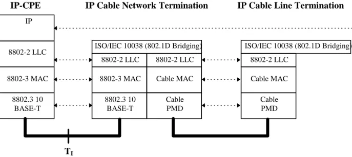
The peer communication stack configuration, from the IP Cable Network Termination viewpoint is given in the figure 18.
IP
IP-CPE
IP Cable Network Termination
IP Cable Line Termination
T
I 8802.3 10 BASE-T 8802-2 LLC 8802-3 MAC 8802.3 10 BASE-T 8802-2 LLC 8802-3 MAC Cable PMD ISO/IEC 10038 (802.1D Bridging) 8802-2 LLC Cable MAC Cable PMD Cable MAC 8802-2 LLC ISO/IEC 10038 (802.1D Bridging)7.5
Leased Lines UNI
Terminal
Leased Line Interface Functions * * Analogue or digitalT, T
LHFC Access Network
User Interface Functions
Leased Line Cable Network Termination *
Figure 19: Reference configuration at UNI for Leased Lines
The Leased line UNI is the interface between the HFC access network and a terminal or NT2. The terminal is any service terminal that is supported by the service network(s) that the HFC access network is serving.
The Interface is situated at the T (TL) reference point.
With regard to basic functions, the service terminal is not different from a same terminal directly connected to the corresponding service network.
There are a number of leased line interfaces standardised.
7.5.1
Interface references
Standard Number Short title
ETS 300 288 Business TeleCommunications (BTC); 64 kbit/s digital unrestricted leased line with octet integrity (D64U); Network interface presentation
ETS 300 418 Business TeleCommunications (BTC); 2 048 kbit/s digital unstructured and structured leased lines (D2048U and D2048S); Network interface presentation
ETS 300 448 Business TeleCommunications (BTC); Ordinary quality voice bandwidth 2-wire analogue leased line (A2O); Connection characteristics and network interface presentation
ETS 300 449 Business TeleCommunications (BTC); Special quality voice bandwidth 2-wire analogue leased line (A2S); Connection characteristics and network interface presentation
ETS 300 451 Business Telecommunications (BTC); Ordinary quality voice bandwidth 4-wire analogue leased line (A4O); Connection characteristics and network interface presentation
ETS 300 452 Business Telecommunications (BTC); Special quality voice bandwidth 4-wire analogue leased line (A4S); Connection characteristics and network interface presentation
ETS 300 766 Business TeleCommunications (BTC); Multiple 64 kbit/s digital unrestricted leased lines with octet integrity presented at a structured 2 048 kbit/s interface at either or both ends (D64M); Connection characteristics and network interface presentation
ETS 300 686 Business TeleCommunications (BTC); 34 Mbit/s and 140 Mbit/s digital leased lines (D34U, D34S, D140U and D140S); Network interface presentation
ETS 300 687 Business TeleCommunications (BTC); 34 Mbit/s digital leased lines (D34U and D34S); Connection characteristics
ETS 300 688 Business TeleCommunications (BTC); 140 Mbit/s digital leased lines (D140U and D140S); Connection characteristics
ETS 300 689 Business TeleCommunications (BTC); 34 Mbit/s digital leased lines (D34U and D34S); Terminal equipment interface
ETS 300 690 Business TeleCommunications (BTC); 140 Mbit/s digital leased lines (D140U and D140S); Terminal equipment interface
TBR 25 Business TeleCommunications (BTC); 140 Mbit/s digital unstructured and structured leased lines (D140U and D140S); Attachment requirements for terminal equipment interface
7.5.2
User Interface functions - Leased Cable Network Termination
The User interface functions for the leased line services over HFC Access network is fulfilled by a functional group called Leased line Cable Network Termination. The leased line Cable Network Termination fulfils the interface between the network and the User plane functions of TE. Signalling is not an issue.
Leased line user interface functions are limited to core functions.
7.5.3
Protocol stack and peer communication stack reference
This is depending upon the service offered. User information is modulated/demodulated and handled via the Cable MAC function and the cable PMD function transmitted over the HFC transport network, or reverse.
8
Service Node Interfaces (SNI) (Access Node
Interface)
8.1
Broadcast Service
Head End
Broadcast Service
Broadcast Ser-vice Interface FunctionsP
Cor M
CFigure 20: Reference configuration at SNI for Broadcast
This interface has no typical access network interfaces. The interface is identical to the interface on TC. The interface can be analogue, but may support digital coded information.
8.2
PSTN Service specific Service node
A service specific service node is only dedicated to one single service (ITU-T Recommendation G.902). In this case the interface is dedicated to PSTN.
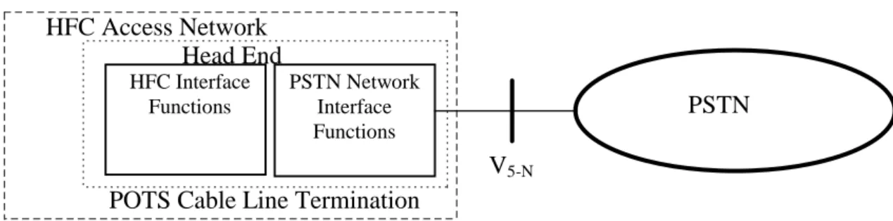
POTS Cable Line Termination
HFC Access Network
Head End
PSTN
HFC Interface Functions PSTN Network Interface FunctionsV
5-NFigure 21: Reference configuration at SNI for PSTN
The V5.1-N interface consists of a 2 048 kbit/s interface as defined in ETS 300 166 and ETS 300 167. The V5.2-N interface may have between 1 and 16 2048 kbit/s interface links.
Descriptions to be found in ETS 300 324 for V5.1-N and in ETS 300 347 for V5.2-N.
8.2.1
Interface references
Standard Number Short title
G.964 [5] / ETS 300 324 V5.1 Interface G.965 [6] / ETS 300 347 V5.2 Interface
8.2.2
Network interface functions - PSTN Cable Line Termination
The Network interface functions for the PSTN information over HFC Access network is fulfilled by a functional grouping called PSTN Cable Line Termination. The PSTN Cable Line Termination is located at the Head End.
8.2.3
Protocol stack and peer communication stack reference
configurations
8.2.3.1
Protocol stacks
8.2.3.1.1
V5.1
Ninterface
The following figure shows the protocol architecture for the V5.1 interface. The functions performed are defined as follows (more information can be obtained in the V5.1 recommendation).
- Envelope function sublayer of LAPV5 (LAPV5-EF). - Data link sublayer of LAPV5 (LAPV5-DL).
- Sublayer-to-sublayer communication and mapping function. - PSTN signalling protocol specification and layer 3 multiplexing. - Control protocol.
Stack at Local Exchange
OSI
Stack at AN side
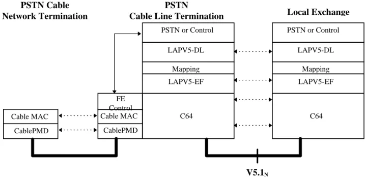
Mapping LAPV5-EF C64 LAPV5-DL Mapping LAPV5-EF C64 PSTN LAPV5-DL Network layer Physical layer Data link layer Control PSTN Control
Figure 22: Protocol stacks for V5.1N for PSTN
8.2.3.1.2
V5.2
Ninterface
The following figure shows the protocol architecture for the V5.2 interface. The functions performed are defined as follows (more information can be obtained in the V5.2 recommendation):
- envelope function sublayer of LAPV5 (LAPV5-EF); - data link sublayer of LAPV5 (LAPV5-DL);
- sublayer-to-sublayer communication and mapping function; - general layer 3 protocol structures;
- PSTN signalling protocol specification; - control protocol;
- link control protocol; - BCC protocol; - protection protocol.
Stack at Local Exchange
OSI
Stack at AN side
Mapping LAPV5-EF C64 PSTN LAPV5-DL Network layer Physical layer Data link layer Prot. Port/ link Contr. BCC Mapping LAPV5-EF C64 PSTN LAPV5-DL Prot. Port/ link Contr. BCC
Figure 23: Protocol stacks for V5.2N
8.2.3.2
Protocol peer configurations
Local Exchang
PSTN
Cable Line Termination
PSTN Cable
Network Termination
V5
N CablePMD Cable MAC 64kbit/s Channel CablePMD Cable MAC C64 C64 Modulation/demod. Modulation/demod.Figure 24: Protocol peer configuration for POTS User information
8.2.3.2.1
V5.1 interface
The following figures show different Protocol peer stack configurations for different contexts.