Summit Switch
Installation and User
Guide
Copyright © Extreme Networks, Inc., 1997. All rights reserved. No part of this documentation may be reproduced in any form or by any means or used to make any derivative work (such as translation, transformation, or adaptation) without permission from Extreme Networks, Inc.
Extreme Networks, ExtremeWare, Summit, and the Extreme Networks logo are trademarks of Extreme Networks.
All other brand and product names are registered trademarks or trademarks of their respective holders.
P
REFACE
This preface provides an overview of this guide, describes guide conventions, tells you where to look for speciÞc information and lists other publications that may be useful.
I
NTRODUCTION
This guide provides the required information to install and conÞgure the Summit1 and Summit2 Gigabit Ethernet Switch.
This guide is intended for use by network administrators who are responsible for installing and setting up network equipment. It assumes a basic working knowledge of
¥ Local Area Networks (LANs)
¥ Ethernet concepts
¥ Ethernet switching and bridging concepts
¥ Simple Network Management Protocol (SNMP)
If the information in the Release Notes shipped with your Switch differs from the information in this guide, follow the Release Notes.
Explanations about features and operations that are the same among all members of the Summit family simply refer to the product as the Summit.
C
ONVENTIONS
Table 1 and Table 2 list conventions that are used throughout this guide.
Table 1: Notice Icons
Icon Notice Type Alerts you to...
Note Important features or instructions.
Caution Risk of personal injury, system damage, or loss of data.
Warning Risk of severe personal injury.
Table 2: Text Conventions
Convention Description
Screen displays This typeface represents information as it appears on the screen.
The words “enter” and “type”
When you see the word “enter” in this guide, you must type
something, and then press the Return or Enter key. Do not press the Return or Enter key when an instruction simply says “type.”
[Key] names Key names appear in text in one of two ways:
■ Referred to by their labels, such as “the Return key” or “the Escape key”
■ Written with brackets, such as [Return] or [Esc]
If you must press two or more keys simultaneously, the key names are linked with a plus sign (+). Example:
Press [Ctrl]+[Alt]+[Del].
Words in italicized type Italics emphasize a point or denote new terms at the place where they are defined in the text.
RELATED PUBLICATIONS
The command syntax is explained in Chapter 4.
R
ELATED
P
UBLICATIONS
The Summit documentation set includes the following:
¥ Summit Quick Reference Guide
¥ Summit Release Note
You may Þnd the following Web site of interest:
¥ Extreme Networks Home Page: http://www.extremenetworks.com/ SUMMIT.BK Page iii Thursday, September 25, 1997 12:33 PM
1
Summit Overview
This chapter describes the following:
¥ Summit1 and Summit2 features
¥ How to use the Summit family of switches in your network conÞguration
¥ Summit front views
¥ Summit rear view
¥ Factory default settings
A
BOUT
THE
S
UMMIT
F
AMILY
OF
S
WITCHES
Network managers are currently faced with the challenge of creating networks that can provide ultra-fast speed and high performance to serve the needs of todayÕs network users, while simultaneously preserving the investment they have made in Ethernet and Fast Ethernet technology.
By addressing the entire spectrum of Ethernet data rates (10/100/1000 Mbps), the Summit family of LAN switches enables you to introduce high-speed Gigabit Ethernet backbones into your existing network, while maintaining established connections to the 10 Mbps and 100 Mbps segments that already exist.
SUMMIT OVERVIEW
S
UMMARY
OF
F
EATURES
The Summit family of switches is comprised of two models: the Summit1 and the Summit2.
Both switches have the following features:
¥ Support for 128K addresses in the Switch forwarding database
¥ Fully nonblocking operation
Ñ All ports transmit and receive packets at wire speed
¥ Autonegotiation for half- or full-duplex operation
¥ Optional redundant power supply
¥ Redundant physical Gigabit Ethernet backbone connection
¥ Virtual local area networks (VLANs) including support for 802.1Q
¥ Quality of Service (QoS)
¥ Spanning Tree Protocol (STP) (IEEE 802.1D) with multiple STP domains
¥ Wirespeed Internet Protocol (IP) routing via Routing Information Protocol (RIP) version 1 and RIP version 2
¥ Integrated network management
¥ Console connection
¥ Telnet connection
¥ Web interface
¥ Simple Network Management Protocol (SNMP) support
P
ORTC
ONNECTIONSThe Summit1 provides eight Gigabit Ethernet ports. Six of the ports are Þxed
1000Base-SX ports using 850nm duplex SC connectors. Two of the ports are modular, and support the standard Gigabit Interface Connector (GBIC). This enables you to select various types of Þber and copper modules to support longer distances or lower cost. The Summit1 can be ordered with either two 1000Base-SX or two 1000Base-LX GBIC transceivers already installed. GBIC transceivers can also be ordered separately.
SUMMARYOF FEATURES
Figure 1-1 shows the front view of the Summit1.
Figure 1-1: Summit1 front view
The Summit2 is a workgroup switch featuring sixteen 10Base-T/100Base-TX ports, two Gigabit Ethernet uplinks, and one redundant Gigabit Ethernet uplink. The
10Base-T/100Base-TX ports use standard RJ-45 connectors. They are autosensing for 10/100 Mbps operation, as well as half- or full-duplex operation. The Gigabit Ethernet interfaces support the GBIC connector, and ship with standard 1000Base-SX, 850nm GBIC modules. Additional cable types are also supported.
Figure 1-2 shows the front view of the Summit2 Port status LEDs
Gigabit Ethernet ports
Unit status LEDs
Gigabit Ethernet ports
Port status LEDs Unit status LEDs SUMMIT.BK Page 3 Thursday, September 25, 1997 12:33 PM
F
ULL-
DUPLEXThe Summit Switch provides full-duplex support for all ports. Full-duplex allows frames to be transmitted and received simultaneously and, in effect, doubles the bandwidth available on a link. All 10/100 Mbps ports on the Summit autonegotiate for half- or full-duplex operation.
P
ORTR
EDUNDANCYThe Summit2 has an optional redundant Gigabit Ethernet port. Using the redundant port, you can dual-home the Summit2 to one or two Switches. Figure 1-3 illustrates a Summit2 dual-homed to two different Switches.
Figure 1-3: Dual-homing configuration
In the event that the active port fails or loses link status, the redundant port is
automatically activated. When the primary port resumes operation, the redundant port becomes inactive. The redundant port cannot be used for load sharing.
V
IRTUALLAN
S(VLAN
S)
The Summit has a VLAN feature that enables you to construct your broadcast domains without being restricted by physical connections. Up to 255 VLANs can be deÞned on the Summit. A VLAN is a group of location- and topology-independent devices that communicate as if they were on the same physical local area network (LAN). Implementing VLANs on your network has the following three advantages:
Dual-homed
SUMMARYOF FEATURES
¥ It helps to control broadcast trafÞc. If a device in VLAN marketing transmits a broadcast frame, only VLAN marketing devices receive the frame.
¥ It provides extra security. Devices in VLAN marketing can only communicate with devices on VLAN sales using a device that provides routing services.
¥ It eases the change and movement of devices on networks. If a device in VLAN marketing is moved to a port in another part of the network, all you must do is specify that the new port belongs to VLAN marketing.
For more information on VLANs, refer to Chapter 5.
S
PANNINGT
REEP
ROTOCOL (STP)The Summit supports the IEEE 802.1D Spanning Tree Protocol (STP), which is a
bridge-based mechanism for providing fault tolerance on networks. STP enables you to implement parallel paths for network trafÞc, and ensure the following:
¥ Redundant paths are disabled when the main paths are operational.
¥ Redundant paths are enabled if the main trafÞc paths fail. The Summit supports up to 64 Spanning Tree Domains (STPDs).
For more information on STP, refer to Chapter 7.
Q
UALITY OFS
ERVICE(Q
OS)
The Summit has Quality of Service (QoS) features that enable you to specify service levels for different trafÞc groups. By default, all trafÞc is assigned with the ÒnormalÓ QoS proÞle. If needed, you can conÞgure some trafÞc to have different guaranteed minimum bandwidth, maximum bandwidth, and priority.
IP U
NICASTR
OUTINGThe Summit can route IP trafÞc between the VLANs that are conÞgured as virtual router interfaces. Both dynamic and static IP routes are maintained in the routing table. RIP version 1 and RIP version 2 are supported.
For more information on IP unicast routing, see Chapter 9.
N
ETWORK
C
ONFIGURATION
E
XAMPLES
This section describes where to position the Summit1 and Summit2 within your network.
One common use of the Summit is on a Gigabit Ethernet backbone. Figure 1-4 shows an example of a Gigabit Ethernet backbone within a building.
NETWORK CONFIGURATION EXAMPLES
Figure 1-4: Summit family used in a backbone configuration
The Summit2 on each ßoor is connected to the backbone Summit1 using a 1 Gbps, full-duplex link. Using Gigabit Ethernet as a backbone technology removes bottlenecks by providing scalable bandwidth, low-latency, high-speed data switching.
Internet Workstations
Workgroup hubs Regional wiring closet
Regional wiring closet
Gigabit Ethernet risers
Power workgroup
Backbone
PCs
1st floor
2nd floor
3rd floor
4th floor
Workgroup switches
PCs
Router
Meshed campus backbone
Another common use for the Summit family is in a campus environment, as shown in
Figure 1-5.
Figure 1-5: Summit family used in a campus environment
The Summit1 switches located in each building form a meshed backbone, providing load balancing and redundancy. In addition, the Summit2 Switch in Building 2 is dual-homed to the Summit1 located in Building 1 and to the Summit1 located in Building 2.
Intranet/Internet
Dual-homing
Workstations PCs
Load-balanced
links
Meshed
backbone
Building 3
Building 2
SUMMIT1 FRONT VIEW
S
UMMIT
1 F
RONT
V
IEW
Figure 1-6 shows the Summit1 front view.
Figure 1-6: Summit1 front view
P
ORTSThe Summit1 has eight Gigabit Ethernet ports. Six of the ports use SC connectors and support 1000Base-SX over 850nm Þber-optic cable. Ports 1 and 8 have GBIC connectors and support the media types and distances listed in Table 1-1.
For more information on 1000Base-SX and 1000Base-LX link characteristics, refer to IEEE Draft P802.3z/D3.1, Table 38-8.
Table 1-1: Summit1 Supported Media Distances for GBIC Connectors
Distance Gigabyte Type
50/125 micro Multimode Fiber
62.5/125 micron
Multimode Fiber Single-mode Fiber
850nm Multimode Optics
1300nm
Single-mode Optics
550 Meters
550 Meters
260 Meters
440 Meters
Not supported
3000 Meters Port status LEDs
Gigabit Ethernet ports
Unit status LEDs
LED
STable 1-2 describes the light emitting diode (LED) behavior on the Summit1.
Table 1-2: Summit1 LEDs
LED Color Indicates
Power Green Yellow
The Summit1 is powered up.
The Summit1 is indicating a power, overheat, or fan failure. MGMT Green flashing
■ Slow ■ Medium ■ Fast Yellow
■ Power On Self Test (POST) in progress. ■ The Summit1 is operating normally. ■ Software download in progress. The Summit1 has failed its POST.
Port Status LEDs
Packet Yellow Off
Frames are being transmitted/received on this port. No activity on this port.
Status Green on Green flashing Off
Link is present; port is enabled; full-duplex operation.
Link is present; port is disabled. Link is not present.
SUMMIT2 FRONT VIEW
S
UMMIT
2 F
RONT
V
IEW
Figure 1-7 shows the Summit2 front view.
Figure 1-7: Summit2 front view
P
ORTSThe Summit2 has 16 autosensing 10Base-T/100Base-TX ports, two Gigabit Ethernet ports, one of which has a redundant Gigabit Ethernet port. Table 1-3 describes the ports, connectors, media, and maximum distances for each port type.
Table 1-3: Summit2 Supported Media
Media Module (Ports) Connector Media
Maximum Distance
RJ-45 RJ-45 Category 5 Cable (at 100Mbps)
Category 3 Cable (at 10Mbps)
100 Meters
850nm Multimode Optics SC 50u/125 Multimode Fiber 62.5u/125 Multimode Fiber
550 Meters 260 Meters 1300nm Singlemode Optics SC 50u/125 Multimode Fiber
62.5u/125 Multimode Fiber 10u Singlemode Fiber
550 Meters 440 Meters 3000 Meters Port status LEDs
10/100 Mbps ports
Unit status LEDs
LED
STable 1-4 describes the LED behavior on the Summit2.
Table 1-4: Summit2 LEDs
LED Color Indicates
Power Green
Yellow
The Summit2 is powered up.
The Summit2 is indicating a power, overheat, or fan failure. MGMT Green flashing
■ Slow ■ Medium ■ Fast Yellow
■ Power On Self Test (POST) in progress. ■ The Summit2 is operating normally. ■ Software download in progress. The Summit2 has failed its POST.
10/100Mbps Port Status LEDs
Green Yellow Green flashing Off
Link is present; port is enabled.
Frames are being transmitted/received on this port. Link is present; port is disabled.
Link is not present.
Gigabit Ethernet Port Status LEDs
Packet Yellow Off
Frames are being transmitted/received on this port. No activity on this port.
Status Green on Green flashing Off
Link is present; port is enabled; full-duplex operation.
Link is present; port is disabled. Link is not present.
SUMMIT REAR VIEW
S
UMMIT
R
EAR
V
IEW
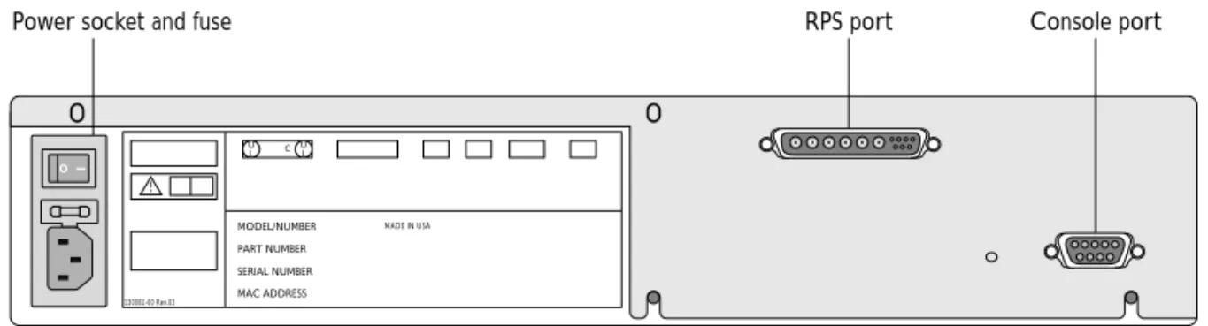
Figure 1-8 shows the rear view for the Summit1 and the Summit2.
Figure 1-8: Summit rear view
P
OWERS
OCKETThe Summit automatically adjusts to the supply voltage. The power supply operates down to 90 V. The fuse is suitable for both 110 V AC and 220-240 V AC operation.
S
ERIALN
UMBERYou may need this serial number for fault-reporting purposes.
C
ONSOLEP
ORTUse the console port (9-pin, ÒDÓ type connector) for connecting a terminal and carrying out local out-of-band management.
R
EDUNDANTP
OWERS
UPPLYP
ORTThe redundant power supply (RPS) port is used to connect to a Summit RPS. The Summit RPS provides a redundant power source to the Summit. If the primary power source for the Switch fails, the Summit RPS takes over, ensuring uninterrupted network operation.
130001-00 Rev.03
C
MADE IN USA U
L U L
!
SERIAL NUMBER MAC ADDRESS PART NUMBER MODEL/NUMBER
Console port RPS port
MAC A
DDRESSThis label shows the unique Ethernet MAC address assigned to this device.
F
ACTORY
D
EFAULTS
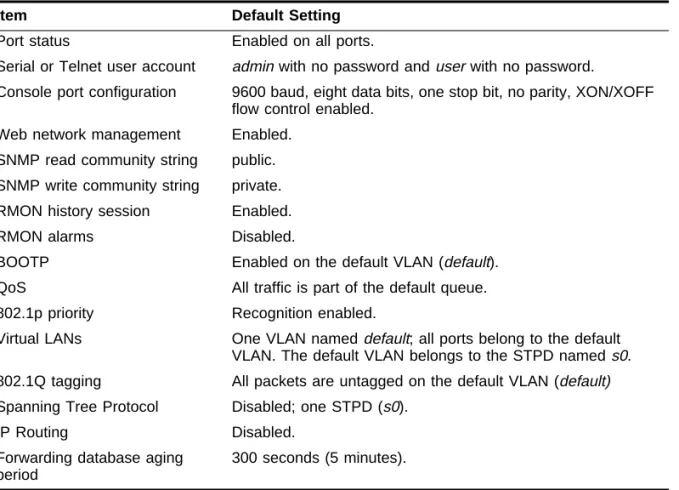
Table 1-5 shows factory defaults for the Summit features.
Table 1-5: Summit Factory Defaults
Item Default Setting
Port status Enabled on all ports.
Serial or Telnet user account admin with no password and user with no password.
Console port configuration 9600 baud, eight data bits, one stop bit, no parity, XON/XOFF flow control enabled.
Web network management Enabled. SNMP read community string public. SNMP write community string private. RMON history session Enabled.
RMON alarms Disabled.
BOOTP Enabled on the default VLAN (default). QoS All traffic is part of the default queue. 802.1p priority Recognition enabled.
Virtual LANs One VLAN named default; all ports belong to the default VLAN. The default VLAN belongs to the STPD named s0. 802.1Q tagging All packets are untagged on the default VLAN (default) Spanning Tree Protocol Disabled; one STPD (s0).
IP Routing Disabled.
Forwarding database aging period
2
Installation and Setup
This chapter describes the following:
¥ How to decide where to install the Summit
¥ Gigabit Ethernet conÞguration rules
¥ How to install the Switch in a rack or free-standing
¥ How to connect equipment to the console port
¥ How to check the installation using the Power On Self-Test (POST)
F
OLLOWING
S
AFETY
I
NFORMATION
Before installing or removing any components of the Switch, or before carrying out any maintenance procedures, you must read the safety information provided in Appendix A
of this guide.
D
ETERMINING
THE
S
WITCH
L
OCATION
The Summit is suited for use in the ofÞce, where it can be free-standing or mounted in a standard 19-inch equipment rack. Alternatively, the device can be rack-mounted in a
When deciding where to install the Switch, ensure that:
¥ The Switch is accessible and cables can be connected easily.
¥ Water or moisture cannot enter the case of the unit.
¥ Air-ßow around the unit and through the vents in the side of the case is not restricted. You should provide a minimum of 25mm (1-inch) clearance.
¥ No objects are placed on top of the unit.
¥ Units are not stacked more than four high if the Switch is free-standing.
C
ONFIGURATIONR
ULESThe connectors, supported media types, and maximum distances for the Summit family are described in Chapter 1.
I
NSTALLING
THE
S
UMMIT
The Summit can be mounted in a rack, or placed free-standing on a tabletop.
R
ACKM
OUNTINGThe Switch is 2U high and will Þt in most standard 19-inch racks.
The rack mount kits must not be used to suspend the Switch from under a table or desk, or attach it to a wall.
To rack mount the Summit, follow these steps:
1 Place the Switch the right way up on a hard ßat surface, with the front facing toward you.
2 Remove the existing screws from the sides of the chassis and retain for Step 4.
3 Locate a mounting bracket over the mounting holes on one side of the unit.
4 Insert the four screws and fully tighten with a suitable screwdriver, as shown in
INSTALLINGTHE SUMMIT
Figure 2-1: Fitting the mounting bracket
5 Repeat the three previous steps for the other side of the Switch.
6 Insert the Switch into the 19-inch rack and secure with suitable screws (not provided). Ensure that ventilation holes are not obstructed.
7 Connect the Summit to the redundant power supply (if applicable).
8 Connect cables.
F
REE-S
TANDINGThe Summit is supplied with four self-adhesive rubber pads. Apply the pads to the underside of the device by sticking a pad in the marked area at each corner of the Switch.
S
TACKING THES
WITCH ANDO
THERD
EVICESUp to four units can be placed on top of one another.
This section relates only to physically placing the devices on top of one another. The Switch does not form a stack (that is, a number of devices linked together
C
ONNECTING
E
QUIPMENT
TO
THE
C
ONSOLE
P
ORT
Connection to the console port is used for direct local management. The Switch console port settings are set as follows:
¥ Baud rate Ñ 9600
¥ Data bits Ñ 8
¥ Stop bit Ñ 1
¥ Parity Ñ None
¥ Flow control Ñ XON/XOFF
The terminal connected to the console port on the Switch must be conÞgured with the same settings. This procedure will be described in the documentation supplied with the terminal.
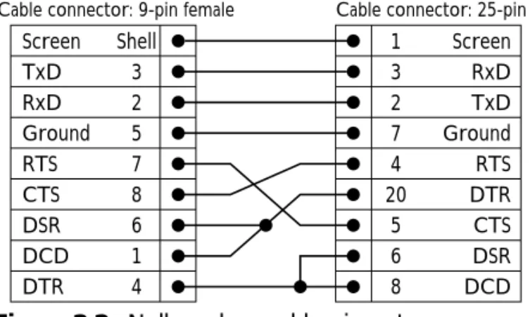
Appropriate cables are available from your local supplier. In order to make your own cables, pin-outs for a DB-9 male console connector are described in Table 2-1.
Figure 2-2 shows the pin-outs for a 9-pin to RS-232 25-pin null-modem cable.
Figure 2-2: Null-modem cable pin-outs Table 2-1: Console Connector Pin-Outs
Function Pin Number
TXD (transmit data) 3 RXD (receive data) 2
GND (ground) 5
Screen TxD RxD Ground RTS CTS DSR DCD DTR
Cable connector: 9-pin female
Summit
Cable connector: 25-pin male/female
PC/Terminal Screen RxD TxD Ground RTS DTR CTS DSR DCD Shell 3 2 5 7 8 6 1 4 1 3 2 7 4 20 5 6 8
POWERING-UPTHE SWITCH
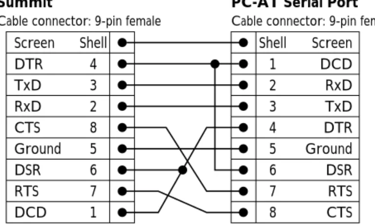
Figure 2-3 shows the pin-outs for a 9-pin to 9-pin PC-AT null-modem serial cable.
Figure 2-3: PC-AT serial null-modem cable pin-outs
P
OWERING
-
UP
THE
S
WITCH
To turn on power to the Switch, connect the power cable to the Switch and then to the wall outlet, and turn the on/off switch to the on position.
C
HECKING
THE
I
NSTALLATION
After turning on power to the Summit, the device performs a Power On Self-Test (POST).
During the POST, all ports are temporarily disabled, the packet LED is off, the power LED is on, and the MGMT LED ßashes. The MGMT LED ßashes until the Switch has successfully passed the POST.
If the Switch passes the POST, the MGMT LED blinks at a slow rate (1 blink per second). If the Switch fails the POST, the MGMT LED shows a solid yellow light.
For more information on the LEDs, refer to Table 1-2 and Table 1-4.
Screen DTR TxD RxD CTS Ground DSR RTS DCD
Cable connector: 9-pin female
Summit
Cable connector: 9-pin female
PC-AT Serial Port
Screen DCD RxD TxD DTR Ground DSR RTS CTS Shell 4 3 2 8 5 6 7 1 Shell 1 2 3 4 5 6 7 8
LOGGING
IN
FOR
THE
F
IRST
T
IME
After the Summit has completed the POST, it is operational. Once operational, you can log in to the Switch and conÞgure an IP address for the default VLAN (named default). To manually conÞgure the IP settings, perform the following steps:
1 Connect a terminal or workstation running terminal-emulation software to the console port.
2 At your terminal, press [Return] one or more times until you see the login prompt.
3 At the login prompt, enter the default user name admin to log on with administrator privileges. For example:
login: admin
Administrator capabilities allow you to access all Switch functions. For more information on Switch security, refer to Chapter 3.
4 At the password prompt, press [Return].
The default name, admin, has no password assigned. When you have successfully logged on to the Switch, the command-line prompt displays the name of the Switch in its prompt.
5 Assign an IP address and subnetwork mask for VLAN default by typing config vlan default ipaddress 123.45.67.8 255.255.255.0 Your changes take effect immediately.
6 Save your conÞguration changes so that they will be in effect after the next Switch reboot, by typing
save
For more information on saving configuration changes, refer to Chapter 11.
7 When you are Þnished using the facility, logout of the Switch by typing logout
After two incorrect login attempts, the Summit locks you out of the login facility. You must wait a few minutes before attempting to log in again.
3
Accessing The Switch
This chapter provides the following required information to begin managing the Summit:
¥ ConÞguring the Switch for management
¥ Switch management methods
¥ ConÞguring SNMP
¥ ConÞguring Switch ports
In order for configuration changes to be retained through a Switch power cycle or reboot, you must issue a SAVE command after you have made the change. For more information on the SAVE command, refer to Chapter 11.
C
ONFIGURING
M
ANAGEMENT
A
CCESS
The Summit supports the following two level levels of management:
¥ User
¥ Administrator
A user-level account can use the ping command to test device reachability, and change
the password assigned to the account name. If you have logged on with user capabilities, the command-line prompt will end with a (>) sign. For example:
Summit1:2>
An administrator-level account can view and change all Switch parameters. It can also add and delete users, and change the password associated with any account name. The administrator can disconnect a management session that has been established by way of a Telnet connection. If this happens, the user logged on by way of the Telnet connection is notiÞed that the session has been terminated.
If you have logged on with administrator capabilities, the command-line prompt will end with a (#) sign. For example:
Summit1:18#
The prompt text is taken from the SNMP sysname setting. The number that follows the colon indicates the sequential line/command number.
If an asterisk (*) appears in front of the command-line prompt, it indicates that you have outstanding conÞguration changes that have not been saved. For example:
*Summit1:19#
For more information on saving configuration changes, refer to Chapter 11.
D
EFAULTA
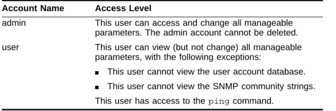
CCOUNTSBy default, the Switch is conÞgured with two accounts, as shown in Table 3-1.
Table 3-1: Default Accounts
Account Name Access Level
admin This user can access and change all manageable parameters. The admin account cannot be deleted. user This user can view (but not change) all manageable
parameters, with the following exceptions:
■ This user cannot view the user account database. ■ This user cannot view the SNMP community strings. This user has access to the ping command.
CONFIGURING MANAGEMENT ACCESS
CHANGINGTHE DEFAULT PASSWORD
Default accounts do not have passwords assigned to them. Passwords must have a minimum of 4 characters and can have a maximum of 12 characters.
Passwords are case-sensitive.
To add a password to the default admin account, follow these steps:
1 Log in to the Switch using the name admin.
2 At the password prompt, press [Return].
3 Add a default admin password by typing the following: config account admin
4 Enter the new password at the prompt.
5 Re-enter the new password at the prompt.
To add a password to the default user account, follow these steps:
1 Log in to the Switch using the name admin.
2 At the password prompt, press [Return].
3 Add a default user password by typing the following: config account user
4 Enter the new password at the prompt.
5 Re-enter the new password at the prompt.
If you forget your password while logged out of the command-line interface, contact your local technical support representative, who will advise on your next course of action.
C
REATING AM
ANAGEMENTA
CCOUNTThe Switch can have a total of three management accounts. You can use the default names (admin and user), or you can create new names and passwords for the accounts. Passwords must have a minimum of 4 characters and can have a maximum of 12
To create a new account, follow these steps:
1 Log in to the Switch as admin.
2 At the password prompt, press [Return].
3 Add a new user by using the following command:
create account [admin | user] <username>
4 Enter the password at the prompt.
5 Re-enter the password at the prompt.
VIEWING SWITCH ACCOUNTS
To view the accounts that have been created, you must have administrator privileges. Enter the following to see the accounts:
show account
Output from the show accounts command is as follows:
#show accounts
User Name Access LoginOK Failed Session --- --- --- --- admin R/W 0 0
user RO 0 0
DELETINGA SWITCH ACCOUNT
To delete a Switch account, you must have administrator privileges. Use the following command to delete an account:
delete account <username>
M
ETHODS
OF
M
ANAGING
THE
S
UMMIT
You can manage the Summit using the following methods:¥ Access the command-line interface by connecting a terminal (or workstation with terminal-emulation software) to the Summit console port.
¥ Access the command-line interface over a TCP/IP network using a Telnet connection.
USING TELNET
¥ Access the Web interface over a TCP/IP network, using a standard Web browser (such as Netscape Navigatorª 3.0 or greater, or Microsoft Internet Explorerª 3.0 or greater).
¥ Use an SNMP Network Manager over a network running the IP protocol.
The Switch can support up to four user sessions concurrently (for example, one console port, one Web session, and two Telnet connections).
U
SING THEC
ONSOLEI
NTERFACEThe command-line interface built into the Switch is accessible by way of the 9-pin, RS-232 console port located on the rear of the unit.
For more information on the console port pin-outs, refer to Chapter 2.
Once the connection is established, you will see the system prompt and you may log in.
U
SING
T
ELNET
Any workstation with a Telnet facility should be able to communicate with the Switch over a TCP/IP network. Up to three active Telnet sessions can access the Switch concurrently. The Telnet connection will time out after three minutes of inactivity. If a connection to a Telnet session is lost inadvertently, the Switch terminates the session within three minutes.
Before you can start a Telnet session, you must set up the IP parameters described in the section ÒConÞguring Switch IP Parameters,Ó later in this chapter. Telnet is enabled by default.
To open the Telnet session, you must specify the IP address of the device that you want to manage. Check the user manual supplied with the Telnet facility if you are unsure of how to do this.
USINGA BOOTP SERVER
If you are using IP and you have a BOOTP server set up correctly on your network, you must add the following information to the BOOTP server:
¥ Switch Media Access Control (MAC) address
¥ IP address
¥ Subnet address mask (optional)
¥ Default gateway
The Switch MAC address is found on the rear label of the Switch.
Once this is done, the IP address, subnetwork mask, and default gateway for the Switch will be downloaded automatically. You can then start managing the Switch without further conÞguration.
You can enable BOOTP on a per-VLAN basis by using the following command:
enable bootp vlan [<name> | all]
By default, BOOTP is enabled on the default VLAN.
MANUALLY CONFIGURINGTHE IP SETTINGS
If you are using IP without a BOOTP server, you must enter the IP parameters for the Switch in order for the SNMP Network Manager or Telnet software to communicate with the device. To assign IP parameters to the Switch, you must do the following:
¥ Log in to the Switch with administrator privileges.
¥ Assign an IP address and subnetwork mask to a VLAN.
The Switch comes conÞgured with a default VLAN named default. To use Telnet or an SNMP Network Manager, you must have at least one VLAN on the Switch, and it must be assigned an IP address and subnetwork mask. IP addresses are always assigned to a VLAN. The Summit can be assigned multiple IP addresses.
For information on creating and configuring VLANs, refer to Chapter 5.
To manually conÞgure the IP settings, perform the following steps:
1 Connect a terminal or workstation running terminal emulation software to the console port.
USING TELNET
3 At the login prompt, enter your user name and password. Note that they are both case-sensitive. Ensure that you have entered a user name and password with administrator privileges.
Ñ If you are logging in for the Þrst time, use the default user name admin to log in with administrator privileges. For example:
login: admin
Administrator capabilities enable you to access all Switch functions. The default user names have no passwords assigned. For more information on switch security, refer to ÒConÞguring Management Access,Ó on page 3-1.
Ñ If you have been assigned a user name and password with administrator privileges, enter them at the login prompt.
4 At the password prompt, enter the password and press [Return].
When you have successfully logged in to the Switch, the command-line prompt displays the name of the Switch in its prompt.
5 Assign an IP address and subnetwork mask for the default VLAN by using the following command:
config vlan <name> ipaddress <ipaddress> {<subnet_mask>} {<metric>}
For example:
config vlan default ipaddress 123.45.67.8 255.255.255.0 1 Your changes take effect immediately.
6 ConÞgure the default route for the Switch using the following command:
config iproute add default <ipaddress> {<metric>}
For example:
config iproute add default 123.0.0.1
7 Save your conÞguration changes so that they will be in effect after the next Switch reboot, by typing
save
D
ISCONNECTING AT
ELNETS
ESSIONThe administrator-level account can disconnect a management session that has been established by way of a Telnet connection. If this happens, the user logged in by way of the Telnet connection is notiÞed that the session has been terminated.
To terminate a Telnet session, follow these steps:
1 Log in to the Switch with administrator privileges.
2 Determine the session number of the session you want to terminate by typing show session
Sample output from the show session command is as follows: show session:
0 Wed Sep 17 20:48:38 1997 admin console serial 4 Wed Sep 17 21:52:16 1997 admin telnet 192.208.37.26
3 Terminate the session by using the following command:
clear session <session_number>
D
ISABLINGT
ELNETA
CCESSBy default, Telnet services are enabled on the Switch. You can choose to disable Telnet by entering
disable telnet
To re-enable Telnet on the Switch, at the console port enter enable telnet
You must be logged in as an administrator to enable or disable Telnet.
U
SING
THE
W
EB
I
NTERFACE
Any properly conÞgured standard Web browser that supports frames (such as Netscape Navigator 3.0 or Microsoft Internet Explorer 3.0) can manage the Switch over a TCP/IP network. To use the Web interface, at least one VLAN on the Switch must be assigned an IP address.
USINGTHE WEB INTERFACE
For more information on assigning an IP address, refer to “Configuring Switch IP
Parameters,” on page 3-5.
The default home page of the Switch can be accessed using the following address:
http://<ipaddress>
When you access the home page of the Switch, you are presented with the Logon screen.
S
UMMITM
ANAGEMENTI
NTERFACES
CREENAfter logging in to the Switch, the Web interface presents the Summit Management Interface Screen. From this page, you have the following options:
¥ ConÞguration
¥ Statistics
¥ Support
¥ Logout
CONFIGURATION
The ConÞguration option enables you to view and conÞgure settings for Switch functions, including the following:
¥ Switch functions
¥ User accounts
¥ VLANs
¥ Ports
¥ QoS
¥ STP
¥ Error Log
¥ ICMP statistics
¥ RIP statistics
SUPPORT
The Support option includes the following features:
¥ Upgrade software
¥ Contact Support
LOGOUT
The Logout option ends your management session, and returns you to the Logon page.
D
ISABLINGW
EBA
CCESSBy default, web access is enabled on the Summit. To disable it, enter the following command:
disable web
To re-enable web access, enter the following command: enable web
You will need to reboot the Switch in order for these changes to take effect. For more information on rebooting the Switch, refer to Chapter 11.
U
SING
SNMP
Any Network Manager running the Simple Network Management Protocol (SNMP) can manage the Switch, provided the Management Information Base (MIB) is installed correctly on the management station. Each Network Manager provides its own user interface to the management facilities.
USING SNMP
The following sections describe how to get started if you want to use an SNMP manager. It assumes you are already familiar with SNMP management. If not, refer to the following publication:
ÒThe Simple BookÓ by Marshall T. Rose ISBN 0-13-8121611-9 Published by Prentice Hall
A
CCESSINGS
WITCHA
GENTSIn order to have access to the SNMP agent residing in the Switch, at least one VLAN must have an IP address assigned to it.
S
UPPORTEDMIB
SAny Network Manager running SNMP can manage the Summit, provided the MIB is installed correctly on the management station. In addition to private MIBs, the Summit supports the standard MIBs listed in Table 3-2.
C
ONFIGURINGSNMP S
ETTINGSThe following SNMP parameters can be conÞgured on the Switch:
¥ Authorized trap receivers Ñ An authorized trap receiver can be one or more
Table 3-2: Supported MIBs
Description RFC Number
MIB II 1213
Bridge MIB 1493
RMON (Etherstats, History, Alarms, and Events)
1757 RMON II Probe
Configuration
2021 Evolution of Interfaces 1573
¥ Authorized managers Ñ An authorized manager can be one or more network management stations on your network. The Summit can have a maximum of six authorized managers.
¥ Community strings Ñ The community strings allow a simple method of
authentication between the Switch and the remote Network Manager. There are two community strings on the Summit. The read community string provides read-only access to the switch. The default read community string is public. The write community string provides read and write access to the Switch. The default write community string is private. The community string for all authorized trap receivers must be conÞgured on the Switch for the trap receiver to receive Switch-generated traps.
¥ System contact (optional) Ñ The system contact is a text Þeld that enables you to enter the name of the person(s) responsible for managing the Switch.
¥ System name Ñ The system name is the name that you have assigned to this Switch. The default name is Summit1 or Summit2.
¥ System location (optional) Ñ Using the system location Þeld, you can enter an optional location for this Switch.
Table 3-3 describes SNMP conÞguration commands.
Table 3-3: SNMP Configuration Commands
Command Description
config vlan <name> ipaddress <ip_address> {<mask>}
Configures an IP address for the VLAN. This is required in order to use an SNMP manager.
config iproute add default <ip_address> {<mask>} {<metric>}
Configures the default gateway for the switch. A default gateway must be on a configured IP interface.
enable snmp access Turns on SNMP support for the Switch.
enable snmp trap Turns on SNMP trap support.
config snmp add <ipaddress> Adds the IP address of an SNMP
management station to the access list. Up to six addresses can be specified.
config snmp add trapreceiver <ipaddress> {community <string>}
Adds the IP address of a specified trap receiver. A maximum of six trap receivers is allowed.
config snmp community [read | readwrite] <string> Configures the SNMP read and write community strings. The community string can have a maximum of 127 characters.
USING SNMP
D
ISPLAYINGSNMP S
ETTINGSTo display the SNMP settings conÞgured on the Summit, enter the following command: show management
This command displays the following information:
¥ Enable/disable state for telnet, SNMP, and Web access
¥ SNMP community strings
¥ Authorized SNMP station list
¥ SNMP trap receiver list
¥ Login statistics
config snmp delete [<ipaddress> | all] Deletes the IP address of a specified SNMP management station or all SNMP management stations.
config snmp delete trapreceiver [<ip_address> community <string> | all]
Deletes the IP address of a specified trap receiver or all authorized trap receivers. If you delete all trap receiver addresses, any machine can have SNMP
management access to the Switch. config snmp syscontact <string> Configures the name of the system
contact. A maximum of 255 characters is allowed.
config snmp sysname <string> Configures the name of the Switch. A maximum of 255 characters is allowed. The default sysname is Summit. The system name in the Summit prompt. config snmp syslocation <string> Configures the location of the Switch. A
maximum of 255 characters is allowed.
Table 3-3: SNMP Configuration Commands (continued)
R
ESETTING ANDD
ISABLINGSNMP
To reset and disable SNMP settings, use the commands in Table 3-4.
C
HECKING
B
ASIC
C
ONNECTIVITY
The Summit offers the following two commands for checking basic connectivity:
¥ ping
¥ traceroute
P
INGThe ping command enables you to send Internet Control Message Protocol (ICMP) echo
messages to a remote IP device. The ping command is available for both the user and
administrator privilege level.
The ping command syntax is as follows.
ping {continuous} {size <n>} <ip_address>
Options for the ping command are described in Table 3-5.
Table 3-4: SNMP Reset and Disable Commands
Command Description
disable snmp access Disables SNMP on the Switch.
disable snmp trap Prevents SNMP traps from being sent from the Switch. Does not clear the SNMP trap receivers that have been configured.
unconfig management Restores default values to all SNMP-related entries.
Table 3-5: Ping Command Parameters
Parameter Description
continuous Specifies ICMP echo messages to be sent continuously. This option can be interrupted by pressing any key. size <n> Specifies the size of the packet.
CONFIGURING PORTS
T
RACEROUTEThe traceroute command enables you to trace the routed path between the Switch and
a destination endstation. The traceroute command syntax is as follows: traceroute <ip_address>
where the ip_address is the IP address of the destination endstation.
C
ONFIGURING
P
ORTS
Ports on the Summit1 and Summit2 can be conÞgured in the following ways:
¥ Enabling and disabling individual ports
¥ ConÞguring the port speed (Summit2 only)
¥ ConÞguring half- or full-duplex mode
¥ Creating load-sharing groups on multiple ports
¥ Changing the Quality or Service (QoS) setting for individual ports For more information on QoS, refer to Chapter 8.
E
NABLING ANDD
ISABLINGP
ORTSBy default, all ports are enabled. To enable or disable one or more ports, use the following command:
[enable | disable] port <portlist>
For example, to disable ports 3, 5, and 12 through 15 on the Summit2, enter the following:
disable port 3,5,12-15
C
ONFIGURINGP
ORTS
PEED ANDD
UPLEXS
ETTINGBy default, the Summit is conÞgured to use autonegotiation to determine the port speed and duplex setting for each port. You can select to manually conÞgure the duplex setting and the speed of the 10/100 Mbps ports on the Summit2, and you can manually conÞgure the duplex setting on the Summit1.
Ports 1 through 16 on the Summit2 can connect to either 10Base-T or 100Base-T networks. By default, the ports autonegotiate port speed. You can also conÞgure each port for a particular speed (either 10 Mbps or 100 Mbps).
Gigabit Ethernet ports on both the Summit1 and the Summit2 are statically set to 1 Gbps, and their speed cannot be modiÞed.
All ports on the Summit1 and Summit2 can be conÞgured for half-duplex or full-duplex operation. By default, the ports autonegotiate the duplex setting.
To conÞgure port speed and duplex setting, use the following command:
config port <portlist> auto off {speed [10 | 100]} duplex [half | full]
To conÞgure the Switch to autonegotiate, use the following command:
config port <portlist> auto on
P
ORT
C
OMMANDS
Table 3-6 describes the port commands.
Table 3-6: Port Commands
Command Description
config port <portlist> auto on Enables autonegotiation for the particular port type; 802.3u for 10/100 Mbps ports or 802.3z for Gigabit Ethernet ports.
PORT COMMANDS
config port <portlist> auto off {speed [10 | 100]} duplex [half | full]
Changes the configuration of a group of ports. Specify the following:
■ auto off — the port will not autonegotiate the settings
■ speed — the speed of the port (for 10/100 Mbps ports on the Summit2, only)
■ duplex — the duplex setting (half- or full-duplex)
config port <portlist> qosprofile <qosname> Configures one or more ports to use a particular QoS profile.
For more information on QoS, refer to Chapter 8. enable port <portlist> Enables a port.
disable port <portlist> Disables a port. Even when disabled, the link is available for diagnostic purposes.
enable smartredundancy <portlist> Enables the smart redundancy feature on the Summit2 redundant Gigabit Ethernet port. When the smart redundnacy feature is enabled, the Switch alway uses the primary link when the primary link is available.
disable smartredundancy <portlist> Disables the smart redundancy feature on the Summit2. If the feature is disabled, the Switch changes the active link only when the current active link becomes inoperable.
show port <portlist> config Displays the port configuration.
show port <portlist> stats Displays real-time port statistics. For more information on port statistics, refer to Chapter 10. show port <portlist> errors Displays real-time error statistics. For more
information on error statistics, refer to
Chapter 10.
show port <portlist> collisions Displays real-time collision statistics. show port <portlist> packet Displays a histogram of packet statistics.
Table 3-6: Port Commands (continued)
4
Commands
This chapter contains a description of each command-line interface command for the Summit. It also provides the following information related to Summit commands:
¥ Command syntax
¥ Line-editing commands
¥ Command history substitution
In order for configuration changes to be retained through a Switch power cycle or reboot, you must issue a SAVE command after you have made the change. For more information on the SAVE command, refer to Chapter 11.
U
NDERSTANDING
THE
C
OMMAND
S
YNTAX
This section describes the steps to take when entering a command. Refer to the sections that follow for detailed information on using the command-line interface.
To use the command-line interface, follow these steps:
1 When entering a command at the prompt, ensure that you have the appropriate privilege level.
a If the command has additional options, include them after the command name.
b If the command includes a parameter, enter the parameter name and values. The value part of the command speciÞes how you want the parameter to be set. Values include numerics, strings, or addresses, depending on the parameter.
3 After entering the complete command, press [Return].
If an asterisk (*) appears in front of the command-line prompt, it indicates that you have outstanding configuration changes that have not been saved. For more information on saving configuration changes, refer to Chapter 11.
S
YNTAXH
ELPERThe command-line interface has a built-in syntax helper. If you are unsure of the complete syntax for a particular command, enter as much of the command as possible. The syntax helper provides a list of options for the remainder of the command.
The syntax helper also provides assistance if you have entered an incorrect command.
C
OMMANDC
OMPLETIONThe Summit provides command completion by way of the [Tab] key. If you enter the beginning of a unique command, pressing [Tab] forces the Summit to Þll in the remainder of the command.
A
BBREVIATEDS
YNTAXAbbreviated syntax is the shortest, most unambiguous, allowable abbreviation of a command, parameter, or value. Typically, this is the Þrst three letters of the command.
C
OMMANDS
HORTCUTSAll named components of the Switch conÞguration must have a unique name. Components are named using the create command. When you enter a command to conÞgure a named component, you do not need to use the keyword of the component. For example, to create a VLAN, you must enter a unique VLAN name:
UNDERSTANDINGTHE COMMAND SYNTAX
Once you have created the VLAN with a unique name, you can then eliminate the keyword vlan from all other commands that require the name to be entered. For
example, instead of entering the command config vlan engineering add port 1-3,6 you could enter the following shortcut:
config engineering add port 1-3, 6
N
UMERICALR
ANGESCommands that require you to enter one or more port numbers use the parameter
<portlist> in the syntax. A portlist can be a range of numbers, for example: port 1-3
You can add additional port numbers to the list, separated by a comma: port 1-3,6,8
N
AMESAll named components of the Switch conÞguration must have a unique name. Names must begin with an alphabetical character delimited by whitespace, unless enclosed in quotation marks.
S
YMBOLSYou may see a variety of symbols shown as part of the command syntax. These symbols explain how to enter the command, and you do not type them as part of the command itself. Table 4-1 summarizes command syntax symbols.
Table 4-1: Command Syntax Symbols
Symbol Description
angle brackets < > Enclose a variable or value. You must specify the variable or value. For example, in the syntax
L
INE
-E
DITING
K
EYS
Table 4-2 describes the line-editing keys available using the command-line interface. square brackets [ ] Enclose a required value or list of required arguments. One or more
values or arguments can be specified. For example, in the syntax
disable vlan [<name> | all]
you must specify either the VLAN name for <name>, or the keyword all
when entering the command. Do not type the square brackets. vertical bar | Separates mutually exclusive items in a list, one of which must be
entered. For example, in the syntax
config snmp community [read | write] <string>
you must specify either the read or write community string in the command. Do not type the vertical bar.
braces { } Enclose an optional value or a list of optional arguments. One or more values or arguments can be specified. For example, in the syntax
show vlan {<name> | all}
you can specify either a particular VLAN or the keyword all. If you do not specify an argument, the command will show all VLANs. Do not type the braces.
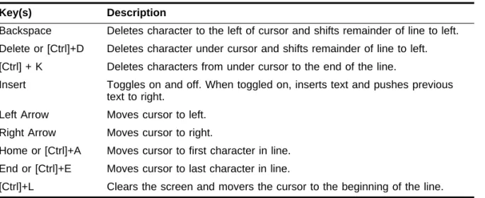
Table 4-2: Line-Editing Keys
Key(s) Description
Backspace Deletes character to the left of cursor and shifts remainder of line to left. Delete or [Ctrl]+D Deletes character under cursor and shifts remainder of line to left. [Ctrl] + K Deletes characters from under cursor to the end of the line.
Insert Toggles on and off. When toggled on, inserts text and pushes previous text to right.
Left Arrow Moves cursor to left. Right Arrow Moves cursor to right.
Home or [Ctrl]+A Moves cursor to first character in line. End or [Ctrl]+E Moves cursor to last character in line.
[Ctrl]+L Clears the screen and movers the cursor to the beginning of the line.
Table 4-1: Command Syntax Symbols (continued)
COMMAND HISTORY
C
OMMAND
H
ISTORY
The Summit ÒremembersÓ the last 50 commands you enter. You can display a list of these commands by using the following command:
history
C
OMMON
C
OMMANDS
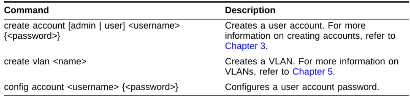
Table 4-3 describes common commands used to manage the Switch. Commands speciÞc to a particular feature are described in the other chapters of this guide. Up Arrow Displays the previous command in the command history buffer, and
places cursor at end of command.
Down Arrow Displays the next command in the command history buffer, and places cursor at end of command.
Table 4-3: Common Commands
Command Description
create account [admin | user] <username> {<password>}
Creates a user account. For more information on creating accounts, refer to
Chapter 3.
create vlan <name> Creates a VLAN. For more information on VLANs, refer to Chapter 5.
config account <username> {<password>} Configures a user account password.
Table 4-2: Line-Editing Keys (continued)
config devicemode [bridging | iprouting | ipmc ] Configures the operating mode of the Switch. Specify:
■ bridging — Layer 2 bridging functions only
■ iprouting — Bridging and IP unicast routing functions
■ ipmc — Bridging, IP unicast routing, and IP multicast routing functions If this command is used to change the operating mode of the Summit once it is up and running, it causes the Switch to save the configuration and reboot. The default operating mode is iprouting. config port <portlist> auto off {speed [10 | 100]}
duplex [half | full]
Manually configures the port speed and duplex setting of one or more ports. For more information on configuring ports, refer to Chapter 3.
config time <time> Configures the system date and time. The format for <time> is:
mm/dd/yyyy hh:mm:ss
The time uses a 24-hour clock format. config vlan <name> ipaddress <ip_address>
{<mask>}
Configures an IP address and subnet mask for a VLAN.
enable bootp vlan [<name> | all] Enables BOOTP for one or more VLANs. For more information on using BOOTP, refer to Chapter 3.
clear session <number> Terminates a Telnet session from the Switch.
disable bootp vlan [<name> | all] Disables BOOTP for one or more VLANs. disable port <portlist> Disables a port.
disable telnet Disables Telnet access to the Switch.
disable web Disables web access to the Switch.
delete account <username> Deletes a user account. delete vlan <name> Deletes a VLAN.
Table 4-3: Common Commands (continued)
SUMMIT COMMANDS
S
UMMIT
C
OMMANDS
The tables in this section list all of the commands used on the Summit Switch. The commands are organized by the following categories:
¥ General Switch commands
¥ User account commands
¥ Switch management commands
¥ VLAN commands
¥ Protocol commands
¥ FDB commands
¥ Port commands
¥ STP commands
¥ QoS commands
¥ Basic IP commands
¥ IP ARP commands
¥ IP Route Table commands
¥ ICMP commands
¥ RIP commands
¥ Logging commands
¥ ConÞguration and image commands
unconfig switch {all} Resets all switch parameters (with the exception of defined user accounts) to the factory defaults. If you specify the keyword
all, the user account information is reset as well.
Table 4-3: Common Commands (continued)
G
ENERALS
WITCHC
OMMANDSTable 4-4 describes general Switch commands.
Table 4-4: General Switch Commands
Command Description
show switch Displays the current Switch information, including:
■ sysName, sysLocation, sysContact ■ MAC address
■ Current date and time, and system uptime ■ Operating environment (temperature, fans,
and power supply status)
■ Nonvolatile Random Access Memory (NVRAM) image information
(primary/secondary image, date, time, size, version)
■ NVRAM configuration information (primary/secondary configuration, date, time, size, version)
■ Scheduled reboot information
■ System serial number and reworks indicator ■ Software platform
■ System ID
■ Power supply and fan status
show version Displays the hardware and software versions currently running on the Switch. Also displays the Switch serial number.
show memory Displays the current system memory
information.
reboot {<time>} Reboots the Switch at the time specified. If no time is specified, the Switch reboots
immediately following the command. config time <time> Configures the system date and time. The
format for <time> is:
mm/dd/yyyy hh:mm:ss
SUMMIT COMMANDS
U
SERA
CCOUNTC
OMMANDSTable 4-5 describes user account commands.
config devicemode [bridging | iprouting ] Configures the operating mode of the Switch. Specify:
■ bridging — Layer 2 bridging functions only ■ iprouting — Bridging and IP unicast
routing functions
If this command is used to change the operating mode of the Summit once it is up and running, it causes the Switch to save the configuration and reboot. The default
operating mode is iprouting. unconfig switch {all} Resets all Switch parameters (with the
exception of defined VLANs and IP addresses) to the factory defaults. If you specify the keyword all, the IP addresses are reset as well.
ping {continuous} {size <number>} <ipaddress> Sends ICMP echo messages to a remote IP device. Specify:
■ continuous — ICMP echo messages should be sent continuously.
■ size <n> — The size of the packet. The continuous option can be interrupted by pressing any key.
traceroute <ipaddress> Traces the routed path between the Switch and a destination endstation.
clear counters Clears all statistical counters for the Switch and ports.
Table 4-4: General Switch Commands (continued)
S
WITCHM
ANAGEMENTC
OMMANDSTable 4-6 describes Switch management commands.
Table 4-5: User Account Commands
Command Description
show account Displays the account names, access level, number of successful and failed login attempts, and the number of active sessions in the user database. This command is available only to admin level users.
create account [admin | user] <username> {<password>}
Creates a user account. delete account <username> Deletes a user account
config account <username> {<password>} Changes the password of an existing account.
Table 4-6: Switch Management Commands
Command Description
show management Displays network management configuration and statistics, including enable/disable states for Telnet and SNMP, SNMP community strings, authorized SNMP station list, SNMP trap receiver list, and login statistics.
show session Displays the currently active Telnet and console sessions communicating with the Switch. Provides the user name, IP address of the incoming Telnet session, whether a console session is currently active, and login time. Sessions are numbered.
clear session <number> Terminates a Telnet session from the Switch. logout | quit Logs out of a console or Telnet session. If
used during a Telnet session, also closes the TCP Telnet session.
enable telnet Enables Telnet access to the Switch. disable telnet Disables Telnet access to the Switch.
enable web Enables web access to the Switch. Requires a reboot to take effect.
SUMMIT COMMANDS
disable web Disables web access to the Switch. Requires a reboot to take effect.
enable snmp access Turns on SNMP support for the Switch. disable snmp access Disables SNMP on the Switch.
enable snmp trap Turns on SNMP trap support.
disable snmp trap Prevents SNMP traps from being sent from the Switch. Does not clear the SNMP trap receivers that have been configured.
config snmp add <ipaddress> Adds the IP address of an SNMP management station to the access list. Up to six addresses can be specified.
config snmp delete [<ipaddress | all] Deletes the IP address of a specified SNMP management station or all SNMP
management stations. config snmp add trapreceiver <ipaddress>
{<comm_string>}
Adds the IP address of a specified trap receiver. A maximum of six trap receivers is allowed.
config snmp delete trapreceiver [<ip_address> community <string> | all]
Deletes the IP address of a specified trap receiver or all authorized trap receivers. If you delete all trap receiver addresses, any machine can have SNMP management access to the Switch.
config snmp community [read | readwrite] <string>
Configures the SNMP read and write
community strings. The community string can have a maximum of 127 characters.
config snmp syscontact <string> Configures the name of the system contact. A maximum of 255 characters is allowed config snmp sysname <string> Configures the name of the Switch. The
sysname appears in the command-line interface prompt. A maximum of 255
characters is allowed. The default sysname is Summit1 or Summit2.
config snmp syslocation <string> Configures the location of the Switch. A maximum of 255 characters is allowed.
Table 4-6: Switch Management Commands (continued)
VLAN C
OMMANDSTable 4-7 describes VLAN commands.
Table 4-7: VLAN Commands
Command Description
show vlan {<name> | all> When used with the keyword all, or with no named VLANs, displays a summary list of VLAN names with a portlist and associated status of each. When used with a named identifier, displays port information, including membership list, IP address, and tag information.
create vlan <name> Creates a named VLAN. delete vlan <name> Removes a VLAN. config vlan <name> [add | delete] port
<portlist> {tagged | untagged}
Adds and deletes ports. You can specify tagged and untagged port(s). By default, ports are untagged.
config vlan <name> tag <vlanid> Assigns a numerical VLANid. The valid range is from 1 to 4095.
config vlan <name> protocol [<protocol_name> | any]
Configures a protocol-based VLAN. If the keyword any is specified, then it becomes the default VLAN. All packets that cannot be classified into other protocol-based VLANs are assigned to the default VLAN of that port. config vlan <name> qosprofile <qosname> Configures a VLAN to use a particular QoS
profile. Dynamic FDB entries associated with the VLAN are flushed once this change is committed.
config vlan <name> ipaddress <ipaddress> {<mask>}
Assigns an IP address and an optional mask to the VLAN.
config dot1q ethertype <ethertype> Configures an IEEE 802.1Q Ethertype. Use this command if you have another Switch that supports 802.1Q, but uses a different
Ethertype. The default value used by the Switch is 8100.
unconfig vlan <name> ipaddress Removes the IP address associated with a VLAN.