TX20ETH
Measuring wind speed and direction
Intelligent anemometer with Ethernet
T X 2 0 E T H
Datasheet
Created: 9/11/2009 Last update: 12/12/2013 12:32 Number of pages: 40 © 2013 Papouch s.r.o.P a p o u c h s . r . o .
Address:Strasnicka 3164
102 00 Prague 10
Czech Republic
Tel:+420 267 314 268
Fax:+420 267 314 269
Internet:www.papouch.com
E-mail:[email protected]
TABLE OF CONTENTS
Basic Information ... 4
Description ... 4
Main features ... 5
How to get values from TX20ETH ... 6
Detailed Features ... 7 List of versions ... 8 Design ... 8 Contents of Package ... 9 Connection... 10 Device Configuration ... 11 Ethernet Configurator ... 11
Configuration via web interface ... 11
Network ... 13 Device Reset ... 14 Security ... 15 E-mail ... 16 SMTP authorisation ... 16 Settings test ... 16 SNMP ... 17 Sending ... 18 HTTP GET ... 18 Values ... 19 Value Watchdog ... 19 Other ... 20 MODBUS TCP ... 20 Info ... 21 Telnet configuration ... 22 Connection ... 22 Unknown IP address ... 22 IP address is known ... 23
Telnet main menu ... 23
Server ... 23
Factory Defaults ... 24
Exit without save ... 24
Save and exit ... 24
options for connecting to TX20ETH ... 25
WEB interface ... 25
Simplify ... 26
Displaying values from several devices on one page ... 26
Displaying the values on the mobile phone or PDA ... 27
XML file ... 28
status ... 28
sns ... 28
Values transmission to the server using HTTP GET ... 29
HTTP GET ... 29
Connection via TCP – TCP and UDP modes . 31 SNMP ... 32
Introduction ... 32
Use of SNMP ... 33
SNMP objects – variables ... 33
SNMP objects – general ... 34
Automatic messages – traps ... 34
Sending of emails ... 36
Exceeding of some of the pre-defined limits36 MODBUS protocol ... 37
Memory table – Input Register ... 37
Values and latest statuses of individual channels ... 37
FAQ ... 38
Which settings are required for TX20ETH to work in my network? ... 38
How to find out the IP address of the device? ... 38
Indication ... 39
device reset ... 39
BASIC INFORMATION
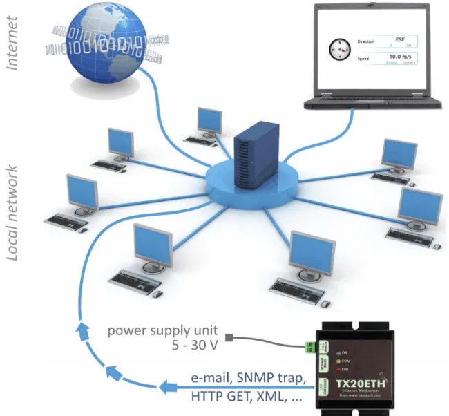
D e s c r i p t i o nTX20ETH is an Ethernet anemometer, which is able to measure wind speed and direction. It is connected directly to a computer network (Ethernet). Measured data can be processed automatically or by operating personnel. Wind speed and direction is displayed on the internal web interface. When limits are exceeded TX20ETH is able to notify the operator via e-mail. For automatic operation and processing, TX20ETH is able to communicate by a data channel via TCP, using protocols SNMP and MODBUS TCP. It can also send messages to a remote server via simple HTTP GET requests. Values from TX20ETH as well as setup are easily accessible even in the XML format.
Sensor configuration is carried out via web interface. Help is available for all parameters in Czech and English language versions.
M a i n f e a t u r e s
Wind speed measuring up to 50 m/s (i.e. up to 180 km/h) resolution 0.1 m/s.
Wind direction measuring – 16 positions within the whole range of 360°.
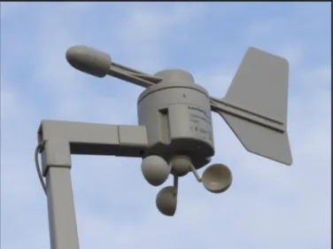
It is possible to use a standard mechanical sensor.
Fig. 2 – wind speed and direction sensor
Connection and communication via computer network (Ethernet).
Data transmission via TCP/IP protocols (10/100 Ethernet).
Configuration via web interface.
Power supply 7 V to 30 V (a supplied socket adapter).
Measuring monitoring options:
1. Internal web page with undated values.
2. Possibility to display values from several TX20ETHs on one web page. 3. Automatic sending of values via HTTP GET request.
4. Current values and all configurations easily accessible in the XML format. 5. Automatically sends e-mails when set limits are exceeded.
6. Communication via TCP channel using the Spinel protocol. 7. SNMP protocol.
8. MODBUS TCP protocol. 9. Via the Wix program for PC.1
1
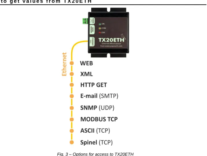
H o w t o g e t v a l u e s f r o m T X 2 0 E T H
Fig. 3 – Options for access to TX20ETH
1) WEB site
After entering the IP address of the device into the internet browser2, the relevant internet page is displayed showing the latest measured values. The website of TX20ETH is available in Czech and English depending on the configuration. The system can be configured to display values from several TX20ETHs simultaneously on one page. (For more information see page 25.)
2) XML file
A file in the XML format containing the latest measured values, name of the point of measurement, etc. is available at the address http://[IP_adresa]/fresh.xml. (For more information see page 26.)
3) Easy transfer of measured values to your server using HTTP GET
TX20ETH enables you to periodically call a script (e.g. PHP) using your web server. The script receives from TX20ETH measured values in a parameter of the HTTP GET type.
(For more information see page 29.)
2
Web interface requires JavaScript to be enabled. The interface is optimised for the following browsers: Internet Explorer 7.0, Mozilla Firefox 3.0, Opera 9.6 and Google Chrome 1.0. The minimum recommended resolution for comfortable use is 1024 × 768 pixels.
4) SNMP protocol
According to its configuration, TX20ETH sends SNMP traps whenever the measured values exceed the set limits. It also enables regular sending traps with the latest measured values. This data can also be recalled from integrated SNMP objects whenever needed. (For more information see page 31).
5) MODBUS TCP Protocol
TX20ETH is also able to communicate via a standard industrial protocol – MODBUS TCP. (See page 36.)
6) Via email
According to its configuration TX20ETH sends notifications via email whenever the measured values exceed the set limits. (See page 32.)
7) Spinel (TCP protocol)
In a special mode, TX20ETH is able to communicate via the Spinel protocol. It is possible to choose whether it shall act as a TCP server or a TCP client. The device uses Spinel to communicate the standard way: request-response. Complete documentation of the protocol, including some examples, is available in a separate document.
D e t a i l e d F e a t u r e s Network
Configuration of the IP address, netmask, gateway, web port number and DNS server address.
Selection of communication mode: WEB, TCP server, TCP client or UDP. In the modes of TCP and UDP it is possible to communicate with TX20ETH via data connection using the Spinel protocol.
Configuration of the local and remote data port.
Restoring the default setting by pressing the Reset button via web.
Security
Two-level security – user (can only view the measured values) and administrator (can also configure the device)
A different password for each level.
E-mails
Sending an email when the limits are exceeded (Can be forwarded to your mobile.3)
SMTP authorization of the sender.
Possibility to sent a test email to verify the configuration.
SNMP
Sending a SNMP trap when the limits are exceeded.
3
Recalling the latest values from internal SNMP objects.
Community configuration for reading and making records.
HTTP GET
Periodic sending of the latest measured value(s) to your web server using a simple HTTP GET request.
For TX20ETH identification, the GET request contains also the MAC address.
Measuring
Measuring of wind speed and direction from an external sensor.
Possibility to the lower and upper limit for each variable. If any measured value exceeds the set range, the device will send an e-mail and/or a SNMP trap, according to the configuration. Sending can be delayed until the limit is exceeded for a given period.
Activate monitoring values separately for each channel.
Hardware
Wind direction measuring – sixteen possible directions.
Wind speed measuring – up to 50 m/s with 0.1 m/s resolution.
Length of cable connecting the sensor: 10 metres.
Power supply: 5 to 30 V (adapter is included in the delivery).
Other
Possibility to name the device as required.
Configuration of a port for MODBUS TCP.
Web interface available in two language versions – Czech or English.4
Possibility to simplify the web display. (E.g. for easy displaying of variables from several sensors on a single web page using HTML IFrame.)
The web interface requires JavaScript to be enabled. The interface has been optimised for the following browsers: Internet Explorer 9.0, Mozilla Firefox, Opera and Google Chrome. The recommended minimum resolution for comfortable use is 1024 × 768 pixels.
L i s t o f v e r s i o n s Version 1.0
The first version.
Version 2.0
Multiple wind speed units available (m/s, mph, km/h, kt).
WAP page no longer available (main WEB optimized for mobile devices).
4
D e s i g n Electronics
In a metal box made of anodized aluminium.
Sensor
Plastic sensor with mechanical detection of wind direction and speed.
Assembly
Without a mounting clip (standard design) With a mounting clip for 35 mm DIN rail
Fig. 4 – Design with mounting clip for 35 mm DIN rail
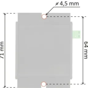
With a wall mounting plate
Fig. 5 – Wall mounting plate dimensions
Power Supply
7 to 30 V DC (The 12 V power supply unit (adapter) is included in the delivery.)
Do not hesitate to contact us if you have any other special requirements concerning the design and functions of the TX20ETHsensor.
C o n t e n t s o f P a c k a g e
Sensor electronics and a sensor for wind direction and speed measuring.
12 V power supply unit (socket adapter).
CONNECTION
1) Install the wind speed and direction sensor. (Please note that the sensor must be installed in the proper position in accordance with the cardinal directions marked on the sensor.)
2) Connect TX20ETH to power supply using the supplied adapter or another power supply unit of 7 to 30 V.
3) Then connect TX20ETH to the Ethernet (PC network) using the supplied cable5. (If you want to connect TX20ETH directly to a single PC, use a crossover cable.)
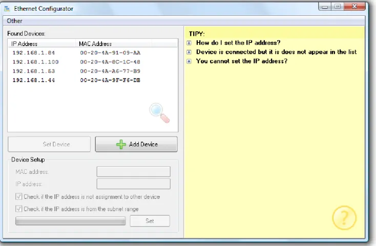
4) If the IP address range of your network is not compatible with the default IP address (192.168.1.254) and netmask (255.255.255.0) of TX20ETH, set an address which is suitable for your network using the Ethernet Configurator program. This software is available on www.papouch.com.
Fig. 6 – Ethernet Configurator for IP address setting
5) After having set the IP address you can connect to TX20ETH using your web browser. The relevant web interface is available directly at the IP address of TX20ETH. Open your web browser and enter the address of the device: http://192.168.1.254/ (this example uses the default IP address, which has been set by the manufacturer).
5
DEVICE CONFIGURATION
Configuration of TX20ETH can be performed using:
Web interface
Telnet protocol (see page 21)
Ethernet Configurator for the initial configuration of the IP address
E t h e r n e t C o n f i g u r a t o r
Ethernet Configurator is used for setting the IP address of the device. The relevant software is available on www.papouch.com.
(Before running the software, connect the device to your computer network. Connect it either to a hub, switch, router or directly to a PC using a crossover cable.)
The program is available in Czech and English language and contains brief instructions helping the user to set the required IP address.
A sample screen from the program is shown in Fig. 6 on the previous page.
CONFIGURATION VIA WEB INTERFACE
To enter the configuration mode, press the button in the upper right-hand corner of the main webpage of TX20ETH.
Fig. 7 – Button opening the configuration mode from the main page
Configuration options have been arranged into the following eight tabs:
Network – to configure the interface, IP address, netmask, DNS server, mode, … Security – to set the passwords for web access
E-mail – receiver, authorization, configuration test
SNMP
Sending – to send values to your server using HTTP GET Values – to set the limits
Others – device name, MODBUS TCP and language Info – information about the device
Tips for working with the settings:
The default language of the website is English. The web can be switched into Czech by changing the Language parameter in the Other tab.
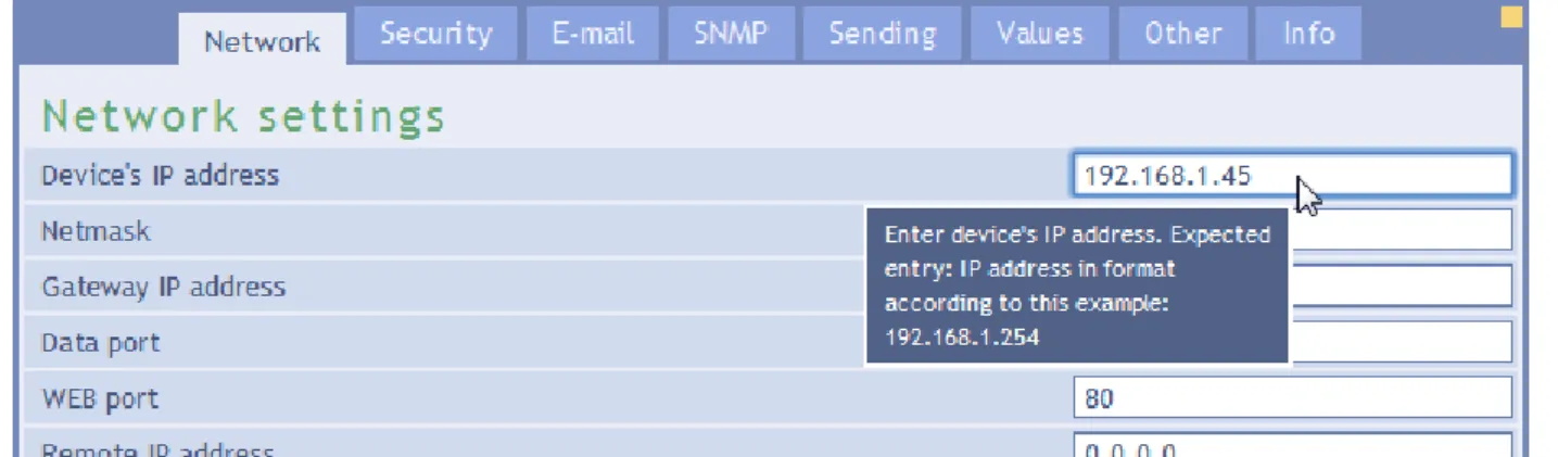
Help for all configuration items is displayed when you scroll the pointer over the relevant field. (You can also display Help by scrolling the pointer over headings marked with a question mark.)
Fig. 8 – Instant help displayed using the mouse cursor
The configuration window can be moved by clicking and holding the upper right-hand corner of the screen.
The configuration window can also be accessed by pressing the S key when the web browser window is active.
The configuration window can be closed by pressing the Esc key when the web browser window is active.
N e t w o r k
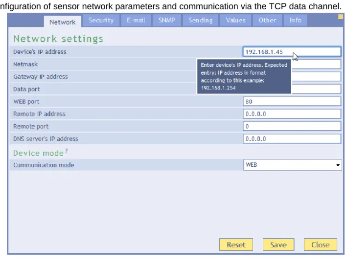
Configuration of sensor network parameters and communication via the TCP data channel.
Fig. 9 – Network configuration tab
Device’s IP address
The IP address of TX20ETH. In case you are not sure which IP address to enter, ask your network administrator.
Netmask
The mask of the network the TX20ETH is connected to.
Gateway IP address
Address of the network gateway.
Data port
TCP server mode: number of data port. Port functions depend on the set mode (see below). This is the port where TX20ETH expects incoming connections. After a connection has been established, the device expects request in the Spinel protocol
Web port
This is the number of port where the web interface is available, number 80 or 8080.
Remote IP address
IP address of a remote device (usually a server) to which TX20ETH connects in the TCP client mode. The established connection communicates via the Spinel protocol.
Remote port
Port number of a remote device (usually a server) to which TX20ETH connects in the TCP client mode. The established connection communicates via the Spinel protocol.
DNS server’s IP address
IP address of the DNS server in your network.
Device mode
WEB: The mode in which it is possible to use all the available functions of the device, except for data communication via the Spinel protocol.
In the following modes it is not possible to view the latest values on the website, to send emails and HTTP GET messages, to use SNMP and MODBUS TCP. In these modes the device communicated via the Spinel protocol.
TCP server: TX20ETH passively waits for connection to be established on the preset port (Data port).
TCP client: TX20ETH actively establishes connection with a remote IP address (Remote IP address) and port (Remote port).
UDP: TX20ETH communicated using the UDP protocol. Incoming messages are expected on the Data port.
D e v i c e R e s e t
By pressing this button it is possible to restore the default setting of all the parameters of the device. Only the IP address does not change. The web port is changed to 80.
S e c u r i t y
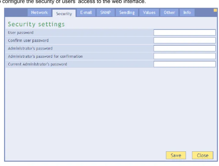
To configure the security of users’ access to the web interface.
Fig. 10 – Security configuration tab
User password and Confirm user password 6
Here, enter the password for user’s access. This security level only enables the user(s) to monitor the measured values. Access to the configuration options is disabled.
User’s log-on name is always “user”
If a user password has been set, it is also necessary to set an administrator password.
If only an administrator password has been set, the log-on window opening up when accessing the TX20ETH page can be confirmed without entering any details.
If you want to cancel the password, leave the fields empty.
Administrator’s password and Administrator’s password confirmation 6
Here, enter the password for administrator’s access. This security level enables, besides monitoring the values, also configuration of the device.
Administrator’s log-on name is always “admin”
If you want to cancel the password, leave the fields empty.
6
The field only serves for entering the required values. After saving the values, no configuration is displayed for security reasons.
Current administrator’s password 6
If the administrator has a password set for the current login, enter it here. It is not possible to change nay passwords without entering the current one.
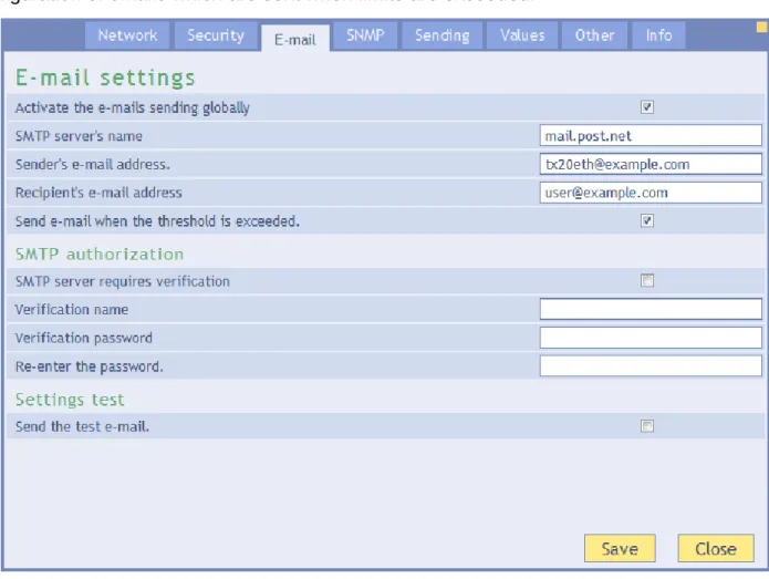
E - m a i l
Configuration of emails which are sent when limits are exceeded.
Fig. 11 – Email configuration tab
SMTP server’s name
Enter the name or IP address of the SMTP server which is to be used to send the emails.
Sender’s email address
A fictitious address of TX20ETH – an address from which the messages will be sent.
Recipient’s email address
An email address to which the messages are to be sent.
S M T P a u t h o r i s a t i o n
Here it is possible to enter log on details if the used SMTP server requires sender’s identification to be verified. 7
S e t t i n g s t e s t
Sending a testing email to verify whether the configuration has been carried out correctly.
7
The field only serves for entering the required values. After saving the values, no configuration is displayed for security reasons.
S N M P
To set parameters for communication via the SNMP protocol. Activation of traps, periodic sending of values, etc.
Fix. 12 – SNMP configuration tab
SNMP manager’s IP address
IP address of the server collecting the SNMP messages from devices within the network.
Allow trap sending
Enables SNMP traps to be sent to the manager, which is specified below.
Send SNMP trap when threshold is exceeded
If any measured values exceed the limits set in the Values tab, a trap is send with information about this event.
Periodical sending of measured-out values
Here it is possible to enter the frequency in which the values are to be sent into the SNMP manager. The values are sent in the form of SNMP traps. The frequency is set in minutes. If you do not with to use this function, set the frequency to 0.
Read community name
The name of the SNMP community for reading.
Write community name
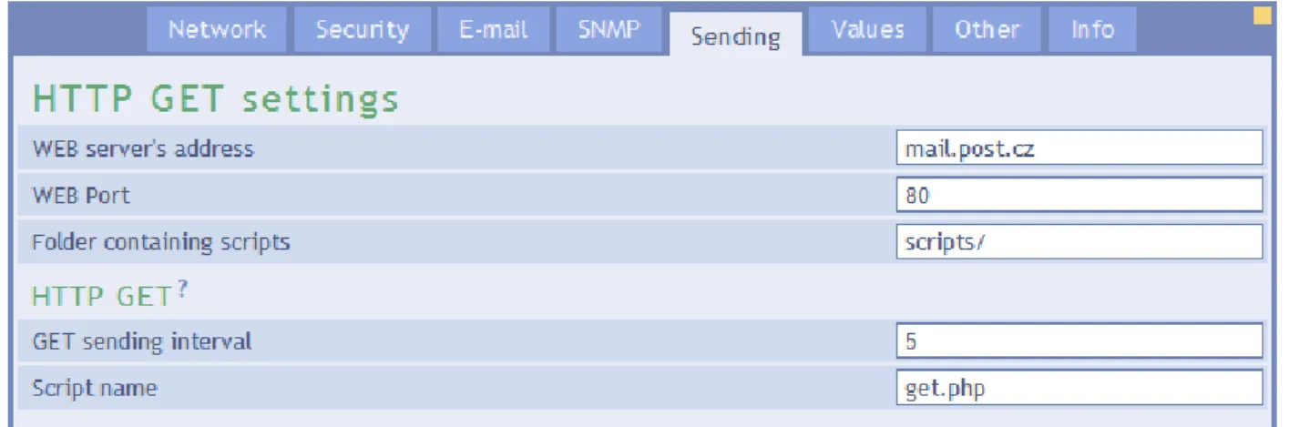
S e n d i n g
Parameters for automatic sending of values to the server via the HTTP protocol. HTTP GET is used for sending the values.
Fig. 13 – Configuration tab for sending values via HTTP protocol
Web server’s address
Here you enter the URL address or IP address of the web server which is to receive the measured values. If you are not sure which address to enter, contact your server administrator.
Web port
Web port number of the server which is to receive the measured values. Usually, this is number 80, sometimes 8080.
Folder containing scripts
Here, enter the local path to the script directory. If the script receiving the results is
www.server.net/scripts/get.php, enter the following part: scripts/
H T T P G E T
GET can be used for periodic sending of measured values.
GET sending interval
Enter the frequency in which the measured values are to be sent. The frequency is set in minutes.
Script name
V a l u e s
Configuration of limits for the measured variables. After entering this tab it is necessary to choose the required variable by clicking its name in the upper part of the configuration window.
Fig. 14 – Values configuration tab
Wind speed units
Wind speed can be viewed in multiple units: m/s, mph, km/h or kt.
V a l u e W a t c h d o g Activate values watching
If this field is ticked, the system watched the limit values set below.
Maximal value
When this value is exceeded, an e-mail, SNMP trap, etc. is sent depending on the configuration. The value is highlighted on the web site to indicate that it is outside the permissible range.
Minimal value
When a value is measured which is below this limit, an e-mail, SNMP trap, etc. is sent depending on the configuration. The value is highlighted on the web site to indicate that it is outside the permissible range.
Alarm delay
O t h e r
Here, you can set the name of the device, language and MODBUS port.
Fig. 15 – Tab for setting other parameters
Name of the device
This field can be used to give each device a name, for example according to its location etc. (Only characters without diacritical marks can be entered.)
Language
Here, you can set the language of the web site. You can choose from Czech and English language versions.8
M O D B U S T C P ModBus Port
Here, it is possible to set the number of port for communication via the MODBUS TCP protocol.
8
I n f o
This tab cannot be configured but contains various types of information about the device, its MAC address, for example.
Fig. 16 – Tab with information about the device
Links
TELNET CONFIGURATION
C o n n e c t i o n
U n k n o w n I P a d d r e s s
For setting the IP address we recommend using Ethernet Configurator (more on page 11).
1) Open a window with command prompt (In Windows OS, click Run and type cmd.) 2) Make a record to ARP table:
a. Type arp –d and confirm by Enter. That deletes current ARP table. b. Following command assigns IP address to MAC address:
arp –s [new_ip_address] [MAC_address]
example: arp -s 192.168.1.254 00-20-4a-80-65-6e
3) Open Telnet. ( by typing telnet and pressing Enter9) 4) Type open [new_ip_address] 1 and confirm.
5) Terminal shows an error message after a moment. Nevertheless this action is essential for correct IP address ARP entry.
6) Connect to the IP address of the device. (by typing open [IP address in dot format] 9999 and Enter.)
7) Now you have entered to the configuration of device. IP address is not yet set. It needs to be set in menu Server Configuration > IP Address.
8) If the IP address is valid, device writes welcoming information ending by text:
Press Enter for Setup Mode
Now press Enter or the configuration will be terminated. 9) Device writes complete settings.
10) At the end of the entry you can see „Change setup:” text containing groups of parameters that are configurable. For changing the network parameters choose Server. Here you can set a new IP address and other parameters.
9
Telnet client is not standardly installed in OS Windows Vista. You can install it by doing following: a) Open Control panel/add or remove programs.
b) On the left, click on Add/remove Windows functions (You have to have administrator’s rights to do this.) c) Windows Functions window will open. Check “Telnet client” and confirm. Telnet client will be installed to
I P a d d r e s s i s k n o w n
1) In OS Windows click on Start/Run and type telnet and confirm. 9
2) Connect to the IP address of the device. (by typing open [IP address in dot format] 9999 and Enter.)
3) If the IP address is valid, device writes welcoming information ending by text:
Press Enter for Setup Mode
Now press Enter or the configuration will be terminated. 4) Device writes complete settings.
5) At the end of the entry you can see „Change setup:" text containing groups of parameters that are configurable. For changing the network parameters choose Server.
T e l n e t m a i n m e n u
You can choose the menu items by pressing the number before them and confirming by Enter. Menu structure is:
Change Setup: 0 Server
...
7 Defaults
8 Exit without save
9 Save and exit Your choice ?
S e r v e r
Basic Ethernet settings.
Following items are in this part:
IP Address : (192) .(168) .(001) .(122) Set Gateway IP Address (N) ?
Netmask: Number of Bits for Host Part (0=default) (16) Change telnet config password (N) ?
IP Address
Device’s IP address. Enter the numbers separately and divide them by Enter. Default: 192.168.1.254
Set Gateway IP Address Gateway IP address
Type “Y” in the “Set Gateway IP Address” item to change the address. Enter the numbers separately and divide them by Enter.
Netmask
You can set here how many bits from IP address make the network part.
Subnet mask is entered as a number of bits determining range of possible IP addresses of the local network. If for example 2 is entered, subnet mask is 255.255.255.252 . Entered value indicates number of bits from right. Maximum is 32.
Default: 8 Example:
Mask 255.255.255.0 (binary 11111111 11111111 11111111 00000000) -> number 8. Mask 255.255.255.252 (binary 11111111 11111111 11111111 11111100) -> number 2.
Change telnet config password Enter new Password
This item sets the password that is required before entering the Telnet configuration or via WEB interface (Administrator’s password).
Type “Y” at „Change telnet config password“ to change the password
F a c t o r y D e f a u l t s
By pressing number 7 you can set the device to factory defaults.
This option sets the device to defaults. IP address does not change, WEB port number will be changed to 80.
E x i t w i t h o u t s a v e
Ends the telnet session without saving.
S a v e a n d e x i t
This choice saves the changes. If some settings are changed, device restarts. That may take up to 30 seconds.
OPTIONS FOR CONNECTING TO TX20ETH
For a brief overview of methods which can be used to read the values from TX20ETH see page 5.
W E B i n t e r f a c e
After entering the IP address of the device into the web browser10 the page shown in Fig. 17 is displayed.11 This page contains the latest measured values, sensor name (if entered) and the set limits. In case any limit is exceeded, it is highlighted. The latest measured values can only be viewed in the WEB mode (see Device mode on page 14).
Here, it is possible to press the Configuration button in the upper right-hand part of the window to display the configuration window. (The button in only enabled for the administrator.)
Fig. 17 – Basic window of the Web mode
The website is available in Czech and English languages.
10
Web interface requires JavaScript to be enabled. The interface is optimised for the following browsers: Internet Explorer 9.0, Mozilla Firefox, Opera and Google Chrome. The minimum recommended resolution for comfortable use is 1024 × 768 pixels. The address should be entered into the following format:
http://[IP_adresa_TX20ETH]/ , e.g. http://192.168.1.254/ for TX20ETH in the default configuration.
11
If you wish a different design of the web interface or you want it to include the logo of your company etc, do not hesitate to contact us.
S i m p l i f y
By clicking the Simplify button, the current window is displayed in a simpler form. This form is suitable e.g. when it is necessary to make the display smaller or when it is required to display values from several devices on one page (more information about this option is available below the following figure).
Fig. 18 – Simplified display
D i s p l a y i n g v a l u e s f r o m s e v e r a l d e v i c e s o n o n e p a g e
If your system employs more devices, the values received from them can be displayed together on a single web page. An example of this option is shown in the following figure containing values from several anemometers.
Fig. 19 – Displaying values from several devices on one page
If you wish to display mode devices on a single web page, follow the instruction below: 1) Create a new file called test.html, for example
2) Copy the following text into the file:
<!DOCTYPE HTML PUBLIC "-//W3C//DTD HTML 4.01//EN" "http://www.w3.org/TR/html4/strict.dtd">
<html> <head>
</head> <style>
body {background-color: WHITE;}
iframe {border: none; width: 450px; height: 240px;} </style> <body> <iframe src="http://192.168.1.254/index.html?mini"></iframe> <iframe src="http://192.168.1.121/index.html?mini"></iframe> </body> </html>
3) The number of devices to be displayed depends on the number of lines starting with
<iframe. These lines can be added according to your needs. Just replace the IP addresses shown in the lines (highlighted in red) with the IP addressed of your devices. 4) Save the file to your hard drive, to a server within your company’s intranet or to the
internet if you want to enable other users to use it as well. (If you save the file to a server, the addresses in the lines starting with iframe must be entered from the point o view of the particular server, the server must be able to access these IP addresses.)
5) If you save the file directly to e.g. disk C, you display the page in your web browser by entering the following address: file:///C:/test.html
D i s p l a y i n g t h e v a l u e s o n t h e m o b i l e p h o n e o r P D A
By clicking the Mobile version button, you display a simple page which is suitable for displaying the values on the mobile phone. The mobile version of the website is available at
X M L f i l e
It is possible to obtain the latest measured values, pre-set limits and device name from TX20ETH in the text file of the XML format. The file is available at the address
http://[IP-address]/fresh.xml – e.g. at http://192.168.1.254/fresh.xml for TX20ETH in the default setup.
Fig. 20 – XML sample with the latest values
The XML file contains sns tags for each variable and as well the status tag:
s t a t u s location
User-defined name of the device.
s n s id
Variable sequence number. (starting with 1)
type
Variable type. It can take the following values: 6 ... wind direction
7 ... wind speed
status
Describes the status of the measured value. It can take the following values: 0 ... the value is valid and it represents the latest measured value 1 ... waiting for the first measurement
2 or 3... the measured value exceeded the user-defined limits
4 ... measurement error or sensor error (meaning damaged or disconnected sensor)
val
Wind direction: Wind direction index in the range of 0 to 15. 0 stands for the North. 1 is the North-North-East, 2 is the North-East, etc. clockwise. (The status attribute indicates the validity of the value.)
Wind speed: the latest measured value of the wind speed expressed as an integer. It represents the actual value multiplied by 10. The wind speed of 15.2 m/s is displayed as number 152 in the xml. (The status attribute indicates the validity of the value.)
vals
This attribute is present only for wind direction and contains an English abbreviation for wind direction. (The status attribute indicates the validity of the value.)
This attribute is present for wind speed only and consists of numeric representation of the currently set units. It can be one of the following options:
0 ... m/s 1 ... mph 2 ... km/h 3 ... kt
w-enb
This attribute indicates whether the watchdog monitoring the measured values is active. The value 1 means that the watchdog is activated, 0 shows that it is disabled.
w-min, w-max
The lower (w-min) and upper (w-max) limit of the value defined by the user. The value is shown as an integer like the val value. (Limits are watched only when the w-enb attribute is set to 1.)
V a l u e s t r a n s m i s s i o n t o t h e s e r v e r u s i n g H T T P G E T
It is possible to transmit the measured values to your server using a scripting language (for example PHP) which processes the value sent by the device as the HTTP parameter of the GET request. The device periodically calls the script on the server in the Internet (or the company Intranet) with the latest measured values in the GET parameter. It is possible to store this value into the variable on the server and to work with it further – for example to store it into a database or to display it on the web.
The path to the script and the script calling frequency is specified in the setup. It is possible to set the transmission frequency in the range of 1 to 1440 minutes with 1-minute increments.
H T T P G E T
In this request type, parameters are sent in the message address as standard HTTP GET parameters. An example:
http://www.example.com/script.php?mac=00204AB48DF1&name=Downhill&
directionS=0&directionV=270.0&speedS=0&speedV=17.4
As is evident from the example above, the request has the format well-known to web programmers. It is not necessary to learn new programming principles as it is sufficient to use the mechanism known from web form processing (<form name="myform" method="get" action=…).
The request is sent in the interval specified in the item GET sending interval on page 18. GET parameters are as follows:
mac ... a unique MAC address of the device.
name ... User-defined device name.
directionS ... describes the wind direction status. It can take the values:
0 ... the value is valid and it represents the latest measured value 1 ... waiting for the first measurement
4 ... the value is not valid – measurement error or sensor error (damaged sensor or cable)
directionV ... Wind direction expressed as an integer in the range of 0 to 359. (The value in degrees from the North clockwise.)
speedS ... Describes the wind speed status. (It takes the same values as the direction.)
speedV ... Measured wind speed in the set-up units.
How to set HTTP GET – examples
(The context help for entering the script path is displayed on the web interface when the mouse cursor is scrolled over the title HTTP GET.)
The Example 1:
Instructions:
The script script.asp is prepared on the server awaiting the data from TX20ETH. The full address of the script on the server is http://www.example1.net/script.asp
Solution:
It is necessary to set the following items:
Web server address ... www.example1.net Web port ... 80
Script directory on the server ...
Script name ... script.asp The called URL:
http://www.example1.net/script.asp?mac=00204AB48DF1&name=Outside&directionS=0& directionV=45.0&speedS=0&speedV=16.2
The Example 2 – measurement error:
Instructions:
The script get.php is prepared on the server awaiting the data from TX20ETH. The full address of the script on the server is http://www.example.com/ext/get.php
Solution:
It is necessary to set the following items:
Web server address ... www.example.com Web port ... 80
Script directory on the server ... ext/ Script name ... get.php The called URL:
http://www.example.com/ext/get.php?mac=00204AB48DF1&name=Outside&directionS=0& directionV=45.0&speedS=0&speedV=16.2
C o n n e c t i o n v i a T C P
– T C P a n d U D P m o d e s
In the TCP server, TCP client and UDP modes, TX20ETH communicates via the Spinel protocol. It is a standard request-response protocol used by all devices in our company. It can be used to configure TX20ETH as well as to read parameters and measured values.
A detailed documentation of the Spinel protocol in TX20ETH, including commented examples, is contained in a separate document on www.papouch.com in the section dedicated to TX20ETH.
S N M P
I n t r o d u c t i o n
The SNMP protocol (Simple Network Management Protocol) is a standard protocol dedicated for the maintenance of various end devices connected to the Ethernet network. It works over the UDP protocol and it provides quick delivery of controlling requests and responses between devices running SNMP applications.
SNMP is responsible for delivering these requests and responses on behalf of the mentioned applications. It works independently from specific functions of the applications, lower layers architecture or upper layers applications. The protocol contains three basic entities – the administrator (generating commands and receiving notifications), the agent (responding to the commands and creating notifications) and the proxy (handing over the network traffic).
The SNMP administrator sends requests to UDP port 161 of the agent and receives messages (traps) from agents on UDP port 162.
placing enquiries for the data stored in the local MIB database (Management Information Base
– one of the Internet standards) formed by the hierarchical tree of the maintained values. The device does not contain a standard complex database but only the sub tree necessary for the processing of the data from TX20ETH.
The description of the directory tree of the MIB table and SMI (Structure of management information) are attached to the device as the text file TX20ETH_v01.MIB 12. It is necessary for the programmer to include these two descriptions into the structure of the SNMP administrator (SNMP version 2.0).
It is possible to access the data in MIB by entering the object name, expressed as a series of positive integers, divided by points, describing the path to the object within the MIB tree.
TX20ETH, as the SNMP agent, enables sending of automatic messages (traps) to the administrator to UDP port 162.
U s e o f S N M P
Into your SMNP manager implement the description of the agent’s MIB table from TX20ETH_v01.MIB.
Then, it is necessary to set the Read community to public (for the default setting of TX20ETH). All SNMP objects in TX20ETH are only available for reading.
S N M P o b j e c t s – v a r i a b l e s
The following objects are available for both the direction and the speed of the wind. The wind direction has 1 as the last digit in the id object, the speed is marked as 2.
Variable status
Name: inChStatus
Object ID: 1.3.6.1.4.1.18248.20.1.2.1.1.1.1 to 2
Description: The status of this variable. It describes the latest status of the measurement. It can take one of the following clauses:
0 The value is valid and within the range. 1 The value has not been measured yet.
2 or 3 The value is valid and exceeds the pre-set limits. 4 The value is not valid –measurement error.
Measured value
Name: inChValue
Object ID: 1.3.6.1.4.1.18248.20.1.2.1.1.2.1 to 2
Description: The measured value expressed as an integer. The real value can be obtained by dividing it by 10. Value watchdog Name: modeWatch 12 Available on www.papouch.com.
Object ID: 1.3.6.1.4.1.18248.20.1.3.1.1.1.1 to 2
Description: It indicates the status of watching the value from this channel. 1 means that the watching is active. 0 means that the watching of the value from this channel is inactive.
Upper limit
Name: limitHi
Object ID: 1.3.6.1.4.1.18248.20.1.3.1.1.2.1 to 2
Description: Upper limit of the measured value watching. When this limit is exceeded, a trap or an e-mail is sent, the value is highlighted on the web etc. according to configuration.
Lower limit
Name: limitLo
Object ID: 1.3.6.1.4.1.18248.20.1.3.1.1.3.1 to 2
Description: Lower limit of the measured value watching. When this limit is exceeded, a trap or an e-mail is sent, the value is highlighted on the web etc. according to configuration.
S N M P o b j e c t s – g e n e r a l
The following two objects refer to the whole device.
Device name
Name: deviceName
Object ID: 1.3.6.1.4.1.18248.20.1.1.1.0
Description: User-defined device name.
Alarm tect
Name: psAlarmString
Object ID: 1.3.6.1.4.1.18248.20.1.1.2.0
Description: The text of the alarm message when the pre-set limits are exceeded.
A u t o m a t i c m e s s a g e s – t r a p s
TX20ETH enables to send automatic messages (SNMP traps). Two settings correspond to the traps: sending permission and the IP address of the traps recipient (a so called administrator or SNMP manager).
Traps are sent (depending on configuration) if any value exceeds the pre-defined limits. It is possible to send traps with the latest values periodically according to the configuration.
Trap 1 – Value outside the limits
The trap contains the measured value and the exceeded limit.
Trap is sent only in the case a pre-defined limit has been exceeded. To enable the delivery of the trap, it is necessary to set the correct IP address of the PC with the SNMP manager.
Fig. 22 – SNMP trap when a pre-set limit is exceeded
Trap 2 – Latest measured values
The trap contains all the latest measured values and the user-defined device name. The trap is sent only if the sending frequency is not set to zero.
S e n d i n g o f e m a i l s
TX20ETH is able to send an e-mail automatically in the following cases:
Exceeding of any of the pre-defined limits
E x c e e d i n g o f s o m e o f t h e p r e - d e f i n e d l i m i t s
TX20ETH is able to send an e-mail notifying the user that any of the pre-set limits has been exceeded.
It is possible to forward the e-mail as an SMS to your mobile phone using the services of your mobile phone operator.
M O D B U S p r o t o c o l
MODBUS TCP is a standard industry protocol the TX20ETH uses for communication. Comprehensive information and documentation of the MODBUS TCP protocol is available at
www.modbus.org .
M e m o r y t a b l e – I n p u t R e g i s t e r
Address Access Function Name
Values and statuses of individual channels – sorted by the channel
0x0000 reading 0x03 Wind direction – Status
0x0001 reading 0x03 Wind direction – Measured value
0x0002 reading 0x03 Wind speed – Status
0x0003 reading 0x03 Wind speed – Measured value
V a l u e s a n d l a t e s t s t a t u s e s o f i n d i v i d u a l c h a n n e l s
There is always a status and a value available for the direction and speed of wind. The measured values are expressed as integers representing the current value multiplied by 10.
Functional codes:
0x04 – Read Input register
Allocation in the memory and the length:
Initial address 2 Bytes Direction: 0x0000 Speed: 0x0002 Number of
registers 2 Bytes 3
Parameters:
Number of bytes 1 Byte 8 Status 2 Byte
0x0000 – the value is valid and within the range 0x0001 – the value is not available yet
0x0002 – the value is outside the limits other values – another error
INT value 2 Byte
Measured value as an integer multiplied by 10.
For direction, it shows the angle measured from the North heading to the East.
FAQ
W h i c h s e t t i n g s a r e r e q u i r e d f o r T X 2 0 E T H t o w o r k i n m y n e t w o r k ?
It is only necessary to set the network parameters of the device to fit your network (the IP address and perhaps the netmask). The process bellow is described for OS Windows.
1) Connect your TX20ETH to the network and run the Ethernet Configurator program (see Fig. 6).
2) Click Add device and enter the MAC address of the device and the required IP address. 3) Click Set.
4) Now you can open the web interface of the device using your internet browser.
H o w t o f i n d o u t t h e I P a d d r e s s o f t h e d e v i c e ?
1) The default address of the device set by the manufacturer is 192.168.1.254. If you have changed the address or it is impossible to connect to the device using the default address, follow the instructions below.
2) Run the Ethernet Configurator program (see fig. 6). If the device is connected to your network and its IP address is compatible, it will be displays as one of the devices in the
List of detected devices.
3) If your device is not displayed in the List, make sure that it is properly connected and assign it a new IP address following the instructions above in FAQ.
INDICATION
ON indicator light (green LED)
Indication of supply voltage and device functioning. The light glows and flashes to indicate that the device is working properly.
COM indicator light (yellow LED)
It glows when TCP connection has been established on the data port.
ERR indicator light (red LED)
It glows is the sensor is not connected or if the system failed to establish communication with the sensor.
Link indicator light
(the left LED on the Ethernet connector) No light ... not connected
Yellow ... connected – connection speed 10 Mbps Green ... connected – connection speed 100 Mbps
Connection Type indicator light
(the right LED of the Ethernet connector) No light ... no communication
Yellow ... Half-Duplex communication Green ... Full-Duplex communication
DEVICE RESET
Follow the instructions below to restore the default configuration set by the manufacturer. Unlike the reset performed via the web interface (see page 14) or using the Telnet protocol (see page 24) the IP address is also reset to the default value of 192.168.1.254.
1) Disconnect the device from the power supply.
2) Press the button in the small opening below the Ethernet connector. 3) Connect the power supply and wait for 10 seconds.
4) Release the button.
TECHNICAL PARAMETERS
SensorWind direction measuring ... mechanical Wind direction – number of positions ... 16
Wind speed measuring ... mechanical
Wind speed – measuring range ... 0 to 50 m/s; 0.1 m/s resolution Sensor heating ... none
Cable length ... 10 metres
Ethernet interface
Connection ... TBase 10/100 Ethernet Connectors ... RJ45
Default IP address ... 192.168.1.254
Default netmask ... 255.255.255.0 (8 bit; mask type: C) Default IP address of Gateway ... 0.0.0.0
Electronics
Power supply ... 7 to 30 V DC (with polarity reversal protection) Consumption at 12 V... usually 90 mA
Power connector ... removable screw terminal block Operating temperature range ... -20 °C to +70 °C
Dimensions ... 62 × 55 × 24 mm Box material ... anodized aluminium Degree of protection... IP 30
Other parameters
P a p o u c h s . r . o .
Data transmission in industry, line and protocol conversions, RS232/485/422/USB/Ethernet/GPRS/ WiFi, measurement modules, intelligent
temperature sensors, I/O modules, and custom-made electronic applications.
Address: