Versions 4.4 (728ULT) & 4.1 (738ULT)
Reference & Installation Manual
&
728ULT
Table of Contents
Introduction... 1
About This Manual... 1
New Features ... 1
Main Features... 1
Specifications ... 1
Installation... 2
Location and Mounting ... 2
Earth Ground ... 2
AC Power ... 2
AC Power... 2
Backup Battery ... 2
Auxiliary Power Terminals ... 3
Battery Test ... 3
Keypad Function Test... 3
Telephone Line Connection... 3
Bell/Siren Output ... 4
Alarm Relay Outputs (738 Ultra; Optional) ... 4
Programmable Outputs (PGMs) ... 4
Keypad and Keyswitch Connections ... 4
Keypad Zone Connections ... 5
Connecting an Anti-Tamper Switch on an LED Keypad... 6
Single Zone Input Terminal Connections ... 6
N.C. Contacts, Without EOL Resistor... 6
N.O. and N.C. Contacts, With EOL Resistor (UL/cUL) ... 7
N.C. Contacts, Without EOL Resistor, With Tamper Recognition... 7
N.C. Contacts, With EOL Resistor, With Tamper and Wire Fault Recognition (UL/cUL) ... 7
Advanced Technology Zone (ATZ) Connections... 7
N.C. Contacts, Without EOL Resistor, ATZ Series ... 8
N.C. Contacts, Without EOL Resistor, With Tamper Recognition, ATZ Series... 9
N.C. Contacts, With EOL Resistor, With Tamper & Wire Fault Recognition (UL/cUL), ATZ Series ... 9
N.C. Contacts, With ATZ Parallel Wiring ... 9
Fire Circuit ... 10
4-Wire Smoke Detector Connections (Standard Installation) ... 10
4-Wire Smoke Detector Connections (UL/cUL Installation)... 10
2-Wire Smoke Detector Connections ... 10
Serial Output Connector ... 10
Status LED ... 11
Access Codes ... 11
Installer Code ... 11
Master and User Codes... 11
User/Access Code Length... 11
Duress ... 11
Installer Lock ... 11
Master Code Lock ... 11
Programming Methods... 12
Espload Software ... 12
Keypad ... 12
Hex Programming... 12
Hex Streamlined Section Programming... 13
Decimal Programming ... 13
Feature Select Programming... 13
Panel Settings for Espload ... 14
Panel Answer Options ... 14
Panel Identifier ... 14
PC Password ... 14
Computer Telephone Number ... 15
Call Espload ... 15
Answer Espload ... 15
Cancel Communication ... 15
Call Back... 15
Automatic Event Buffer Transmission ... 15
Event Reporting ... 16
Reporting Options ... 17
Reporting Disabled... 17
Regular Reporting ... 17
Split Reporting... 17
Double Reporting ... 17
Monitoring Station Telephone Number 1 (MSTN1)... 18
Monitoring Station Telephone Number 2 (MSTN2)... 18
System Account Codes... 19
Communicator Formats ... 19
Ademco Contact ID (All Codes) ... 19
Ademco Contact ID (Programmable Codes)... 20
Ademco Express ... 21
Pager Reporting Format... 21
Standard Pulse Formats ... 21
Pager Delay ... 21
Pager Format Transmission Options ... 21
Pager Report Event Option... 21
Reporting Event Codes ... 22
Arming Codes ... 22
Disarming Codes... 22
Alarm Codes ... 22
Restore Codes ... 22
Zone Shutdown Codes... 22
Tamper Codes ... 22
Trouble/Trouble Restore Codes ... 23
Special Codes ... 23
Auto Test Report... 23
Timed Test Transmission (738 Ultra only) ... 24
Manual Test Report ... 24
Power Failure Report Delay ... 24
Recent Close Delay ... 24
Report Zone Restore Options ... 24
Report Code Disarming Options ... 24
Zone Definitions... 25
Zone Speed ... 27
Advanced Technology Zoning (ATZ) ... 27
ATZ Parallel Wiring ... 27
Intellizones ... 27
Intellizone Time Delay ... 27
Silent Zones ... 27
24Hr and 4-Wire Smoke Detector Fire Zones... 28
Enable/Disable Zone 4 (728 Ultra) or Zone 11 (738 Ultra) ... 28
2-Wire Smoke Detector Recognition (Input 3) ... 28
2-Wire Smoke Detector Reset ... 28
Instant Zones ... 28
Follow Zones... 28
Entry Delay 1 ... 29
Entry Delay 2 ... 29
Entry Time Delay 2... 29
Partitioning ... 29
System B Zones ... 29
Bypass Enabled Zones ... 29
Auto Zone Shutdown ... 30
EOL Zones (Enabled/Disabled) ... 30
Keypad Zone 1 Supervision... 30
Keypad Zone 2 Supervision... 30
Arm/Disarm and Alarm Options ... 31
Timed Auto Arming ... 32
Auto Arm Time... 32
Auto Arming Options... 32
No Movement Auto Arming... 32
No Movement Auto Arm Time ... 32
One-Key Regular Arming... 32
One-Key Stay/System A Arming... 33
Arming Using a Keyswitch ... 33
Bell Squawk ... 33
Exit Delay... 33
Beep on Exit Delay ... 33
Alarm Transmission Delay ... 33
Silent Zones and Silent Panics Option... 34
Bell Cut-Off Time ... 34
Code Priority ... 34
Closing Delinquency Timer ... 34
Restrict Arming on Battery Failure ... 34
Restrict Arming on Tamper Trouble... 34
PGMs (Programmable Outputs) ... 35
PGM Types ... 35
PGM Timer Setting ... 35
PGM Options ... 36
Other Options ... 37
Telephone Line Monitoring (TLM)... 37
Dialing Options ... 37
Dialing Pulse Rates... 37
Keypad Panic Options ... 37
Panel Time... 38
Time Correction ... 38
Tamper/Wire Fault Recognition Options... 38
Tamper Bypass Options ... 39
Installer Test Mode ... 39
Exclude Power Failure From Trouble Display... 39
Audible Trouble Warning ... 39
Power Down Reset ... 39
User/Keypad Functions ... 40
Programming Master and User Codes ... 40
Regular Arming ... 40
One-Key Regular Arming... 40
Force/Away Arming ... 40
Stay Arming ... 41
One-Key Stay Arming ... 41
One-Key Instant Arming... 41
Fast Exit ... 41
Arming/Disarming Partitions ... 41
One-Key System A Arming ... 42
System Disarming ... 42
Alarm Memory ... 42
Keyswitch or Pushbutton Arming/Disarming ... 42
Manual Zone Bypassing... 42
Bypass Recall... 42
Keypad Chime Zones (on LED Keypads) ... 43
Trouble Display Monitoring... 43
No Battery/Low Battery - Key [1]... 43
Power Failure - Key [2]... 43
Bell Disconnected - Key [4] ... 43
Maximum Bell Current - Key [5] ... 43
Maximum Auxiliary Current - Key [6]... 43
Communicator Report Failure - Key [7]... 43
Timer Loss - Key [8] ... 44
Tamper/Zone Wiring Failure - Key [9] ... 44
Telephone Line Monitoring - Key [0] ... 44
Fire Loop Trouble - Key [STAY] ... 44
Key Access Programming ... 44
Warnings ... 45
Index ... 47
List Of Tables Current Consumption Table ... 3
Keypad Zone Recognition Table ... 6
Answering Machine Override Options ... 14
Reporting Options ... 17
Telephone Number Special Instruction ... 18
Communicator Formats ... 19
Contact ID Event Codes ... 19
Programmable Contact ID Event Codes ... 20
Pager Delay Values... 21
Tamper/Trouble Zone Recognition... 22
Auto Arming Options ... 32
Keyswitch Arming Table ... 33
PGM Type Selection ... 35
Commonly Used PGM Options ... 36
Telephone Line Monitoring (TLM) ... 37
Time Correction Table ... 38
Part 1: Introduction
1.1
About This Manual
This manual provides all the information you will need to understand panel operation, features and functions. If you are familiar with other security control panels, we recommend that you read this manual at least once to familiarize yourself with panel features and programming. Please refer to the index for a complete list of this manual's contents.
1.2
New Features
1.3
Main Features
• 4 zone inputs (8 zones with ATZ) + 2 keypad zones (728 Ultra) • 8 zone inputs (16 zones with ATZ) + 2 keypad zones (738 Ultra) • 2 partitions
• 49 user codes • 256 event buffer
• 1 PGM output for 728 Ultra and 2 PGM outputs for 738 Ultra (50mA transistor output) • 1.1A switching power supply
• 1 supervised auxiliary output (728 Ultra: 450mA, fuseless shutdown at 650mA; 738 Ultra: 500mA, fuseless shutdown at 700mA) • 1 supervised bell output (fuseless shutdown at 3A)
• 1 supervised telephone line (supports Ademco Contact ID, Pager and slow report formats) • CTR-21 approved dialer
• On-board connectors for backup battery and serial port • Compatible with all Esprit keypads
1.4
Specifications
• AC power: 16.5Vac transformer with minimum 20VA rating (40VA recommended), 50-60Hz
• Battery: 12Vdc, 4Ah/7Ah†
• Aux. power: 450mA, fuseless shutdown at 650mA for 728 Ultra; 500mA, fuseless shutdown at 700mA for 738 Ultra)† • Bell output: 1A (fuseless shutdown at 3A)
• PGM outputs: One 50mA PGM transistor output (728 Ultra); Two 50mA PGM transistor output (738 Ultra) • Serial data output: (1200, 1, N) for use with accessory modules (not for use with UL systems)
† Please refer to Warnings on page 45 for UL Specifications. Specifications may change without prior notice.
Feature 728 Ultra
V4.10
728 Ultra V4.20 - 4.40
738 Ultra
V4.0 738 Ultra V4.1
2-wire smoke detector 9 9 9
Serial or parallel wiring for ATZ connections (see page 27) 9 9 9 9
Master Code Lock (see page 11) 9 9 9 9
New Pager reporting options: Pager Delay, Pager Format Options and Pager Report Event Options (page 21)
9 9 9 9
Closing Delinquency Timer and Time options (see page 34) 9 9 9 9
Auto Test Report Time Option (see page 23) 9 9 9 9
Restrict Arming on Battery Failure (see page 34) and Restrict Arming on Tamper Trouble (see page 34)
9 9 9 9
New on-board green STATUS LED (see page 11) 9 9 9 9
Timed Test Transmission (see page 24) 9 9
Bypassed zones reported to monitoring station on arming (see page 19) 9
6.15
Report Zone Restore Options
Feature Select Programming D Address 088; Key [BYP] Default: Zone Restore Codes Transmit on Bell Cut-Off
With the [BYP] key OFF, the report codes programmed at addresses 424 to 447 (see Restore Codes on page 22) will only transmit if the zone has returned to normal after bell cut-off (see Bell Cut-Off Time on page 34). With the [BYP] key ON, the codes will transmit as soon as the zone returns to normal (zone closure).
Key [BYP] OFF: Report on Bell Cut-Off Key [BYP] ON: Report on Zone Closure
[ENTER] + Installer code + [0] [8] [8] + [BYP] ON/OFF + [ENTER] Section #
Programming method used to program this feature
Section title Where the feature is programmed
Factory default
Part 2: Installation
2.1
Location and Mounting
Remove the PCB, mounting hardware and keypad from the packaging inside the panel box. The circuit board should not be mounted into the back of the cabinet until all cables are pulled into the cabinet and prepared for connection. Before mounting the cabinet, push the four (728 Ultra) or five (738 Ultra) white nylon-mounting studs into the back of the cabinet. Select an installation site that is not easily accessible to intruders. Leave at least 5cm (2in) around the panel box to permit adequate ventilation and heat dissipation. The installation site should be dry and close to an AC source, ground connection and telephone line connection.
2.2
Earth Ground
Connect the zone and dialer ground terminals from the control panel to the metallic enclosure and cold water pipe or grounding rod as per local electrical codes.
For maximum lightning protection, use separate earth grounds for the zone and dialer grounds as shown in Figure 1. For UL installations, the metallic enclosure must be grounded to the cold water pipe or grounding rod.
Figure 1: Earth Ground Connection
2.3
AC Power
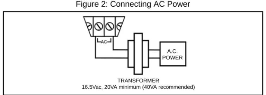
2.3.1 AC Power
Do not use any switch-controlled outlets to power the transformer. Use a 16.5Vac (50-60Hz) transformer with a minimum 20VA (40VA recommended) rating to provide sufficient AC power. UL/cUL listed systems require a Universal Model No. UB1640W plug-in transformer. Connect the transformer as shown in Figure 2.The power supply can provide a maximum of 1.1A for battery charge current.
Do not connect the transformer or the backup battery until all the wiring is completed. Figure 2: Connecting AC Power
2.3.2 Backup Battery
We recommend connecting a backup battery to power the control panel in case of power loss. UL/cUL installations require the use of a backup battery. Use a 12Vdc 4Ah/7Ah rechargeable acid/lead or gel cell battery. For UL/cUL installations use only a 7Ah battery. Connect the backup battery after applying the AC power as shown in Figure 3 on page 3. When installing the battery, verify proper polarity, as reversed connections will blow the battery fuse. Connect the red battery lead to the positive battery terminal, and the black battery lead to the negative battery terminal of the control panel.
Cold water pipe or grounding rod
Ground clamp
To metallic enclosure AWG# 14 single
conductor solid copper wire
For UL Installations (728 Ultra)
For UL installations, make sure that only the EARTH ground is connected.
Cold water pipe or grounding rod
Ground clamp
TRANSFORMER
16.5Vac, 20VA minimum (40VA recommended) A.C. POWER
Figure 3: Connecting the Backup Battery
2.3.3 Auxiliary Power Terminals
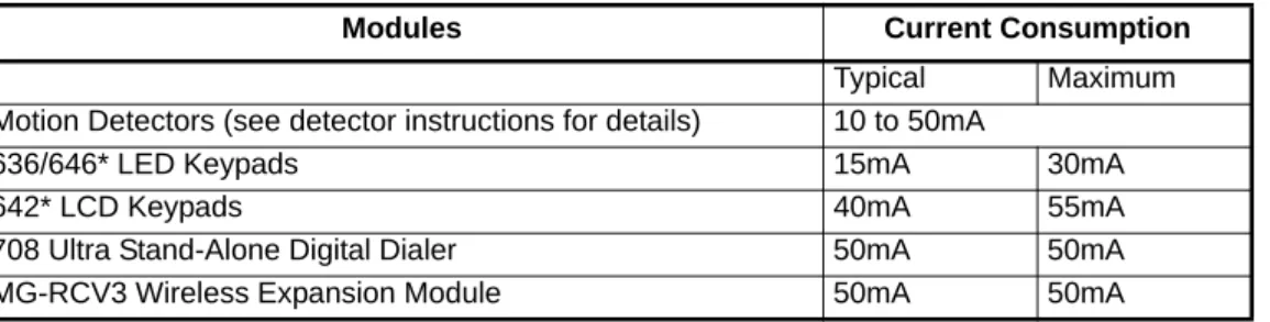
The AUX+ and AUX- terminals on the control panel can provide a maximum of 450mA (728 Ultra) or 500mA (738 Ultra) 12Vdc (200mA 12Vdc for 24Hr stand-by on UL/cUL installations). You can use the auxiliary power supply to power the motion detectors, keypads and other accessories in your security system. Their combined current consumption should not exceed 650mA (728 Ultra) or 700mA (738 Ultra). See Table 1 for current consumption levels. The auxiliary supply is microprocessor-protected against current overload and automatically shuts down if the current exceeds 650mA (728 Ultra) or 700mA (738 Ultra). Auxiliary power will resume once the overload condition is restored and within 1 to 60 seconds of performing the dynamic battery test.
* Do not use the 646 LED and 642 LCD keypads for UL installations. Both the 646 LED keypad and the 642 LCD keypad are not UL listed.
2.3.4 Battery Test
The control panel conducts a dynamic battery test under load every 60 seconds. If the battery is disconnected, or its capacity is too low, the [1] key in the trouble display mode will illuminate. Key [1] will also illuminate if the battery voltage drops to 10.5 volts or less when the control panel is running on the back-up battery (no AC). At 8.5 volts, the panel shuts down and all outputs close.
2.3.5 Keypad Function Test
We recommend conducting a power-up test on keypads installed far from the control panel. To do so, temporarily connect the keypads near the control panel and connect the transformer. After 10 seconds, begin entering random commands on the keypad and verify that the keypad beeps in response to these commands. Then open a zone to ensure that the keypad and the control panel are responding to these signals. If the keypad does not respond and indicator lights do not illuminate, verify that approximately 16Vac is present at the AC terminals. If AC is present, check the keypad wiring and verify that there isn't a short between the black and red keypad wires. If the keypad does not respond, please contact your local Paradox Distributor.
2.4
Telephone Line Connection
Connect the incoming telephone company wires into the TIP and RING connections of the control panel. Then run the wires from
T-1 and R-1 to the telephone system as shown in Figure 4. If the STATUS LED is always ON, the panel is using the phone line.
Figure 4: Telephone Line Connection Table 1: Current Consumption Table
Modules Current Consumption
Typical Maximum
Motion Detectors (see detector instructions for details) 10 to 50mA
636/646* LED Keypads 15mA 30mA
642* LCD Keypads 40mA 55mA
708 Ultra Stand-Alone Digital Dialer 50mA 50mA
MG-RCV3 Wireless Expansion Module 50mA 50mA
Backup battery 12Vdc 4Ah / 7Ah
UL / cUL 12Vdc 7Ah only
2.5
Bell/Siren Output
The BELL+ and BELL- terminals, power bells and/or other warning devices require a steady voltage output during an alarm. The bell output supplies 12Vdc upon alarm and can support one 20-watt siren or one 30-watt siren. The bell output is microprocessor-controlled and will automatically shut down if the current exceeds 3A. If the load on the bell terminals returns to normal, the processor will resume power to the bell terminals upon generation of another alarm. When connecting sirens (speakers with built-in siren drivers), please verify correct polarity. Connect the positive lead to the BELL+ terminal and the negative lead to the BELL- terminal of the control panel as shown in Figure 5.
Should the power supply and/or battery voltage level drop below a safe operational level during an alarm, the bell/siren output will be disconnected to allow the system to properly dispatch an alarm condition to the monitoring station. In this event, the system is designed to prevent the bell/siren output from activating until the backup battery capacity reaches 50%. This leaves more energy for the control panel’s power supply to rapidly charge the backup battery. The bell/siren output circuitry will then only reactivate after another alarm condition has occurred. Once this condition has been met, the bell/siren output will function normally. 2.5.1 Alarm Relay Outputs (738 Ultra; Optional)
The alarm relay output is a single pole 5A relay with double throw dry contacts that follows the bell/siren alarm output. If the Bell/Siren output is not being used, connect a 1k9 resistor across the BELL+ and BELL- terminals.
Figure 5: Bell/Siren Output Connection
2.6
Programmable Outputs (PGMs)
The 728 Ultra and 738 Ultra control panels include one (728 Ultra) or two (738 Ultra) fully programmable outputs (PGM). When a specific event or condition occurs in the system, a PGM can be used to reset smoke detectors, activate strobe lights, open or close garage doors and much more. The PGMs provide a maximum 50mA output. If the current draw on a PGM output exceeds 50mA, we recommend the use of a relay as show in Figure 6. The PGMs can be programmed to turn on and off for more than a thousand different events. For example, a PGM can open and close an automatic garage door by pressing keys [1] and [2] simultaneously on the keypad. For details on how to program the PGMs, refer to PGMs (Programmable Outputs) on page 35.
Figure 6: Connecting the PGM output
2.7
Keypad and Keyswitch Connections
Connect the four keypad connections labeled RED, BLACK, GREEN and YELLOW to the corresponding colour terminals on the control panel as indicated in Figure 7. Please note that on some keypads you may have to remove the back panel to make the connections. Connect the keyswitch to the GRN and BLK terminals of the control panel as shown in Figure 7. To enable this function, please refer to Arming Using a Keyswitch on page 33 and Keyswitch or Pushbutton Arming/Disarming on page 42 for more information on keyswitches.
Figure 7: Keypad and Keyswitch Connections
Low voltage door activation input
* PGM2 available only with 738 Ultra
Partial view of 728 Ultra
Keyswitch Partial view of
2.8
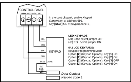
Keypad Zone Connections
Each keypad comes with one input terminal which allows you to connect one detector or door contact directly to the keypad.
Example: A door contact located at the entry point of an establishment can be wired directly to the input terminal of the entry point keypad instead of wiring the door contact all the way to the control panel.
Figure 8: Connecting One Keypad Zone
Regardless of the number of keypads in the system, the control panel supports a maximum of two keypad zones. The control panel will recognize these added zones as shown in Table 2 on page 6.
If using two keypad zones, one keypad must be defined as keypad zone 1 while the other must be defined as keypad zone 2 (see Figure 9 on page 5).
Example: A security installation is composed of five keypads. Of these five keypads only two can have their zone input terminals enabled (see Figure 9 on page 5). The other three keypads must have their zone input terminals disabled as described in Disabling 636 and 646* Keypad Zones on page 5 and Disabling 642* Keypad Zones on page 5.
Figure 9: Connecting Two Keypad Zones Using Two Keypads
Disabling 636 and 646* Keypad Zones
If the keypad zone input terminal is not being used, disable it by shorting the blue zone wire with the black COM wire of the keypad. Disabling 642* Keypad Zones
If the keypad zone input terminal is not being used, disable it by setting option [2] (Keypad Options) key [1] to OFF.
* Do not use the 646 LED and 642 LCD keypads for UL installations. Both the 646 LED keypad and the 642 LCD keypad are not UL listed.
LED KEYPADS:
(J1) Zone select jumper OFF (J2) EOL select jumper ON
642 LCD KEYPADS:
Keypad Programming Mode Option [2] (Keypad Options); Key [1] ON Option [2] (Keypad Options); Key [2] ON Option [2] (Keypad Options); Key [3] OFF Option [2] (Keypad Options); Key [4] ON In the control panel, enable Keypad
Supervision at address 090. Key[STAY] ON = Keypad Zone 1
Door Contact Keypad zone 1
KEYPAD ZONE 1:
LED Keypad: (J1) Zone select jumper OFF (J2) EOL select jumper ON 642 LCD Keypads: Keypad programming mode
Option [2] (Keypad Options) key [1] ON
Option [2] (Keypad Options) key [2] ON
Option [2] (Keypad Options) key [3] OFF
Option [2] (Keypad Options) key [4] ON
KEYPAD ZONE 2:
LED Keypad: (J1) Zone select jumper ON (J2) EOL select jumper ON 642 LCD Keypads: Keypad programming mode
Option [2] (Keypad Options) key [1] ON
Option [2] (Keypad Options) key [2] ON
Option [2] (Keypad Options) key [3] ON
Option [2] (Keypad Options) key [4] ON
In the control panel, enable keypad supervision at address 090: keys
[STAY] and [AWAY]/[FORCE] ON
Door Contact Keypad zone 1
Door Contact Keypad zone 2
2.9
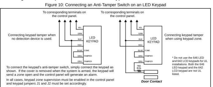
Connecting an Anti-Tamper Switch on an LED Keypad
Figure 10: Connecting an Anti-Tamper Switch on an LED Keypad
Once the keypad zones have been defined, you must enable Keypad Zone Supervision (see Keypad Zone 1 Supervision on page 30 and Keypad Zone 2 Supervision on page 30) in the control panel.
2.10
Single Zone Input Terminal Connections
The system hardware recognizes the following single zone input terminal connections. For more information on programming the options mentioned below, see Zone Definitions on page 25.
2.10.1 N.C. Contacts, Without EOL Resistor
If your security installation does not require tamper or wire fault detection, connect the detection devices and program the control panel as shown in Figure 11. This setup will communicate an open or closed zone to the control panel and display open zones on the keypad. Do not use devices with N.O. contacts in this setup, as this will cause the control panel to remain in alarm.
Figure 11: N.C. Contacts, without EOL Resistor Table 2: Keypad Zone Recognition Table If using an LED keypad, set the Zone Select Jumper (J1) on the back of the keypad: Zone Select Jumper J1 OFF = Keypad Zone 1
Zone Select Jumper J1 ON = Keypad Zone 2
If the Zone Select Jumper is changed, the control panel will only recognize the change when the keypad is disconnected and reconnected.
If using a 642 LCD Keypad, program the keypad definitions as follows:
Keypad Programming Mode, option [2] (Keypad Options); Key [1] ON = Keypad Zone Enabled Keypad Programming Mode, option [2] (Keypad Options); Key [2] ON = Requires 1k9 EOL Keypad Programming Mode, option [2] (Keypad Options); Key [3] OFF = Keypad Zone 1 Keypad Programming Mode, option [2] (Keypad Options); Key [3] ON = Keypad Zone 2
Keypad Programming Mode, option [2] (Keypad Options); Key [4] ON = Keypad Communication Supervision The control panel will display open keypad zones as follows:
ATZ disabled (728 Ultra) ATZ enabled (728 Ultra) ATZ disabled (738 Ultra) ATZ enabled (738 Ultra)
Keypad Zone 1 = Zone 5 Keypad Zone 1 = Zone 9 Keypad Zone 1 = Zone 9 Keypad Zone 1 = Zone 17 Keypad Zone 2 = Zone 6 Keypad Zone 2 = Zone 10 Keypad Zone 2 = Zone 10 Keypad Zone 2 = Zone 18
To connect the keypad’s anti-tamper switch, simply connect the keypad as shown. If the cover is removed when the system is armed, the keypad will send a zone open and the control panel will generate an alarm.
In all cases, keypad zone supervision must be enabled in the control panel and keypad jumpers J1 and J2 must be set accordingly.
To corresponding terminals on the control panel.
To corresponding terminals on the control panel.
Connecting keypad tamper when using keypad zone. Connecting keypad tamper when
no detection device is used.
Door Contact
* Do not use the 646 LED and 642 LCD keypads for UL installations. Both the 646 LED keypad and the 642 LCD keypad are not UL listed.
Address 088,[MEM] = ON (EOL resistor disabled)
[0] = OFF
[STAY] = OFF Address 090,[8] = OFF (ATZ disabled)
Tamper/Wire Fault disabled.
Control Panel Terminals
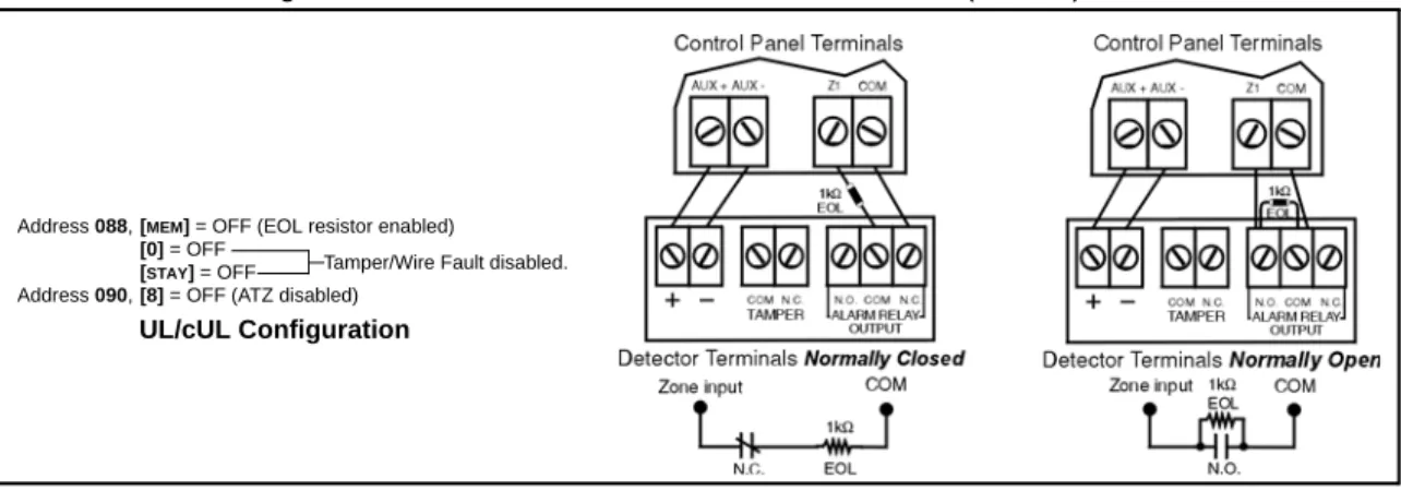
2.10.2 N.O. and N.C. Contacts, With EOL Resistor (UL/cUL)
If your security installation does not require tamper or wire fault recognition, but some detection devices use normally open contacts, connect all detection devices using a 1k9 end of line (EOL) resistor and program the control panel as shown in Figure 12. This setup will communicate an open or closed zone to the control panel and display open zones on the keypad.
Figure 12: N.O. and N.C. Contacts, with EOL Resistor (UL/cUL)
2.10.3 N.C. Contacts, Without EOL Resistor, With Tamper Recognition
If your security installation requires tamper recognition, all detection devices must use normally closed contacts. Connect the devices and program the control panel as shown in Figure 13. This setup will communicate an open or closed zone to the control panel and display open zones on the keypad. The control panel will also communicate any detected tampers (cuts) as per Tamper/Wire Fault Recognition Options on page 38.
Figure 13: N.C. Contacts, without EOL Resistor, with Tamper Recognition
2.10.4 N.C. Contacts, With EOL Resistor, With Tamper and Wire Fault Recognition (UL/cUL)
If your security installation requires tamper (cut) and wire fault (short) recognition, all detection devices must use normally closed contacts. Connect the devices and program the control panel as shown in Figure 14. This setup will communicate an open or closed zone to the control panel and display open zones on the keypad. The control panel will also communicate any detected tampers (cuts) and/or wire faults (short) as per Tamper/Wire Fault Recognition Options on page 38.
Figure 14: N.C. Contacts, with EOL Resistor, with Tamper and Wire Fault Recognition (UL/cUL)
2.11
Advanced Technology Zone (ATZ) Connections
Enabling the ATZ feature (see Advanced Technology Zoning (ATZ) on page 27) allows you install two detection devices per input terminal, therefore, doubling the zone capacity of the control panel. Advanced Technology Zoning is a software-oriented feature, so there is no need for extra modules. Simply install the devices as shown in Figures 16 to 19 on pages 8 to 9. The 728 Ultra and
Address 088,[MEM] = OFF (EOL resistor enabled)
[0] = OFF
[STAY] = OFF Address 090,[8] = OFF (ATZ disabled)
Tamper/Wire Fault disabled.
UL/cUL Configuration
Address 088,[MEM] = ON (EOL resistor disabled)
[0] =
[STAY] =
Address 090,[8] = OFF (ATZ disabled)
Refer to section 10.7 on page 38.
Control Panel Terminals
Detector Terminals
Address 088,[MEM] = OFF (EOL resistor enabled)
[0] =
[STAY] =
Address 090,[8] = OFF (ATZ disabled)
Refer to section 10.7 on page 38.
Control Panel Terminals
738 Ultra employ two ways of wiring ATZ connections: ATZ series connections and ATZ parallel connections. The control panel will recognize the installed devices as shown in Figure 15. The extra zones function exactly like any other zone displaying zone status on the keypad and sending separate alarm codes for each zone. For more information on programming the options mentioned in the following sections, refer to see Zone Definitions on page 25.
Figure 15: Zone Recognition with ATZ Enabled
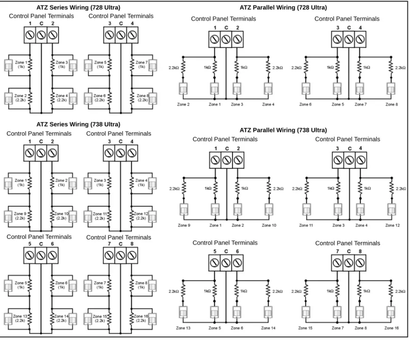
2.11.1 N.C. Contacts, Without EOL Resistor, ATZ Series
If your security installation does not require tamper or wire fault recognition, but you are using the ATZ feature, connect the detection devices and program the control panel as shown in Figure 16. Do not use devices with normally open contacts, as this will cause the system to remain in alarm. This setup will communicate the status of each device to the control panel (see Figure 15 on page 8) and display open zones on the keypad.
Figure 16: N.C. Contacts, without EOL Resistor
Control Panel Terminals Control Panel Terminals Control Panel Terminals Control Panel Terminals
Control Panel Terminals Control Panel Terminals
Control Panel Terminals Control Panel Terminals ATZ Series Wiring (728 Ultra) ATZ Parallel Wiring (728 Ultra)
ATZ Series Wiring (738 Ultra)
ATZ Parallel Wiring (738 Ultra)
Control Panel Terminals Control Panel Terminals Control Panel Terminals Control Panel Terminals
Address 088,[MEM] = ON (EOL resistor disabled)
[0] = OFF
[STAY] = OFF
Address 090,[7] = OFF (ATZ wiring in series)
[8] = ON (ATZ enabled)
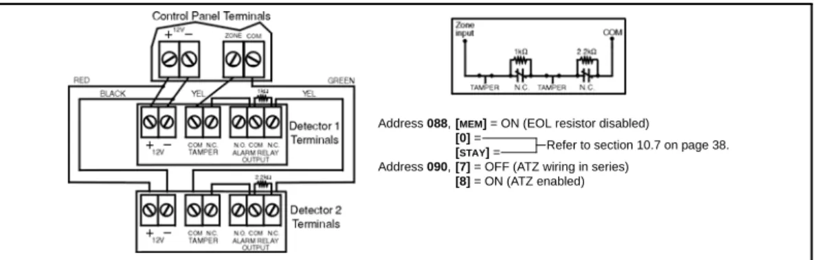
2.11.2 N.C. Contacts, Without EOL Resistor, With Tamper Recognition, ATZ Series
If your security installation requires tamper recognition and you are using the ATZ feature, connect the detection devices and program the control panel as shown in Figure 17. Do not use devices with normally open contacts, as this will cause the zone to remain open. This setup will communicate the status of each zone to the control panel (see Figure 15 on page 8) and display open zones on the keypad. The control panel will also communicate any detected tampers (cuts) on the system as per Tamper/Wire Fault Recognition Options on page 38.
Figure 17: N.C. Contacts, without EOL Resistor, with Tamper Recognition
2.11.3 N.C. Contacts, With EOL Resistor, With Tamper & Wire Fault Recognition (UL/cUL), ATZ Series If your system requires tamper (cut) and wire fault (short) recognition, connect two detection devices to one input terminal with a 1k9 end of line (EOL) resistor and program the control panel as shown in Figure 18. Do not use devices with normally open contacts, because this will cause the zone to remain open. This setup will communicate the status of each zone to the control panel (see Figure 18) and display open zones on the keypad. Any tampers (cuts) and/or wire fault (shorts) detected on the system are communicated as per Tamper/Wire Fault Recognition Options on page 38.
Figure 18: N.C. Contacts, with EOL Resistor, with Tamper and Wire Fault Recognition (UL/cUL)
2.11.4 N.C. Contacts, With ATZ Parallel Wiring
If your security installation does not require tamper or wire fault recognition, but requires the connection of two detection devices to one input to be in parallel, connect the devices and program the control panel as shown in ATZ Parallel Wiring on page 9. Do not use devices with normally open contacts as this will cause the zone to remain open. This setup will communicate the status of each zone to the control panel (see Figure 19 on page 9) and display open zones on the keypad. For more information, see ATZ Parallel Wiring on page 27.
Figure 19: ATZ Parallel Wiring
Address 090, key [7] (see ATZ Parallel Wiring on page 27) must be ON in order to connect the zones in parallel.
Address 088,[MEM] = ON (EOL resistor disabled)
[0] =
[STAY] =
Address 090,[7] = OFF (ATZ wiring in series)
[8] = ON (ATZ enabled)
Refer to section 10.7 on page 38.
Address 088,[MEM] = OFF (EOL resistor enabled)
[0] =
[STAY] =
Address 090,[7] = OFF (ATZ) wiring in series)
[8] = ON (ATZ enabled)
Refer to section 10.7 on page 38.
Address 088,[0] = OFF
[STAY] = OFF
Address 090,[7] = ON (ATZ wiring in parallel)
[8] = ON (ATZ enabled)
2.12
Fire Circuit
If your security installation requires the use of smoke detectors, define zone 3 as a 24Hr fire zone. When zone 3 is defined as 24Hr, it becomes a 4-wire smoke detector fire zone (2-wire smoke detector support must be disabled, address 086 key [BYP] = OFF). If using 2-wire smoke detectors and ATZ is enabled, zone 3 can be defined as 24Hr (728 Ultra only). Please refer to 24Hr and 4-Wire Smoke Detector Fire Zones on page 28.
2.12.1 4-Wire Smoke Detector Connections (Standard Installation)
Connect the 4-wire smoke detectors to zone 3 as shown in Figure 20. Note that a fire zone must use a 1k9 EOL resistor. If there is a line short or if the smoke detector becomes active, whether the system is armed or disarmed, the control panel will generate an alarm. If the line is open, the control panel will send a fire loop trouble report to the monitoring station and the trouble indicator ([STAY] key) will illuminate or a trouble will appear in the keypad’s trouble display.
All smoke detectors must be connected using a daisy chain configuration.
2.12.2 4-Wire Smoke Detector Connections (UL/cUL Installation)
For UL/cUL installations, use a 4-wire, latching, smoke detector (System Sensor model 2112/24D). To supervise the power supply, install an end of line relay (Model MR3). Connect the smoke detectors and relay as shown in Figure 21. In the event that power is interrupted, the relay will generate a fire trouble report (see 24Hr and 4-Wire Smoke Detector Fire Zones on page 28).
To reset (unlatch) the smoke detectors after an alarm, momentarily interrupt power to the detectors. To do so, verify that the negative (-) of the smoke detectors is connected to a PGM. Set the PGM for Timed N.C. (normally closed), and program the PGM to open when any two keys on the keypad are pressed simultaneously. For more information on programming the PGM, see PGMs (Programmable Outputs) on page 35.
Example: To program the PGM to conduct a 30-second smoke detector reset when the [CLEAR] and [ENTER] keys are pressed at the same time (see PGMs (Programmable Outputs) on page 35):
Address 039 = [BYP][2ND] Address 042 = [2ND] [6] Address 040 = [5] [0] Address 056 = [0] [3] [0]
All smoke detectors must be connected using a daisy chain configuration.
2.12.3 2-Wire Smoke Detector Connections
Connect the 2-wire smoke detectors to input 3 as shown in Figure 22. Note that a fire zone must use a 1k9 EOL resistor. If there is a line short or if the smoke detector becomes active, whether the system is armed or disarmed, the control panel will generate an alarm. If the line is open the control panel will send a fire loop trouble report to the monitoring station and the trouble indicator ([STAY] key) will illuminate or a trouble will appear in the keypad’s trouble display. With the 728 Ultra, when ATZ is disabled, the 2-wire smoke detector will be
connected to zone 3 (which is assigned to input 3). When ATZ is enabled, the 2-wire smoke detector will be connected to zone 5 (which is assigned to input 3 as shown in Figure 15 on page 8; 728 Ultra only). Zone 4 (zone 11 for 738 Ultra) will be disabled automatically to prevent the control panel from generating a “fire loop” trouble. Enable address 086, key [BYP] to configure the control panel to recognize the 2-wire smoke detector connected to input 3.
To conduct a 30-second reset, press and hold the [CLEAR] and [ENTER] keys on any keypad for 3 seconds.
All smoke detectors must be connected using a daisy chain configuration.
The 728 Ultra and 738 Ultra control panels support a maximum of five 2-wire smoke detectors. UL Warnings. For UL/cUL installations:
- The operating voltage of the fire circuit must be between 11 to 12Vdc. - Use only the Hochicki model SLR 835BH-2 2-wire smoke detector.
- 2-wire smoke detectors of different models other than the Hochicki model are not to be used.
2.13
Serial Output Connector
The four-pin Serial Output Connector is used to connect additional external devices to the control panel. To use the output connector, the PGM (PGM1 for 738 Ultra) must be disabled. To disable the PGM, program [2ND][2ND] into addresses 039, 040 and 042 (addresses 040 and 042 for 738 Ultra). For serial output connector specifications, refer to Specifications on page 1.
Figure 20
Figure 21
2.14
Status LED
The green STATUS LED is used to show the user what the status of the control panel is. • If the LED flashes once every second, operation is normal.
• If the LED is ON 1 second and OFF 1 second, there is a trouble in the system. • If the LED is always ON, the panel is using the phone line.
• If the LED flashes rapidly for 4 seconds after power-up, the installer lock is enabled.
Part 3: Access Codes
3.1
Installer Code
Streamline - Section 00 D Hex Programming - Addresses 000 to 002 Default: 282828 for 728 Ultra; 383838 for 738 Ultra
Only the Installer code allows you to program all control panel settings, except the Master and user codes. To program any setting in the control panel you must enter the programming mode by pressing the [ENTER] key followed by the Installer code. The Installer code contains six digits and each digit can be any value from 0 to 9. Although the control panel can accept 4-digit codes, when programming the Installer code, always enter six digits. To change the Installer code press:
[ENTER] + Installer code + [0] [0] [0] + First 2 digits + [0] [0] [1] + Next 2 digits + [0] [0] [2] + Final 2 digits + [ENTER]
3.2
Master and User Codes
Default Master Code: 474747
You cannot use the Installer code to program the Master and user codes. Only the Master code and User code 1 can program these access codes (see Programming Master and User Codes on page 40).
3.3
User/Access Code Length
Feature Select Programming D Address 088; Key [9] Default: 6-digit Access Codes
When programming user codes, an option for either 4-digit or 6-digit access codes can be programmed. When the 4-digit option is selected, entering a 4-digit code will allow the person access. Using the 6-digit option, entering 6 digits is required to allow access. Key [9] OFF: 6-digit Access codes
Key [9] ON: 4-digit Access codes
[ENTER] + Installer code + [0] [8] [8] + [9] ON/OFF + [ENTER] twice
3.4
Duress
Feature Select Programming D Address 090; Key [0] Default: Duress Disabled
When unwillingly forced to disarm a system, a user can enter User code #48 instead of their usual code. This code will disarm the system and send a silent alert (Duress code) to the monitoring station.
Key [0] OFF: Duress Disabled Key [0] ON: Duress Enabled
[ENTER] + Installer code + [0] [9] [0] + [0] ON/OFF + [ENTER] twice
3.5
Installer Lock
Decimal Programming D Address 058 Default: Address Empty
Program 147 into address 058 to lock all programming. When the installer lock is enabled, the STATUS LED will flash rapidly and the dialer relay will make a clicking noise (made by the relay opening and closing) for 4 seconds during power up. Hence, performing a hardware reset (see Power Down Reset on page 39) will not affect the current settings. To remove the installer lock, enter any value besides 147.
[ENTER] + Installer code + [0] [5] [8] + [1] [4] [7] + [ENTER]
3.6
Master Code Lock
Feature Select Programming D Address 090; Key [BYP] Default: Disabled
This feature locks both the Master code and User code 1. With address 090 key [BYP] enabled, the Master code and User code 1 cannot be changed or deleted. With this feature enabled, the Master code and User code 1 can only be changed or deleted through Espload or by disabling this feature.
Part 4: Programming Methods
The 728 Ultra and 738 Ultra control panels can be programmed using either the keypad or the Espload Software (V3.0 or higher for 728 Ultra, and V3.4 or higher for 738 Ultra). We highly recommend programming the control panels using the Espload Software, as it simplifies the process and reduces the potential for data entry errors.
4.1
Espload Software
With the Espload Software (V3.0 or higher for 728 Ultra, and V3.4 or higher for 738 Ultra), you can program the 728 Ultra and 738 Ultra control panels remotely via modem or locally using an ADP-1 adapter. The advanced Espload software can execute fast uploads or downloads and provides many powerful features. These include a comprehensive monitoring mode to oversee all panel activity, a scheduler to initiate pre-programmed tasks at set intervals, and a batch mode to carry out pre-programmed tasks following a call from the control panel. Using Espload there is no limit to the number of account files or panel defaults created and you can assign thousands of programming combinations to the PGM outputs. Espload can also be converted to the language of your choice. Contact your local Paradox Distributor for your free copy of the Espload software.
4.2
Keypad
When programming, use the 728 Ultra & 738 Ultra System Programming Guide to keep track of which addresses were
programmed and how. Before you begin programming the control panel, we recommend that you read Parts 5 through 11 of this manual in order to give you a good understanding of the control panel and its many features. When programming with the keypad, certain addresses are programmed using different methods. These methods are described in detail below. Each section in this manual will reference the appropriate programming method.
4.2.1 Hex Programming
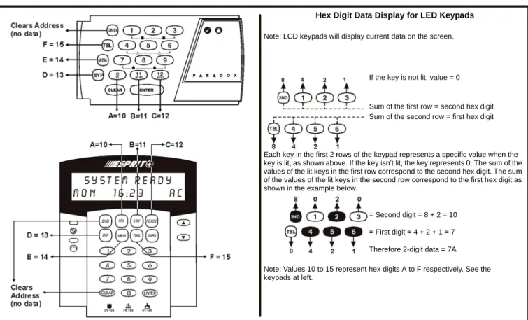
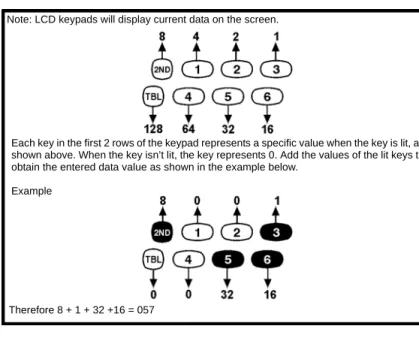
Addresses 000 to 043 and 300 to 527 are programmed using the Hex Programming method. In this mode, you can enter any hex-digit from 0 to F where keys [1] to [9] represent digits 1 to 9 respectively; the other keys represent hex-digits A to F as shown in Figure 23. To program using the Hex Programming method:
1. Press [ENTER] + Installer code. The [ENTER] key will flash indicating you are in programming mode (LED keypad only). 2. Enter the desired 3-digit address. The keypad will display the 2-digit data currently saved at this address as
described in Figure 23.
3. Enter 2-digit data. After entering data you do not need to press ENTER, the software will automatically save the data into the selected address.
4. Return to step 2 to continue programming or press [CLEAR] to exit programming mode. Figure 23: Hex Programming
Hex Digit Data Display for LED Keypads Note: LCD keypads will display current data on the screen.
Therefore 2-digit data = 7A = First digit = 4 + 2 + 1 = 7 = Second digit = 8 + 2 = 10
Note: Values 10 to 15 represent hex digits A to F respectively. See the keypads at left.
Each key in the first 2 rows of the keypad represents a specific value when the key is lit, as shown above. If the key isn’t lit, the key represents 0. The sum of the values of the lit keys in the first row correspond to the second hex digit. The sum of the values of the lit keys in the second row correspond to the first hex digit as shown in the example below.
Sum of the second row = first hex digit Sum of the first row = second hex digit If the key is not lit, value = 0
4.2.2 Hex Streamlined Section Programming
This is an alternate method to Hex Programming. The addresses (000 to 043 and 300 to 527) programmed in the Hex Programming method are grouped into 68 sections where each section contains four addresses (i.e. section 00 = addresses 000 to 003). Using this method allows you to program 8 digits (4 addresses) without having to exit and re-enter addresses. When re-entering the final digit, the software will automatically advance to the next section.
Example: If you complete the 728 Ultra & 738 Ultra System Programming Guide with the desired data, you can program the 68 sections by entering all of the digits without pressing [ENTER] or entering any other addresses. This greatly reduces programming time.
The keypad will not display the current data in the Hex Streamlined Programming method.
To program using the Hex Streamlined Section method:
1. Press [ENTER] + Installer code + [7]. The [ENTER] and [2ND] keys will flash to indicate you are in streamlined programming mode (LED keypad only).
2. Enter 2-digit section (00 to 67). The [ENTER] key will remain on and the [2ND] key will turn off (LED keypad only). 3. Enter 8-digit data to program the section. The keypad will beep to indicate that the section has been programmed,
data is saved and the software has advanced to the next section.
4. Return to step 3 to continue programming or press [CLEAR] to exit programming mode. 4.2.3 Decimal Programming
Addresses 044 to 061 are programmed using the Decimal Programming method. Values entered must contain three digits from 000 to 255. To program using the Decimal Programming method: 1. Press [ENTER] + Installer code. The
[ENTER] key will flash to indicate you are in programming mode (LED keypad only).
2. Enter 3-digit address (044 to 061). The keypad will now display the current 3-digit data currently saved at this address as described in Figure 24. 3. Enter 3-digit data (decimal) value. After
entering data you do not need to press [ENTER], the software will automatically save the data into the selected address.
4. Return to step 2 to continue
programming or press [CLEAR] to exit programming mode.
4.2.4 Feature Select Programming
Addresses 062 to 126 are programmed using the Feature Select Programming method. In this method, every key in each address on the keypad represents an option or feature. Pressing a key will display it on the keypad and pressing it again will extinguish the key. The ON/OFF status of each key determines the selected feature. To program using the Feature Select Programming method:
1. Press [ENTER] + Installer code. The [ENTER] key will flash to indicate you are in programming mode.
2. Enter 3-digit address (062 to 126). After entering the address, the keypad will display the feature selection status. The ON/OFF status of the keys determines the selected features as described in the 728 Ultra & 738 Ultra System Programming Guide and in the appropriate sections of this manual. Turn the keys ON/OFF by pressing the appropriate key until the desired options are set. Then press the [ENTER] key to accept, there will be a confirmation beep indicating the options have been accepted. The [ENTER] key will flash to indicate that the software is awaiting the next address entry (LED keypad only).
3. Return to step 2 to continue programming or press [CLEAR] to exit programming mode.
Figure 24: Decimal Display For LED Keypads
Note: LCD keypads will display current data on the screen.
Each key in the first 2 rows of the keypad represents a specific value when the key is lit, as shown above. When the key isn’t lit, the key represents 0. Add the values of the lit keys to obtain the entered data value as shown in the example below.
Example
Part 5: Panel Settings for Espload
5.1
Panel Answer Options
Streamline - Section 00 D Hex Programming - Address 003
Default: Answering Machine Override Disabled; Number of Rings = 08
The following two options will define how the control panels answer an incoming call from a computer using the Espload software. In order for the Espload software to remotely communicate with the control panel, call the installation site twice using the Espload Software. To do so, program the first digit in address 003 with any value from 1 to F (see Table 3). This value represents the length of the delay period the control panel will wait between the first and second call. Using the Espload software, call the installation site and on the second ring press [ENTER] on the keyboard to hang-up. After hanging up, the Espload software will wait 10 seconds before calling the installation site back. If the installation site is called back within the programmed delay period, the control panel will override the answering machine or service by picking up on the first ring. To disable this option program [2ND] or [1] as the first digit in address 003.
Example: A security installation is using an answering machine set to answer after 3 rings, the first digit at address 003 has been programmed with 5 (40 sec.) and the second digit has been programmed with 8. When you call the installation site with the Espload software the first time, wait two rings and press [ENTER] on the keyboard. The Espload software will wait 10 seconds before calling the installation site back. If the second call is made within 40 seconds, the panel will pick up the line on the first ring. If it takes more than 40 seconds, the panel will not answer on the first ring and the answering machine will answer after three rings.
[ENTER] + Installer code + [0] [0] [3] + 1st digit + 2nd digit (01 to 15 rings) + [ENTER]
The second digit represents the number of rings the control panel will wait before picking up the line. If the line is not answered after the number of re-programmed rings, the control panel will answer the call. Note the control panel resets the ring counter every 64 seconds. Therefore, if someone or an answering machine answers a call before the number of pre-programmed rings has elapsed, the control panel will keep the number of rings in memory for 64 seconds. If you hang-up and call the installation site back within 64 seconds, the control panel will continue to count the number of rings from the first call. After reaching the total number of rings, the control panel will answer the call. The number of rings can be set from 1 to 15 by programming the second digit at address 003 with any hex-digit from 1 to F. Program the second digit with [2ND] to disable this option.
Example: Address 003 = [2ND][8]. Using the Espload software, you call an installation site where there is no answering machine or service and no one is home. Since there is no one to answer the telephone call, the control panel will pick-up the line on the eighth ring. If someone happens to be home and answers the telephone after three rings, the control panel will keep the three rings in memory for 64 seconds. If you hang-up and call back the installation site within 64 seconds the control panel will answer the call on the fifth ring. If you call back after 64 seconds the ring counter will have been reset and the control panel will answer the call on the eighth ring.
If you program four rings or less, the control panel will always reset the “ring” counter.
5.2
Panel Identifier
Streamline - Section 01 D Hex Programming - Addresses 004 and 005
This four-digit code identifies the control panel to the Espload software before initiating upload. Program the same 4-digit code into the control panel and the Espload software before attempting to establish communication. If the codes do not match, the control panel will not establish communication. Enter any hex digits from 0 to F.
[ENTER] + Installer code + [0] [0] [4] + First 2 digits + [0] [0] [5] + Final 2 digits + [ENTER]
5.3
PC Password
Streamline - Section 01 D Hex Programming - Addresses 006 and 007
This four-digit download password identifies the PC to the panel, before beginning the download process. Enter the same password into the Espload software and the control panel. If the passwords are not the same, Espload will not establish communication. Enter any hex digits from 0 to F.
[ENTER] + Installer code + [0] [0] [6] + First 2 digits + [0] [0] [7] + Final 2 digits + [ENTER] Table 3: Answering Machine Override Options [2ND] or [1] = Answering Machine Override disabled
[2] = 16 seconds [4] = 32 seconds [6] = 48 seconds [8] to [F] = 60 seconds [3] = 24 seconds [5] = 40 seconds [7] = 56 seconds
5.4
Computer Telephone Number
Streamline Section 02 and 03 D Hex Programming - Address 008 to 015
The control panel will dial this telephone number when trying to initiate communication with the PC (see Call Espload below). There is no default telephone number and you can enter any number from 0 to 9 up to a maximum of 16 digits. If you would like to enter any special keys or functions, refer to Table 5 on page 18. If the telephone number contains less than 16 digits, press the [TBL]/[TRBL] key to indicate the end of the telephone number.
[ENTER] + Installer code + [7] + [0] [2] + Telephone Number (if less than 16 digits press [TBL]/[TRBL]) + [ENTER]
5.5
Call Espload
Key Access Programming D key [TBL]/[TRBL]
The control panel will dial the telephone number entered at addresses 008 to 015 (see Computer Telephone Number above) in order to communicate with the Espload software. The control panel and the computer will verify that the Panel Identifier and the PC Password match before establishing communication (see Panel Identifier and PC Password on page 14). Espload must be set in “Wait For Call” mode.
Press [ENTER] + (Installer, Master or User code 1) + [TBL]/[TRBL]
5.6
Answer Espload
Key Access Programming D Key [AWAY]/[FORCE]
By entering the code sequence listed below, you can manually force the control panel to answer any incoming calls from the Espload software. This option can also be used to perform an on-site upload/download by connecting your computer directly to the control panel using an ADP-1 line adapter and manually answering Espload from the control panel. In Espload go to:
Main Menu D Program Setup D Modem and Printer Configuration
Set "Dialing Condition" to "Blind Dial". Program the panel telephone number in Espload and follow the instructions on the ADP-1 adapter. When the computer has dialed, press:
[ENTER] + (Installer, Master or User code 1) + [AWAY]/[FORCE]
5.7
Cancel Communication
Key Access Programming D Key [STAY]
Use the Installer code to cancel all communication and erase any unreported events in the buffer until the next reportable event. Use the Master or User code 1 to cancel communication attempts with Espload.
[ENTER] + (Installer, Master and User code 1) + [STAY]
5.8
Call Back
Feature Select Programming D Address 086; Key [4] Default: Call Back Disabled
For additional security, when a PC using the Espload software attempts to communicate with the control panel, the control panel can hang-up and call the PC back in order to re-verify identification codes and re-establish communication. When the control panel answers the call, it will verify if the Panel ID and PC Passwords match and if they do, the control panel will hang-up and call the Espload software back. The Espload software will automatically go into "wait for dial tone", ready to answer when the control panel calls back. Please note the Computer Telephone Number (see Computer Telephone Number above) must be programmed in order to use the Call Back feature.
Key [4] OFF: Call Back Disabled Key [4] ON: Call Back Enabled
[ENTER] + Installer code + [0] [8] [6] + [4] ON/OFF + [ENTER] twice
5.9
Automatic Event Buffer Transmission
Feature Select Programming D Address 088; Key [2ND] Default: Automatic Event Buffer Transmission Disabled
When the event buffer reaches 50% capacity, the control panel will make two attempts to establish communication with a PC. The control panel will call the Computer Telephone Number (see Computer Telephone Number above) programmed at
addresses 008 to 015. The Espload software must be in "wait for dial tone" mode. When the system establishes communication, it will upload the contents of the event buffer to the Espload software. If communication is interrupted before transmission of the complete contents of the buffer, or if after two attempts, communication is not established, the system will wait until the event buffer is full before attempting to re-communicate with Espload. When the Event Buffer is full, each subsequent new event will erase the oldest event in the buffer.
Key [2ND] OFF: Automatic Event Buffer Transmission Disabled Key [2ND] ON: Automatic Event Buffer Transmission Enabled [ENTER] + Installer code + [0] [8] [8] + [2ND] ON/OFF + [ENTER] twice
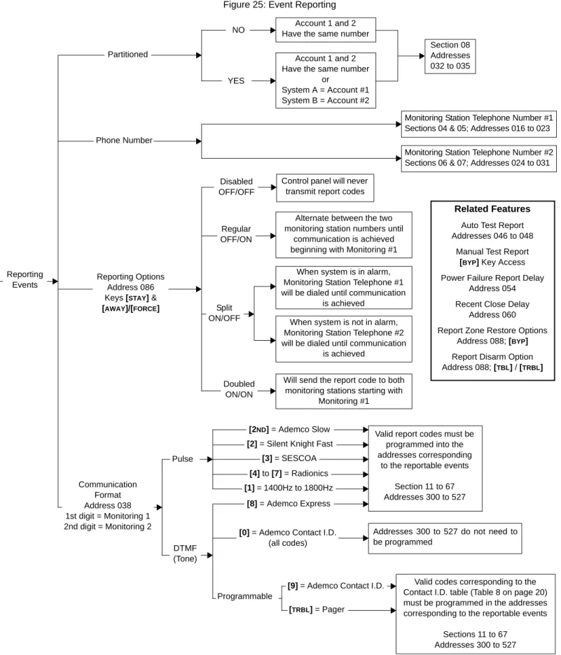
Part 6: Event Reporting
Figure 25: Event ReportingAccount 1 and 2 Have the same number
Account 1 and 2 Have the same number
or
System A = Account #1 System B = Account #2
Section 08 Addresses 032 to 035
Monitoring Station Telephone Number #1 Sections 04 & 05; Addresses 016 to 023 Monitoring Station Telephone Number #2 Sections 06 & 07; Addresses 024 to 031 Control panel will never
transmit report codes Alternate between the two monitoring station numbers until
communication is achieved beginning with Monitoring #1 When system is in alarm, Monitoring Station Telephone #1 will be dialed until communication
is achieved When system is not in alarm, Monitoring Station Telephone #2 will be dialed until communication
is achieved
Will send the report code to both monitoring stations starting with
Monitoring #1
Related Features Auto Test Report Addresses 046 to 048
Manual Test Report [BYP] Key Access Power Failure Report Delay
Address 054 Recent Close Delay
Address 060 Report Zone Restore Options
Address 088; [BYP] Report Disarm Option Address 088; [TBL] / [TRBL]
Valid report codes must be programmed into the addresses corresponding
to the reportable events Section 11 to 67 Addresses 300 to 527
Addresses 300 to 527 do not need to be programmed
Valid codes corresponding to the Contact I.D. table (Table 8 on page 20) must be programmed in the addresses corresponding to the reportable events
Sections 11 to 67 Addresses 300 to 527 NO YES Disabled OFF/OFF Regular OFF/ON Split ON/OFF Doubled ON/ON
[2ND] = Ademco Slow [2] = Silent Knight Fast
[3] = SESCOA [4] to [7] = Radionics [1] = 1400Hz to 1800Hz
[8] = Ademco Express
[0] = Ademco Contact I.D. (all codes)
[9] = Ademco Contact I.D. Programmable
[TRBL] = Pager Pulse DTMF (Tone) Communication Format Address 038 1st digit = Monitoring 1 2nd digit = Monitoring 2
Reporting Options Address 086 Keys [STAY] & [AWAY]/[FORCE] Phone Number
Partitioned
Reporting Events
6.1
Reporting Options
Feature Select Programming D Address 086; Keys [STAY] and [AWAY]/[FORCE] Default: Reporting Disabled
When a specific event occurs in the system, the control panel will attempt to report the appropriate event code (if programmed) to the monitoring station. The four available Reporting Options described in Table 4, define where the event codes are reported. In order to establish communication with the monitoring station, the control panel will first access a telephone line and wait a maximum of 8 seconds for a dial tone. If a dial tone is recognized, or if after 8 seconds there is no dial tone, the control panel will dial the appropriate Monitoring Station Telephone Number (MSTN) as defined by the Reporting Options listed in Table 4. If communication is established, the control panel will transmit the events in the event buffer to the monitoring station. If communication fails during transmission, the control panel will dial the next MSTN, as defined by the reporting options listed below, and report only those events not reported during the interrupted attempt. For more information see Reporting Event Codes
on page 22.
[ENTER] + Installer code + [0] [8] [6] + [STAY] and [AWAY]/[FORCE]ON/OFF + [ENTER]
6.1.1 Reporting Disabled
The control panel will never transmit any event codes to the monitoring station. 6.1.2 Regular Reporting
Using Regular reporting, the event codes are reported to the monitoring station using either telephone number 1 or 2. The control panel will begin by dialing Monitoring Station Telephone Number 1 (MSTN1). If communication fails, the dialer will hang up, wait a predetermined period and dial MSTN2. This sequence will repeat 4 times, switching back and forth between the 1st and 2nd number (see Figure 26 on page 18) until communication is established. After eight unsuccessful attempts, the redial sequence ends and a "communicator report failure" will appear in the keypad's trouble display (key [7] ON). When the next event occurs (reportable or non-reportable), the control panel will begin the dialing sequence again.
6.1.3 Split Reporting
When the system is not in alarm, the control panel will report all Event codes to Monitoring Station Telephone 2 (MSTN2). If communication fails, the dialer will hang-up, wait a predetermined period and dial the number again. The control panel will dial the number eight times until communication is established (see Figure 26 on page 18). After eight unsuccessful attempts, the redial sequence ends and a "communicator report failure" will appear in the keypad's trouble display (key [7] ON). When the next event occurs (reportable or non-reportable), the control panel will begin the dialing sequence again.
When the system is in alarm, the control panel will report all Event codes to MSTN1. Any ongoing communication (upload/download or reporting to Telephone 2) will stop immediately and the panel will dial Telephone 1. If
communication fails, the dialer will hang-up, wait a predetermined period and dial the number again. The control panel will dial the number eight times until communication is established (see Figure 26 on page 18). After eight
unsuccessful attempts, the redial sequence ends and a "communicator report failure" will appear in the keypad's trouble display (key [7] ON). When the next event occurs (reportable or non-reportable), the control panel will begin the dialing sequence again.
6.1.4 Double Reporting
In double reporting, the control panel will report each event code to both Monitoring Station Telephone Numbers (MSTN). The control panel will begin by attempting communication with MSTN1 and if communication fails, the dialer will hang-up, wait a predetermined period and dial the number again. The control panel will dial the number eight times until communication is established (see Figure 26 on page 18). After eight unsuccessful attempts, the redial sequence ends and a "communicator report failure" will appear in the keypad's trouble display (key [7] ON). If communication has been established and the event codes transmitted, or if after eight attempts communication has not been established, the control panel will report the same Event codes to MSTN2.
Table 4: Reporting Options
Key [STAY] Key [AWAY]/[FORCE] Reporting Feature
OFF OFF Reporting Disabled
OFF ON Regular Reporting
ON OFF Split Reporting
Figure 26: Reporting Options
6.2
Monitoring Station Telephone Number 1 (MSTN1)
Streamline - Section 04 and 05 D Hex Programming - Addresses 016 to 023
The control panel will dial the programmed telephone number when reporting an event code to the monitoring station computer (see Reporting Options on page 17). For example, if the alarm system is armed and a zone with a motion detector opens, the control panel may dial the telephone number in order to send the programmed event code to the monitoring station computer. There is no default telephone number and you can enter any number from 0 to 9 up to a maximum of 16 digits. If you would like to enter any special keys or functions, refer to Table 5 below. If the telephone number contains less than 16 digits, press the [TBL]/[TRBL] key to indicate the end of the telephone number.
[ENTER] + Installer code + [7] + [0] [4] + MSTN1 + [ENTER] or [TBL]/[TRBL] if number is less than 16 digits
6.3
Monitoring Station Telephone Number 2 (MSTN2)
Streamline - Section 06 and 07 D Hex Programming - Addresses 024 to 031
The control panel can communicate with two monitoring station numbers. The control panel may at times dial the second number depending on the selected Reporting Options (see Reporting Options on page 17). If the monitoring station does not have a second number, you must enter the same number as the first. There is no default telephone number and you can enter any number from 0 to 9 up to a maximum of 16 digits. If you would like to enter any special keys or functions refer to Table 5. If the telephone number contains less than 16 digits, press the [TBL]/[TRBL] key to indicate the end of the telephone number.
[ENTER] + Installer code + [7] + [0] [6] + MSTN2+ [ENTER] or [TBL]/[TRBL] if number is less than 16 digits
Both monitoring station telephone numbers must be programmed in order for event reporting to function properly.
Table 5: Telephone Number Special Instruction Enter special instructions in the telephone numbers using these keys:
[0] = the number “0” [BYP] = switch from pulse to tone while dialing
[STAY] = * [MEM] = pause 4 seconds
[AWAY]/[FORCE] = # [TBL]/[TRBL] = end of telephone number MSTN = Monitoring Station Telephone Number
The following set of timing diagrams represents the dialing sequence of each of the three reporting options. Regular Reporting:
Split Reporting: All codes are sent to MSTN2 except when the system is in alarm, codes will be sent to MSTN1.
Double Reporting: All codes are sent to both monitoring station telephone numbers.
Once communication is established and the events have been uploaded, the control panel will begin dialing MSTN2.
System not in alarm:
System in alarm:
OR
AND
Dialing Disconnected
Dialing Disconnected
Dialing Disconnected
Dialing Disconnected
Dialing Disconnected
Sequence ends and keypad displays “communication failure” trouble key [7].
Sequence ends and keypad displays “communication failure” trouble key [7].
Sequence ends and keypad displays “communication failure” trouble key [7].
Sequence ends and keypad displays “communication failure” trouble key [7].
Continues by dialing MSTN2
Sequence ends and keypad displays “communication failure” trouble key [7].