6
I
January 2018
The Analysis of SMAW Parameters for
Optimization of Mechanical Properties using
Taguchi Method on DSS Material
A.Balaram Naik 1, A.Chennakesava Reddy 2, S.Raja Srikaran Rao 3
1
Asst professor of Dept. of Mechanical Engineering, JNTUH College of Engineering, Hyderabad, 2
Professor Dept. of Mechanical Engineering, JNTUH College of Engineering, Hyderabad, Kukatpally 3
MTECH student of Dept. of Mechanical Engineering, JNTUH College of Engineering, Hyderabad,
Abstract: Welding input parameters play a very significant role in determining the quality of a weld joint. The joint quality can be defined in terms of mechanical properties such as ultimate tensile strength, hardness and toughness. Generally, all welding processes are used with the aim of obtaining a welded joint with the desired mechanical properties with minimum distortion. The present work deals with optimization of shielded metal arc welding process on Duplex Stainless Steel(DSS 2205).Taguchi L9 orthogonal array method was employed to optimize the welding process parameters of DSS-2205 weld for improvement of mechanical properties of weld bead such as Tensile strength, Hardness , Toughness. Four variable welding parameters and their three levels were selected and design of experiments (DOE) was implemented as per Taguchi L9 array. The present analysis is to find out the best influence of welding current, welding speed, welding position and filler material on mechanical properties. Keywords: Shielded Metal Arc Welding, Mechanical Properties, Taguchi technique and Duplex Stainless Steel.
I. INTRODUCTION
Duplex Stainless steel DSS typically comprises of microstructure consisting approximately equal proportion of ferrite(δ) and austenite (γ).DSS is a commonly used structural material in the oil, gas ,manufacturing industries and has special application in chemical ,wastewater, marine engineering field.
1) Pawan kumar, Dr.B.K.Roy has welded AISI 304 material by gas metal arc welding, employed L9 orthogonal array and conducted 9 numbers of experiments. He analyzed experimental data by applying taguchi analysis method to obtain the optimum input parameters for mechanical properties of the weld bead.
2) K. Kishore made an attempt to analyze the effect of process parameters in qualitative manner for welding of AISI1040 steel using processes of Shielded Metal Gas Welding (MIG ). Taguchi method was used to formulate the experimental layout. Arc voltage, arc current, welding speed, nozzle to work distance and gas pressure predominantly influence weld quality are chosen parameters, even plate thickness and backing plate too have their own effect. Design of experiments based on orthogonal array was employed to develop the weldments. The weldments were subjected to testing to find the qualitative properties.
3) A.Balaram Naik, A.Chennakesava Reddy , has conducted shielded metal arc welding on duplex stainless steel to determine the effect of input parameters on distortion of the weld bead. The input parameters chosen are welding current, welding time, welding position and filler martial. It is concluded that distortion is maximum for high current. The effect of order of input parameters is welding current, welding position, welding time and filler material.
4) P. Sathiya. Duplex stainless steels (DSS) is commonly used in the marine (2205) has equal amounts of α and γ phases , well
known for their higher mechanical strength and better corrosion resistance is used to evaluate mechanical properties of joints such as impact strength and hardness. Microstructure evaluation was also carried out.
5) J. E. Ramirez evaluated the effect of welding parameters (arc length, welding current, and weld length) and conditions of the cellulosic electrode (as-received and dried) on alloying enrichment of deposited weld metals. It was concluded that arc length, weld length, and dried Condition of the electrode has a primary effect on the chemical composition of deposited weld metals. Welding current has a secondary effect.
are the only significant factors of the five by performing ANOVA analysis . Optimal settings of arc voltage and filler feed rate were reached using regression analysis at 24 V and 7 in/s, respectively, at which the weld strength is maximum.
7) N.D. Pandey,A Bharti and S R Gupta has studied The effect of submerged arc welding parameters and fluxes on element transfer behavior and weld-metal chemistry and concluded that welding current and voltage have an appreciable influence on element transfer, as well as on weld composition. Weldments properties such as toughness, strength and solidification cracking behavior are affected by chemical composition
8) Amit Pal has analyzed MIG welding parameters for multi response optimization using Taguchi’s Orthogonal array and Gray Relational approach. The material used for the experimentation is AISI 1040 grade of steel plate having 10mm thickness. Studied the effect of Wire feed rate (3.2, 4.2, 5.2 m/min.), Arc voltage (30, 35,40 volt), V-butt angle (50,60, 70) on Tensile strength.. He conclude that, the most significant parameter is V-butt angle and Voltage is the least significant
9) Erdal Karadeniz, Ugur Ozsarac, Ceyhan Yildiz has analyzed robotic gas metal arc welding parameters on Erdemir 6842 steel having 2.5 mm. Studied the effects of welding current, arc voltage and welding speed for weld bead penetration. The depths of penetration were measured for each specimen after the welding operations and the effects of these parameters on penetration were researched.
10) Izzatul Aini Ibrahim, Syarul ashraf mohamat, Amalina.amir. The mild steel that having the 6mm thickness of the base metal is welded by using the robotic gas metal arc welding and performed experiments in the effects of different parameters( arc voltage, welding current and welding speed) for welding penetration, micro structural and hardness of weld. The penetration, microstructure and hardness were measured for each specimen after the welding process and the effect of input parameters was studied.
II. MATERIALANDMETHODOLOGY
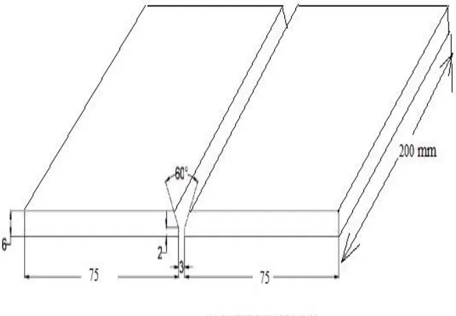
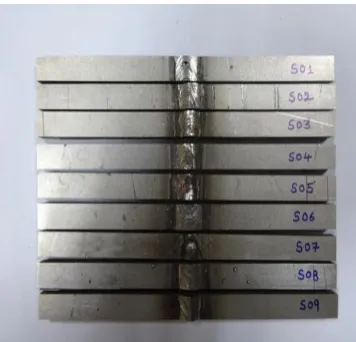
[image:3.612.135.467.454.684.2]he Shielded Metal Arc Welding (SMAW) was used for welding of 2205 duplex stainless steel (DSS) plates of 200 mm x 75 mm x 6 mm dimensions. The welding process parameters, which could influence the mechanical properties, were selected to be weld current (A), weld time (T), Electrode Material (F) and position of welding (Z). The materials for filler rods were 316 L, 308L and 310 L . The chemical composition of the base metal and filler rods are given in table 1. The weld joint design is shown in figure 1. The experiments were conducted using arc gap 2 mm, V-groove angle of 60o, root gap of 3 mm. The direct current electrode negative DCEN (Straight polarity) was employed during SMA Welding process.
TABLE I
BASE MATERIAL AND FILLER MATERIAL COMPOSITION
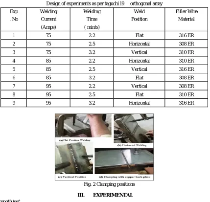
The Taguchi optimization method was selected to maximize the mechanical properties of welded bead. The four variable parameter Welding Current (A), Welding Time(T), Welding Position(Z), Filler Material(F) and their three levels were selected, the SMAW process parameter are given in the Table 2. The two plates were held as per the design using C-Clamping fixtures for the flat, horizontal and vertical position of welding with 3 mm root gap between the welding plates as shown in figure 2. A grooved copper back up plate having dimensions 2mm x 5mm was fixed below the welding plates to avoid the flow-off of weld metal from the weld joint. The electrode diameter used was 3 mm for all experiments. Two and half electrode was consumed for each 150 mm weld length.
Table ii
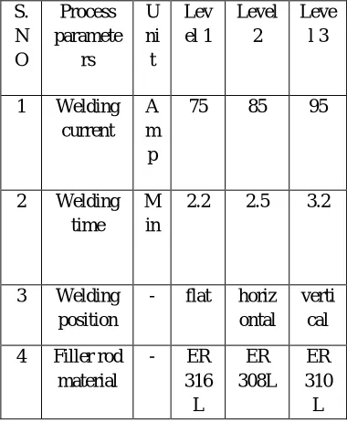
Sma welding process parameter and three levels S. N O Process paramete rs U ni t Lev el 1 Level 2 Leve l 3
1 Welding current
A m p
75 85 95
2 Welding time
M in
2.2 2.5 3.2
3 Welding position
- flat horiz ontal
verti cal
4 Filler rod material
- ER 316 L ER 308L ER 310 L
After conducting nine welding processes as per DOE, the experiments were carried out to measure the tensile strength, hardness, toughness by using UTM, Vickers hardness test and universal pendulum impact testing machine respectively in a bead on welded plates.
Components Base material composition 2205 DSS (base) Filler material ER 316L Filler material ER 308L Filler material ER 310L
C 0.024 0.03 0.03 0.08
Cr 22.821 18.5 21.5 25.5
Si 0.457 0.45 0.47 0.49
Mn 1.72 1.75 1.75 1.75
P 0.019 0.03 0.03 0.03
S 0.017 0.03 0.03 0.03
Mo 3.22 2.8 0.75 0.75
Ni 5.75 11.5 9.5 20.5
Fe Rem Rem Rem Rem
[image:4.612.211.401.446.677.2]Table iii
Design of experiments as per taguchi l9 orthogonal array
Exp Welding Welding Weld Filler Wire
. No Current Time Position Material
(Amps) ( mints)
1 75 2.2 Flat 316 ER
2 75 2.5 Horizontal 308 ER
3 75 3.2 Vertical 310 ER
4 85 2.2 Horizontal 310 ER
5 85 2.5 Vertical 316 ER
6 85 3.2 Flat 308 ER
7 95 2.2 Vertical 308 ER
8 95 2.5 Flat 310 ER
9 95 3.2 Horizontal 316 ER
Fig. 2 Clamping positions
III. EXPERIMENTAL A. Tensile strength test
This test is used to measure the tensile strength of a welded joint. The tensile strength, which is defined as stress in kgf per square meter. It is calculated by dividing the breaking load of the test piece by the original cross section area of the specimen. This test is used to measure the strength of a welded joint. A portion of the welded plate is locating the weld midway between the jaws of the testing machine, and then the load is applied gradually on the specimen until the specimen breaks. Then the breaking load is recorded. The width, thickness of the test specimen are measured before testing, and the area in square inches is calculated by multiplying width and thickness before testing , the area in square inches is calculated
.
[image:5.612.185.431.592.719.2]Fig. 4Tensile test specimens trail2
B. Vickers Hardness Test
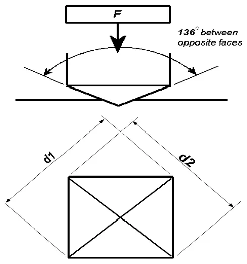
The Vickers hardness test is conducted by indenting the test material with a diamond indenter which is in the form of a right pyramid with a square base and an angle of 136 degrees between opposite faces subjected to a load of 50 kgf. The full load is applied perpendicularly to the surface for 15 seconds. The two diagonals of the indentation left in the surface of the material after removal of the load are measured using a microscope and their average is calculated. The area of the sloping surface of the indentation is calculated. The Vickers hardness is obtained by dividing the kgf load by the area of indentation.
d = Arithmetic mean of the two diagonals, d1 and d2in mm; HV = Vickers hardness; F= load in kgf.
Fig. 5 Vickers hardness formule
[image:6.612.186.431.457.718.2]Fig. 7 Hardness specimens
C. Impact Test
The two kinds of specimens used for impact testing are known as Charpy and Izod. Both test pieces are broken in an impact testing machine. The only difference is in the manner that they are anchored. The Charpy piece is supported horizontally between two anvils and the pendulum strikes opposite the notch. The Izod piece is supported as a vertical cantilever beam and is struck on the free end projecting over the holding vise.
Charpy test measures the welds ability to withstand an Impact force. Low Charpy test readings indicate brittle weld metal Higher
Charpy readings indicate the samples toughness. The toughness values of the weld-pieces are tabulated above. Weld-pieces are placed at the impact testing machine as simply supported. The hammer of the heavy weight is then released and corresponding
[image:7.612.220.393.360.522.2]values of weight provides the toughness values for weld-pieces
Fig. 8 Impact testing machine
[image:7.612.215.393.550.721.2]IV. EXPERIMENTAL RESULTS
Table iv
Experimental data of l9 taguchi orthogonal array, process parameters and corresponding response parameters values
Exp.No. Process parameters Response parameters
welding current
(amp)
welding time(min)
welding position
filler wire material
ultimate tensile strength
vickers hardness
impact energy
1 75 2.2 Flat 316ER 764.547 245.83 33
2 75 2.5 Horizontal 308ER 730.603 263.137 38
3 75 3.2 Vertical 310ER 502.69 265.93 32
4 85 2.2 Horizontal 310ER 700.931 253.51 33
5 85 2.5 Vertical 316ER 682.07 261.69 29
6 85 3.2 Flat 308ER 775.116 249.56 32
7 95 2.2 Vertical 308ER 576.363 245.737 30
8 95 2.5 Flat 310ER 737.777 243.373 47
9 95 3.2 Horizontal 316ER 518.788 251.037 30
V. TAGUCHIANALYSIS
TABLEV.DESIGNSUMMARY
Taguchi
Array L9(3^4)
Factors: 4
Runs: 9
A. Ultimate tensile strength versus welding current, welding time, welding position and filler wire material
TABLE VI
RESPONSE TABLE FOR SIGNAL TO NOISE RATIOS ULTIMATE TENSILE STRESS
Level
Welding Welding Welding filler current
(amp)
time(min) Position wire
Material
1 56.32 56.6 57.6 56.21 2 57.13 57.1 56.16 56.76 3 55.62 55.37 55.31 56.1 Delta 1.5 1.73 2.3 0.66
[image:8.612.81.527.115.514.2]95 85 75 57.5 57.0 56.5 56.0 55.5 55.0 3.2 2.5 2.2 VER TICA L HO RIZO NTA L
FLAT 310E
R 308E R 316E R A M e a n o f S N r a ti o s
B C D
Main Effects Plot for SN ratios
Data Means
[image:9.612.114.499.79.260.2]Signal-to-noise: Larger is better
Fig. 8 Ultimate tensile stress
It is observed that from table 6 the order of effect of input process parameters are welding position , welding time, welding current , and filler material. From Fig.8 the ultimate tensile stress is maximum when input parameters are welding current 85amps , welding time 2:50 minutes , flat position and filler material is 308ER.
[image:9.612.99.509.361.712.2]B. Vickers hardness versus welding current, welding time, welding position and filler wire material
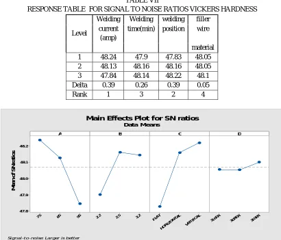
TABLE VII
RESPONSE TABLE FOR SIGNAL TO NOISE RATIOS VICKERS HARDNESS
Level
Welding Welding welding filler current
(amp)
time(min) position wire
material 1 48.24 47.9 47.83 48.05 2 48.13 48.16 48.16 48.05 3 47.84 48.14 48.22 48.1 Delta 0.39 0.26 0.39 0.05
Rank 1 3 2 4
95 85 75 48.2 48.1 48.0 47.9 47.8 3.2 2.5 2.2 VER TICA L HO RIZ ON TAL FLA T 310E R 308E R 316E R A M e a n o f S N r a ti o s
B C D
Main Effects Plot for SN ratios
Data Means
Signal-to-noise: Larger is better
It is observed that from table 7 the order of effect of input process parameters are welding current, welding position, welding time and filler material. From Fig.9 the hardness is maximum when input parameters are welding current 75amps , welding time 2:50 minutes , vertical position and filler material is 310ER
[image:10.612.131.479.162.523.2]C. Impact energy versus welding current, welding time, welding position and filler wire material
TABLE VIII
RESPONSE TABLE FOR SIGNAL TO NOISE RATIOS FOR : IMPACT ENERGY
Level
Welding Welding welding filler current
(amp)
time(min) position wire
material
1 30.69 30.09 31.31 29.72 2 29.91 31.43 30.5 30.41 3 30.84 29.92 29.63 31.31 Delta 0.94 1.51 1.67 1.58
Rank 4 3 1 2
95 85 75 31.5 31.0 30.5 30.0 29.5 3.2 2.5 2.2 VER TICA L HO RIZO NTA L
FLAT 310E
R 308E R 316E R A M ea n o f S N r a ti o s
B C D
Main Effects Plot for SN ratios
Data Means
Signal-to-noise: Larger is better
Fig. 10 Impact energy
It is observed that from table 8 the order of effect of input process parameters are welding position, filler material, welding time and welding current. From Fig.10 the impact strength is maximum when input parameters are welding current 95amps , welding time 2:50 minutes , flat position and filler material is 310ER
VI. CONCLUSION A. Ultimate tensile strength
The influence of filler wire material is minimum and welding position is maximum,. The maximum ultimate tensile strength is occurring for, when input parameters are welding current 85amps , welding time 2:50 minutes , flat position and filler material is 308ER.
B. Hardness
C. Toughness
The influence of welding current on the impact energy is minimum and welding position is maximum. From the result it was also observed that the maximum impact energy is occurring for, when input parameters are welding current 95amps , welding time 2:50 minutes , flat position and filler material is 310ER.
REFERENCES
[1] Pawan Kumar, Dr. B. K. Roy and Nishant ,“Parameters Optimization for Gas Metal Arc Welding of Austenitic Stainless Steel (AISI 304) & Low Carbon Steel using Taguchi’s Technique”, International Journal of Engineering and Management Research, Volume-3, Issue-4 ,August-2013.
[2] K.Kishore, P.V.Gopal Krishna, K.Veladri, G.Kiran Kumar, “Analysis of defects in Gas Shielded Arc welding of AA6351 using Taguchi methods” ,International Journal of Applied Engineering Research, Volume-5, 2010.
[3] A.Balaram Naik, A.Chennakesava Reddy, “An Experimental investigation of shielded metal arc welding process on duplex stainless steel to control and correction of distortion in welding”, International journal of engineering research ,volume-5 , February 2016.
[4] P. Sathiya, S. Aravindan, R. Soundararajan, “Effect of shielding gases on mechanical and metallurgical properties of duplex stainless-steel welds”, Journal of Materials Science, Volume-44, issue-1, January 2009.
[5] J. E. Ramirez and M. Johnson, “Effect of Welding Parameters and Electrode Condition on Alloying Enrichment of Weld Metal Deposited with Coated Cellulosic Electrodes”, Welding Journal, Volume-89, November 2010.
[6] Omar Bataineh, Anas Al-Shoubaki, Omar Barqawi
“Optimising Process Conditions in MIG Welding of Aluminum Alloys through Factorial Design Experiments” , Latest Trends in Environmental and Manufacturing Engineering, December 2012.
[7] N.D. Pandey,A Bharti and S R Gupta, “Study on effect of submerged Arc welding parameters and fluxes on element transfer behavior and weld metal chemistry”, Journal of Materials Processing Technology,Volume-42, 1994.
[8] Amit Pal, Sachin Handuja, “The Analysis of MIG Welding Parameters for Multi-Response optimization Using Taguchi’s Orthogonal Array and gray Relational
Approach” , International Journal of Advance Research in Engineering Science and Technology (IJAREST), 2014.
[9] Erdal Karadeniz, Ugur Ozsarac and Ceyhan Yildiz, “The Effect of Process Parameters on Penetration in Gas Metal Arc Welding Processes,” Material and Design, 2007.