International Journal of Emerging Technology and Advanced Engineering
Website: www.ijetae.com (ISSN 2250-2459,ISO 9001:2008 Certified Journal, Volume 3, Issue 12, December 2013)
Modeling, Analysis and Simulation for Voltage Regulation of a
Weak Bus System Using STATCOM
P. C. Pradhan
1, P. K. Ray
2, R. K. Sahu
3,
J. K. Moharana
4 1Faculty and Research Scholar, Dept. of EE, DRIEMS, Cuttack,
2 Dept.of EEE, IIIT, BBSR, 3Dept.of EE, VSSUT, Burla 4Dept.of EEE, GITA, BBSR
Abstract-- The interconnected grids tend to become unstable as the heavy loads vary dynamically in their magnitude and phase angle and hence power factor. Commissioning new transmission systems are extremely expensive and take considerable amount of time to build up. Voltage regulation of a weak bus is a challenging problem, particularly when it may not be economic to simply upgrade the network. The STATCOMs offer an attractive alternative, with their potential to provide both steady state and transient voltage compensation for a limited capital investment. However, operation of these systems with weak networks needs careful attention to achieve a stable and fast response under all supply conditions. This paper proposes a control strategy to regulate and balance the voltage at a weak bus using a STATCOM which, compared to other reported strategies, is more robust and works well under all system conditions. Simulation results are presented to verify the stability of this control strategy across a range of operating conditions. The operation of the STATCOM with supply system makes the rural consumers healthy and wealthy.
Keywords-- Controller design, PI Controller, STATCOM I. INTRODUCTION
In recent years power systems have become very complex with interconnected long distance transmission lines. The interconnected grids tend to become unstable as the heavy loads vary dynamically in their magnitude and phase angle and hence power factor. Commissioning new transmission systems are extremely expensive and take considerable amount of time to build up. Therefore, in order to meet increasing power demands, utilities must rely on power export/import arrangements through the existing transmission systems. In specially, the distribution networks supplying rural consumers are often quite weak because of the long distances involved and the relatively high R/X ratio of the cables that are used. Hence, as demand increases on these networks, power quality issues such as poor voltage regulation, voltage unbalance, low power factor and harmonics often become a significant problem.
Fig.1: Interconnected Six Bus system
The 6-bus system is a simple power system network given in Fig.1 and scaled model of a bus is shown in Fig.2.The 6-bus system is intended to illustrate in a simple context notions of transfer capability and the impact that various actions have on the given transfer capability. Buses 1, 2, 3 of the system diagram are generators and buses 4, 5, 6 of the diagram are loads. The primary flow of power is from the top of the diagram to the bottom of the diagram and also from left to right. Reactive demand by the loads (signified by the empty portion of the load arrows) is large. The network has 10 branches and each branch represents a transmission line. The model is an AC power flow model; it represents real and reactive power flows and power system nonlinearity. Operational limits relating to transmission line flow, voltage magnitude, and voltage collapse are represented. The weak bus no 5 is connected to industrial area and also local consumers. The voltage of this grid (Bus no.5) is very less than nominal value and hence its voltage can be regulated otherwise system will be collapsed.
International Journal of Emerging Technology and Advanced Engineering
Website: www.ijetae.com (ISSN 2250-2459,ISO 9001:2008 Certified Journal, Volume 3, Issue 12, December 2013)
564 Power electronic devices are gaining popularity for applications in the field of power transmission and distribution systems. The reactive power (VAR) compensation and control have been recognized [1] as an efficient & economic means of increasing power system transmission capability and stability.
The use FACTS (Flexible AC Transmission System) devices in a power system can potentially overcome limitations of the present mechanically controlled transmission systems. By facilitating bulk power transfers, these interconnected networks help minimize the need to enlarge power plants and enable neighboring utilities and regions to exchange power. The stature of FACTS devices within the bulk power system will continually increase as the industry moves toward a more competitive posture in which power is bought and sold as a commodity. As power wheeling becomes increasingly prevalent, power electronic devices will be utilized more frequently to insure system reliability and stability and to increase maximum power transmission along various transmission corridors. The FACTS device, such as STATCOM has been introduced more recently which employs a VSI with a fixed DC link capacitor as a static replacement of the synchronous condenser. In a traditional synchronous condenser, the field current of the synchronous motor controls the amount of VAR absorbed/injected and hence in a similar way, the firing instant of the 3-phase inverter controls the VAR flow into or out of the STATCOM. Large numbers of capacitor banks or inductor banks are no more required. Only a fixed set of capacitor provides the required VAR control, with a rapid control of bus voltage and improvement of utility power factor. It offers several advantages over conventional thyristorised converters [2] in terms of speed of response. The STATCOM is a voltage source inverter (VSI) based device, which regulates distribution bus voltage using reactive power compensation. The potential of STATCOM to improve supply quality and increase line utilization in weak distribution networks is well documented [3, 4]. However, many of the proposed control strategies assume a stiff, balanced grid source, and this is often not the case in practice. Recently, there has been some research focus on the performance of STATCOM devices operating under unbalanced supply conditions. Direct voltage control algorithms used to compensate for supply unbalance in distribution networks were proposed in [5] and [6]. However, the results in [6] show a relatively slow dynamic response because of the filters employed. Also, both algorithms have been developed for a VSI device interfaced to the distribution network through a simple inductive filter, and have not been tested for the more complex LCL filter considered in this work.
A multi-variable control strategy was proposed in [7] for a STATCOM with a LCL filter interface. Although this strategy is shown to achieve good steady state and dynamic responses under balanced and unbalanced supply conditions, it is complex and sensitive to variations in system parameters. The penalty paid for this improvement is in terms of introduction of some harmonics, which requires separate handling using active filtration techniques. Moran et al [8] have shown in details how the utilization of Sinusoidal Pulse Width Modulation (SPWM) techniques reduces harmonic distortion. It has also been shown that an increase of modulation index reduces the size of the link reactor and stress on switches which are significant issues in practical implementation. The modeling and analysis of STATCOM steady state and dynamic performance with conventional control method have been studied by Schauder and Mehta [9] using non-linear controller. In [10, 11] the dynamic responses and steady state behavior of STATCOM with Space Vector Pulse Width Modulation (SVPWM) has been studied and the advantages of introducing SVPWM inverter with higher values of modulation index are highlighted.
The controllable reactive power allows for a rapid control of bus voltage and power factor at the system or at the load end. To compensate for the distorted current drawn by the rectifiers from the utility grid, the STATCOM and its current controller must have the capability to track source PWM (Pulse Width Modulation) converters. The linear control is more suitable for STATCOM application reported in [13, 14]. The present paper suggests the design of a linear current controller and voltage controller on the basis of gain and time constant adjustment along with the parameter of the coupling inductor and storage capacitor. The system modeling using STATCOM is shown in Fig.4.
International Journal of Emerging Technology and Advanced Engineering
Website: www.ijetae.com (ISSN 2250-2459,ISO 9001:2008 Certified Journal, Volume 3, Issue 12, December 2013)
The present paper goes on to develop closed loop model for investigating transient performance of the STATCOM by using controller parameter. First, in Section 2 focuses on state space model of the STATCOM with the system. Secondly, in Section 3, a current and voltage controllers are designed. The simulated responses with the designed controller parameters are presented in Section 4. This scheme is both an extension and a significant improvement of the scheme suggested by Shauder et al [9] and Sensarma et al [4].The results obtained have been compared and appropriate conclusions have been drawn.
II.MODELING OF THE STATCOM AND ANALYSIS
A. Operating Principle
As is well known, the STATCOM is, in principle, a static (power electronic) replacement of the age-old synchronous condenser. Fig.4 shows the schematic diagram of the STATCOM at PCC through coupling inductors. The fundamental phasor diagram of the STATCOM terminal voltage with the voltage at PCC for an inductive load in operation, neglecting the harmonic content in the STATCOM terminal voltage, is shown in Fig.5. Ideally, increasing the amplitude of the STATCOM
terminal voltage
V
oa above the amplitude of the utility voltageV
sa causes leading (capacitive) currentI
ca to be injected into the system at PCC as shown in Fig.5.B. Modeling
The modeling of the STATCOM, though well known, is reviewed in the lines below, for the sake of convenience. The modeling is carried out with the following assumptions:
1) All switches are ideal
2) The source voltages are balanced
3)
R
srepresents the converter losses and the losses of the coupling inductorFig.4: Schematic diagram of STATCOM
Fig.5: Phasor diagram for inductive load operation 4) The harmonic contents caused by switching action
are negligible
The 3-phase stationary
abc
coordinate vectors with 1200 apart from each other are converted into
2-phase stationary coordinates (which are in quadrature). The
axis is aligned witha
axis and leading
axis and both converted intodq
two-phase rotating coordinates. The Park’sabc
todq
transformation matrix is
2
/
1
2
/
1
2
/
1
)
3
/
2
(
)
3
/
2
(
)
(
)
3
/
2
(
)
3
/
2
(
)
(
3
2
t
Sin
t
Sin
t
Sin
t
Cos
t
Cos
t
Cos
K
(1)The actual proposed circuit is too complex to analyze as a whole, so that it is partitioned into several basic sub-circuits, as shown in Fig.4. The 3-phase system voltage
abc s
v
, lagging with the phase angle
to the STATCOM output voltagev
o,abc and differential form of the STATCOM currents are defined in (2) and (3).
3 2 (
) 3 2 (
) ( 3
2 ,
t Sin
t Sin
t Sin
s V
sc v
sb v
sa v
abc s v
(2)
icabc Rsicabc vsabc vo abc dtd s
L , , , ,. (3)
Where ,
V
s,
,
R
sandL
s have their usual connotations. The above voltages and currents are transformed intodq
frames
i
cqR
si
cqwL
si
cdv
sqv
oqdt
d
International Journal of Emerging Technology and Advanced Engineering
Website: www.ijetae.com (ISSN 2250-2459,ISO 9001:2008 Certified Journal, Volume 3, Issue 12, December 2013)
566 s
i
cdwL
si
cqR
si
cdv
sdv
oddt
d
L
(4b) The switching function S of the STATCOM can be defined as follows ) 3 2 ( ) 3 2 ( ) ( 3 2 wt S in wt S in wt S in m c S b S a S
S (5)
The modulation index, being constant for a programmed PWM, is given by,
m dc V peak o v MI 3 2 ,
(6)
The STATCOM output voltages in
dq
transformation arevo,qdom
0 1 0
Tvdc (7) The DC side current in the capacitor indq
transformation
ico Tcd i cq i m dc i
0 1 0 (8)
The voltage and current related in the dc side is given by
dc
i
cdC
m
dt
dv
(9)The complete mathematical model of the STATCOM in
dq
frame is obtained as given in (10) 0 0 0 0 Cos Sin L V v i i C m L m L R w w L R v i i dt d s s dc cd cq s s s s s dc cd
cq (10)
C. Steady State and Transient Analysis
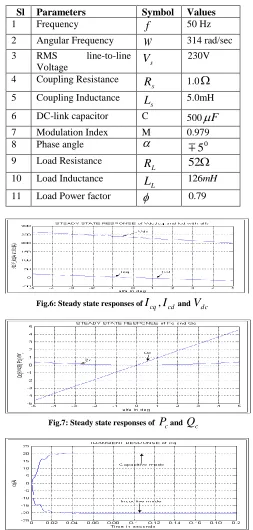
[image:4.612.320.573.154.684.2]The detailed steady state and transient responses with the Table.I are given in Fig.6-9 and responses suggest the static and dynamic conditions of the STATCOM. It can be seen that the transient responses take about one and half power cycle to reach at their steady state values.
Table I
It Shows The System Parameters
Sl Parameters Symbol Values
1 Frequency
f
50 Hz2 Angular Frequency
w
314 rad/sec3 RMS line-to-line
Voltage
V
s230V
4 Coupling Resistance s
R
1.0
5 Coupling Inductance s
L
5.0mH6 DC-link capacitor C 500
F
7 Modulation Index M 0.9798 Phase angle
05
9 Load Resistance
L
R
52
10 Load Inductance
L
L
126mH11 Load Power factor
0.79Fig.6: Steady state responses of
I
cq,I
cdandV
dcFig.7: Steady state responses of
P
candQ
c [image:4.612.51.284.565.642.2]International Journal of Emerging Technology and Advanced Engineering
Website: www.ijetae.com (ISSN 2250-2459,ISO 9001:2008 Certified Journal, Volume 3, Issue 12, December 2013)
Fig.9: Transient responses of
v
dc in capacitive and inductive III. DESIGN OF CONTROLLERSWith the assumption of the system voltage and STATCOM output voltage are in phase and hence the equation (10) can be modified as given in equation (11)
od
v
oq
v
sd
v
sq
v
s
L
cd
i
cq
i
s
L
s
R
s
L
s
R
cd
i
cq
i
dt
d
1
(11)So the equation (11) is a Multiple Input and Multiple Output (MIMO) system and its input and output are given as
cd cq od oqi
i
y
v
v
u
,
(12)The block diagram of the STATCOM in d-q transformation as per (11) is shown in Fig.10.The instantaneous voltage of the system and the STATCOM are independent, but the active and the reactive currents are coupled with each other through the reactance of the coupled inductor. So it is very essential to decouple the active and reactive current from each other and design the controller for tracking the required value.
Fig.10: Equivalent Diagram on a.c.side of STATCOM
A. Design of Current Controller
The current controller design for the above system can be done using the strategy [8-9] attempts to decouple the d and q axes equations, so that the MIMO system reduces to two independent Single Input Single Output (SISO) system. Hence, the control inputs
od
v and voq are configured as sd v cd i s wL od v od v sq v cq i s wL oq v oq v * * (13)
The equation (14) can be obtained by replacing (11) by (13). Hence each row of (14) is independent of each other and thus defines an independent SISO system. Conventional frequency-domain design methods can now be directly applied for current controller. Taking the Laplace transformation of both sides of (14) and rearranging terms are given by (15) and their decoupled SISO system is shown in Fig.11.
* * 1 0 0 od v oq v s L cd i cq i s L s R s L s R cd i cq i (14) s sL s R s od V s d I s d G s sL s R s oq V s q I s q G 1 ) ( * ) ( ) ( , 1 ) ( * ) ( )( (15)
Fig.11: Current control of inverter of equivalent decoupled SISO systems
For similar dynamic behaviour of the
d
andq
- axis currents, both thed
andq
- axis controllers are identical and its transfer function is given in (16)s sL s R s od V s cd I s oq V s cq I s i G 1 ) ( * ) ( ) ( * ) ( )
International Journal of Emerging Technology and Advanced Engineering
Website: www.ijetae.com (ISSN 2250-2459,ISO 9001:2008 Certified Journal, Volume 3, Issue 12, December 2013)
568 The transfer function of a PI controller is
s i K p K i s K s pi
G
1 1 )
( (17)
With
i K i K K p K
, . The transfer function in open
loop of PI controller associated with the transfer function on the a.c. system is
s R s L s
s R
i s K s i G s pi G
1 1 1
1 ) ( ). (
(18)
While taking
s R
s L i
and on simplification reduces to
s sL
K s i G s pi
G ( ). ( ) (19)
The closed loop transfer function is
K s L s T
1 1
(20)
Thus the system behaves like a first order with an apparent time constant as
K
L
si
(21)The gain of K can be adjusted such a way that if it is increased too high then the system behaves as second order, otherwise responses very slow. Hence the numerical values for KpandKiare decided from the
circuit parametersLsandRs from the required value of K. So the parameters of PI controller are defined as
s L
s KR i K K p
K , (22)
Where,
p s i
K
L
which is taken as 0.3mseconds andwith the parameters given in Table-1, value of
9
.
16
piK
andK
ii
3
.
3
10
3 are calculated. These parameters are used ind
andq
- axis current controller. The structure of the effective closed loop system is shown in Fig.12 and is replicated in both thed
andq
- axis current controllers. Bode plot of the system with controller is shown in Fig.13, which is a first order system.Fig.12: Effective closed loop current control system
B. Design of Voltage Controller
The relation between dc voltage dc
v and dc current
i
dcis
idcdt C dc
v 1 (23)
The transfer function can be written as
sC dc I
dc V s v
G ( ) 1 (24)
Fig.13: Bode plot of the system with PI controller Neglecting the power loss in the source resistance and power losses in the switches, balancing the power on both sides,
International Journal of Emerging Technology and Advanced Engineering
Website: www.ijetae.com (ISSN 2250-2459,ISO 9001:2008 Certified Journal, Volume 3, Issue 12, December 2013)
From the above equation, we have
0
.
46
500
230
dc s dc sd cd dc
V
V
v
v
i
i
(26)
With
V
dc as the reference, the voltage control loop is shown in Fig.14 and it consists of innerd
- axis current control loop. The active power is supplied by thed
-axis current which is nothing but the ripple current of the capacitor. To make the steady state error of the voltage loop zero Proportional control is adopted here and it produces the referenced
-axis current for the control of thed
-axis current. The design of voltage controller is as follows:The open loop transfer function of DC bus voltage controller is
sC
K
K
G
op dc*
(27)The closed loop transfer function with unity feed back gain is
dc cl
K
K
sC
G
*
1
1
(28)Where ,
dc v
K
K
C
*
and taking
v
1msecond andwith the parameters of Table. I, the value of
K
dc
1
.
08
Fig.14: DC link voltage control loop
Then Proportional Integral controller is considering for the voltage control. Hence, the transfer function of PI controller in (17) is associated with the transfer function on dc side is
sC v s K ol s pi G s v
G ( ). ( ) 1 1 1
(29)
After taking
v
C
and on simplification
1
2 2)
(
).
(
v v ol
pi v
s
s
K
s
G
s
G
(30)
The transfer function in closed loop
K
s
s
s
s
G
s
G
v v
v cl
pi
v 2 2
1
1
)
(
).
(
(31)
So the system behaves like a second order system. As
K
v v
2
and magnitude plot in Fig.10 shows the initial slop at break point is approximately –20db/decade and hence it reduces to first order system. The value of K can be determined form root locus with approximate settling time as given in (32) and implementation block diagram is shown in Fig.15. 0.15, 200 C K vi K K
pv
K (32)
(a)
(b)
International Journal of Emerging Technology and Advanced Engineering
Website: www.ijetae.com (ISSN 2250-2459,ISO 9001:2008 Certified Journal, Volume 3, Issue 12, December 2013)
570 IV. SIMULATION RESULTS
The transient performances of the control strategy under balanced and unbalanced supply conditions have been studied using the STATCOM model,Fig.16(a) shows that without compensation, the voltage increases by approximately 6% from 167 V to 174 V when the load reduces. Fig.16 (b) shows the compensated simulated waveform with STATCOM. Due to unbalanced supply, simulated waveforms are given in Fig.17. Fig.18 shows the system response and injected current when the STATCOM is connected to the supply system. It can be seen that the device responds within one cycle of the switch. As expected, the voltage before and after the disturbance is maintained at 1p.u.
(a)
(b)
Fig.16: Results in balanced supply: (a) Simulation voltage without STATCOM, (b) Simulation voltage with STACOM
Fig.17: Results due to unbalanced supply
Fig.18: Injection of STATCOM current V. CONCLUSION
This paper has described a synchronous reference control, strategy to regulate and balance the voltage at a weak bus in six bus system using a STATCOM device. This control strategy was developed specifically for a PWM controlled voltage source inverter connected to the weak bus network through a.c filter. Simulation results have demonstrated that the controller achieves balanced voltages at the weak bus while maintaining a fast transient response. It has also been shown that the interaction between a STATCOM device and a weak bus network is sensitive to non-ideal supply conditions and load variation. Therefore, tuning of the controller to achieve a fast and stable response under varying system conditions requires careful design and investigation for each specific installation. It has also been shown that the interaction between a STATCOM device and a supply system makes the rural consumers healthy and wealthy.
REFERENCES
[1] A.T. Johns, A.Ter-Gazarian and D.F.Wame,”Flexible ac transmission systems (FACTS)”, IEE Power and Energy Series, London, U.K.
[2] R.M.Mathur and R.K. Varma, “Thyristors-based FACTS Controllers for Electrical Transmission Systems, IEEE Press”, Wiley-Interscience Publication.
[3] Z. Saad-Saoud, M. L. Li:jboa, J. B.Ekanayake, N. Jenkins, and G. Strbac, "Application of STATCOMs to wind farms," IEE
Proceedings. Generation, Transmission & Distribution, vol. 145, pp. 51 1-518, 1998
[4] P. S. Sensarma, K. R. Pa.diayar and V. Ramanarayanan, "Analysis and Performance Evaluation of a Distribution STATCOM for Compensating Voltage Fluctuations," IEEE Transactions on Power Delivery, vol 16.no. 2, April 200 I .
[5] C. Hochgrnf and R. H. Lasseter, "Statcom controls for Operation with Unbalanced Voltages", IEEE Transactions on Power Delivery.
vol. 13,no. 2, April 1998.
[6] S.Chen, G. Joos and L. T. Moran, "Dynamic Performance of PWM STATCOMs Operating under Unbalance and Fault Conditions in Distribution Systems", in Proc. of IEEE Power Engineering Socieg
Wififter M eeting, 2001, vol. 2, pp. 950-955.
[7] G. Ledwich and A. Ghosh, "A flexible DSTATCOM operating in voltage or current control mode", IEE Proc.-Gener. Trunsm.Distrbi.,
vol. 149, no. 2, March 2002.
International Journal of Emerging Technology and Advanced Engineering
Website: www.ijetae.com (ISSN 2250-2459,ISO 9001:2008 Certified Journal, Volume 3, Issue 12, December 2013) [9] C. Shauder and H. Mehta, “Vector analysis and control of advanced
static VAR compensators”, IEE Proc, 140, No. 4, July 1993. [10] A. Draou, M. Benghanem and A. Tahiri, “Multilevel Converter and
VAR Compensation”, Power Electronics Handbook”, pp.599-611, Academic Press, 2001.
[11] M.Sengupta,J.K Moharana and A.Sengupta,“ Study on an Advanced Static VAR Compensator switched from a Space Vector PWM inverter –Analysis, simulation and comparison with the conventional sinusoidal PWM, NPEC 2003, IIT Bombay,16-17 Oct 03 pp 72-78. [12] D.M.Brod and D.W.Novotny, “Current control of VSI- PWM
inverter ”IEEE Trans. Industrial Appl, Vol.IA-21, pp.562-570, July/Aug. 1985.
[13] S.Buso, L.Malesani and P.Mattavelli, “Comparison of Current Control Techniques for Active Filter Application ”IEEE Trans. Industrial Electronics, Vol.45, No.5, pp.722-729, October 1998. [14] A.M. Kulkarni and K.R. Padiyara, “Design of Reactive Current and
Voltage Controllers of Static Condenser”, Power and Energy System, Vol.19, No.6, pp.397-410, 1997