International Journal of Emerging Technology and Advanced Engineering
Website: www.ijetae.com (ISSN 2250-2459,ISO 9001:2008 Certified Journal, Volume 5, Issue 11, November 2015)
309
MISO Type Mixed-Mode Biquad Filter Using Basic Active
Elements
Chen-Nong Lee
Department of Computer and Communication Engineering, Taipei City University of Science and Technology, Taipei, Taiwan, R. O. C.
Abstract— This paper presents a new
multiple-voltage/current-input single-voltage/current-output type (MISO type) mixed-mode (including voltage, current, transadmittance, and transimpedance modes) biquad filter using only two basic active elements (i.e. second-generation current conveyors (CCIIs)), two grounded capacitors and two resistors, which are the least number of basic active components and the minimum number of passive components necessary for realizing current-mode all five universal filtering responses (lowpass, highpass, bandpass, notch, and allpass), in addition to voltage-mode bandpass, lowpass, transadmittance-mode highpass, bandpass, and transimpedance-mode bandpass, lowpass filtering responses without changing the filter topology. This represents the attractive feature from chip area and power consumption point of view. Moreover, the proposed biquad filter still achieves many advantages like having no need of components matching conditions, in addition to the employment of two grounded capacitors (attractive for integration), no need of inverting-type input signals or double-type input signals for the use of special input signals, high output impedance for current output and low sensitivity performance. H-Spice simulation results confirm the theory.
Keywords—Active filters, basic active components, second-generation current conveyors, mixed-mode, biquad filter.
I. INTRODUCTION
Over the last decade, many voltage or current-mode universal biquad filters using different active elements have been reported. In some applications, however, we might intend to connect the voltage-mode circuits with the current-mode circuits. Thus, the transadmittance (i.e. input as voltage and output as current) and transimpedance (i.e. input as current and output as voltage) modes may play a very important role in the special filtering applications where we need to connect a voltage mode circuit with a current mode circuit and vice versa.
Therefore, the mixed-mode (input and output signals can be voltage or current) circuits are worthy of researches and presented for the use of any filtering requirement which is
compatible with modern microelectronic systems
applications, such as controls and voice and data communications, where consideration of size and weight make the use of inductors prohibitive.
In the past several decades, many mixed-mode filters using different active elements have been proposed [1-31]. The applications and advantages in the designing mixed-filters using basic active elements, such as second-generation current conveyors (CCIIs), have received considerable attentions [1, 2, 7, 10, 18, 20, 21, 26, 30, 31]. The CCII has simpler implementation configuration than the other current conveyors, such as, differential voltage current conveyor (DVCC), differential difference current conveyor (DDCC), fully differential current conveyor
(FDCCII), differential difference current conveyor
transconductance amplifier (DDCCTA), differential
voltage current conveyor transconductance amplifier
(DVCCTA), current controlled current conveyor
International Journal of Emerging Technology and Advanced Engineering
Website: www.ijetae.com (ISSN 2250-2459,ISO 9001:2008 Certified Journal, Volume 5, Issue 11, November 2015)
310
The biquad can realize all five universal filtering responses (lowpass, highpass, bandpass, notch, and allpass) from the voltage and current output terminals. However, it needs to use seven CCIIs, eight resistors, and two grounded capacitors. In [2], a mixed-mode universal biquad filter using CCIIs is proposed. However, it needs to use five CCIIs, seven resistors, and two grounded capacitors. Few mixed-mode (including voltage, current, transadmittance, and transimpedance modes) universal biquad filters which use only three CCIIs have been presented [7, 10]. For example, in [7], the mixed-mode biquad filter uses three CCIIs but it needs to use two switches and two/three grounded capacitors in addition to four resistors. In [10], the mixed-mode biquad filter also employs three CCIIs, four resistors, and two capacitors but it needs to use floating capacitors which are not attractive for monolithic IC implementation. In 2009, Lee and Chang proposed a single FDCCII-based mixed-mode biquad filter [13]. The biquad filter [13] is based on one active element, namely fully differential current conveyor (FDCCII), and five floating/grounded passive elements. However, the FDCCII is not a basic active element. It can be divided into two separate DDCCs whereas the internal structure of the DDCC is also complex. Therefore, a FDCCII has more complex implementation configuration than two CCIIs. In 2011, the reported mixed-mode universal biquad [24] use only three DDCCs, four resistors, and two grounded capacitors. However, the DDCCs are more complex active elements than the CCIIs. In 2013, the recent publication [27] reported that mixed-mode biquad uses only four multiple-output current controlled second-generation current conveyors (MOCCCIIs) and two grounded capacitors. However, the biquad, reported in [27], needs to use four
MOCCCIIs. In 2013, a new current-mode and
transresistance-mode (i.e. transimpedance-mode) universal biquad filter was proposed by Lee [26]. Although the biquad filter [26] uses only two multiple-output CCIIs (MOCCIIs) in addition to two grounded capacitors and three grounded resistors, it can not be operated in voltage-mode and transadmittance-voltage-mode. Moreover, the biquad filter [26] needs to use three resistors. In 2013, the recently reported mixed-mode [28] biquad using only two voltage differencing transconductance amplifiers (VDTAs) and two grounded capacitors can realize all five universal filtering functions, but the biquad in [28] has not included current-mode and transimpedance-current-mode.
In 2014, the very recently reported mixed-mode [29] biquads using three OTAs and two grounded capacitors can realize all five universal filtering functions, but the biquad filter in [29] needs to use three basic active elements. Moreover, the biquad filter [29] only can be operated in transadmittance-mode.
Therefore, this leads to prospective research work: investigating and developing a mixed-mode (including voltage, current, transadmittance, and transimpedance modes) biquad filter structure using the least number of basic active components and the minimum number of passive components. In this paper, the proposed multiple-voltage/current-input single-voltage/current-output type (MISO type) circuit using only two CCIIs (i.e. the least number of basic active components), two grounded capacitors and two resistors (i.e. the minimum number of passive components), which can be operated in all four possible modes (i.e. voltage, current, transadmittance, and transimpedance modes) and can realize current-mode all five universal filtering responses (lowpass, highpass, bandpass, notch, and allpass) in addition to voltage-mode
bandpass, lowpass, transadmittance-mode highpass,
bandpass, and transimpedance-mode bandpass, lowpass filtering responses without changing the filter topology. Moreover, the proposed circuit still achieves many important advantages which are (i) using commercially available active components, (ii) using only two grounded capacitors at the Z terminals of the CCIIs (attractive for monolithic IC implementation and absorbing shunt parasitic capacitance), (iii) high output impedance for current output, (iv) no need to impose component choice, (v) no need of inverting-type input signals or double-type input signals for the use of special input signals, and (vi) low active and passive sensitivities.
II. PROPOSED CIRCUIT
Figure 1 shows the proposed MISO type mixed-mode biquad filter structure using only two CCIIs, two grounded
capacitors and two resistors where Iin1, Iin2, and Iin3 are the
filter input currents and Vin1 and Vin2 are the filter input
voltages whose setting determine the filter functions as
shown later, Iout and Vout are the filter current output and
International Journal of Emerging Technology and Advanced Engineering
Website: www.ijetae.com (ISSN 2250-2459,ISO 9001:2008 Certified Journal, Volume 5, Issue 11, November 2015)
[image:3.612.55.282.138.351.2]311
Figure 1. Proposed MISO mixed-mode biquad filter structure.
Using standard notation, the port relations of a CCII can
be characterized by IY = 0, VX = VY and IZ± = ±IX. The
multiple current outputs of CCII(1) can be simply reconstructed using current mirrors. Moreover, the current output has very high output impedance. We notice that two grounded capacitors at the Z terminals of two CCIIs are attractive for integration and absorbing shunt parasitic capacitance. Routine circuit analysis for Figure 1 yields the following transfer functions:
) (
) ( )
( 1 2
1 s D
s N G s N
Iout (1)
and
) (
) ( )
( 4
3 s D
s N s N
Vout (2)
in which
3 2 1 2 1 1 1 2 1 2
1(s) s CC Iin sCGIin GG Iin
N (3)
2 2 1 1 2 1 2
2(s) s CCVin sCGVin
N (4)
3 1 2 2 1 1 2
3(s) sC Iin GIin (sC G)Iin
N (5)
2 2 1 1 1 2
4(s) sCGVin GGVin
N (6)
2 1 1 1 2 1 2 )
(s s CC sCG GG
D (7)
From equation (1)-(7), the mixed-mode biquad filter transfer functions are obtained according to input voltage or current conditions as follows.
Part I: If Vin1 = Vin2 = 0, the following current-mode all
five universal filtering responses can be obtained from Iout
as below.
(i) Highpass: Iin1 = Iin, and all the other input
currents are zero.
(ii) Lowpass: Iin3 = Iin, and all the other input
currents are zero.
(iii)Bandpass: Iin2 = Iin, and all the other input
currents are zero.
(iv)Notch: Iin1 = Iin3 = Iin, and the other input current
is zero.
(v) All-pass: Iin1 = Iin2 = Iin3 = Iin.
Part II: If Vin1 = Vin2 = 0, the following
transimpedance-mode bandpass and lowpass filtering responses can be
obtained from Vout as below.
(i) Bandpass: Iin1 = Iin, and all the other input
currents are zero.
(ii) Lowpass: Iin2 = Iin, and all the other input
currents are zero.
Part III: If Iin1 = Iin2 = Iin3 = 0, the following
voltage-mode bandpass and lowpass filtering responses can be
obtained from Vout as below.
(i) Bandpass: Vin1 = Vin, and the other input
voltage is zero.
(ii) Lowpass: Vin2 = Vin, and the other input voltage is
zero.
Part IV: If Iin1 = Iin2 = Iin3 = 0, the following
transadmittance-mode highpass and bandpass filtering
responses can be obtained from Iout as below.
(i) Highpass: Vin1 = Vin, and the other input
voltage is zero.
(ii) Bandpass: Vin2 = Vin, and the other input voltage
is zero.
Note that there are no critical component-matching conditions or cancellation constraints in the design. Moreover, the structure does not need inverting-type input current signals or double-type amplifier and also does not need to change the network topology.
Inspection of Eq. (7) shows that, in all cases the
parameters ω0, ω0/Q, and Q are given by
2 1
2 1 0
C C
G G
International Journal of Emerging Technology and Advanced Engineering
Website: www.ijetae.com (ISSN 2250-2459,ISO 9001:2008 Certified Journal, Volume 5, Issue 11, November 2015)
312
2 1 0 C G Q (9) 1 1 2 2 G C G CQ (10)
From Eqs. (8) and (9), the parameters ω0 and ω0/Q are
orthogonally adjustable through the resistor R1 and then the
resistor R2 in that order. From Eqs. (8) and (10), the
parameters ω0 and Q are interactive. However,
non-interactive filter parameter control can be obtained as
follows: for the fix-valued capacitors, ω0 can be tuned
arbitrarily without disturbing Q by simultaneously
changing G1 and G2 and keeping the ratio G2/G1 constant.
The parameter Q also can be adjusted without disturbing ω0
by simultaneously changing G2 and G1 and keeping the
product G2G1 constant.
III. NONIDEAL ANALYSIS
Taking the tracking errors of the CCII into account, the relationship of the terminal voltages and currents can be
written as: IY = 0, VX = β(s)VY, IZ± = ±α(s)IX, where α(s)
and β(s) represent the frequency transfer functions of the internal current and voltage followers of the CCII. They can be approximated by the first order lowpass functions [32, 33]. For frequencies much less than the corner frequencies of the CCII, all α(s) and β(s) are real quantities of magnitudes slightly less than one [32, 33]. Assuming the circuit works at frequencies much less than the corner
frequencies of α(s) and β(s), namely, α(s) = α = 1-εi and εi
(εi << 1) denotes the current tracking error of the CCII and
β(s) = β = 1-εv and εv (εv << 1) denotes the voltage
tracking error of the CCII. Taking into account the idealities of the CCII(1) and CCII(2), we obtain the non-idealities as below:
X Z X Z X Z Y X Y I I I I I I V V I 12 11 1 10 1 , , , , 0
for CCII(1) (11)
X Z
Y X
Y V V I I
I 0, 2 , 20 for CCII(2) (12)
The non-ideal denominator of the mixed-mode transfer functions becomes: 2 1 10 20 2 1 1 12 1 1 2 1 2 )
(s s CC sCG GG
D (13)
The ω0 and Q of the non-ideal mixed-mode biquad are:
2 1 2 1 1 2 10 20 0 C C G G
(14)
1 1 1 2 2 2 20 10 12 1 C G C G Q
(15)
The active and passive sensitivities of ω0 and Q are:
2
1
0 1 2 10 20 0 2 1 0 21, , , , ,
S
S
S
G G C C
2
1
1 2 20 10 1 1 22, , , ,
Q Q QG C Q
G
C
S
S
S
S
1
12
QS
,
00
1 2 1 1,
S
,
0
11
QS
(16)
From (16), the proposed MISO mixed-mode biquad filter has low active and passive sensitivities (not larger than unity in absolute value).
IV. H-SPICE SIMULATIONS
Two possible CMOS implementations of the CCII± are shown in Fig. 1 of Ref. [34] (without the cascode configuration) [35] and Fig. 2 (with the cascode configuration) [36]. Note that if the cascode configuration is not used in CCII, DVCC, DDCC, FDCCII, DDCCTA, DVCCTA, and CCCCTA, the CCII has simplest implementation configuration in all of them. Similarly, if the cascode configuration is used in CCII, DVCC, DDCC, FDCCII, DDCCTA, DVCCTA, and CCCCTA, the CCII also has simplest implementation configuration in all of them. Note that the multiple current outputs CCII applying the realization of current replicas are very simple. To verify the theoretical analysis of the proposed biquad filter, the H-SPICE simulations with the NMOS transistor aspect ratios (W/L=5μm/1μm) and PMOS transistor aspect ratios (W/L=10μm/1μm) of Fig. 2, using the TSMC 0.25μm process with the parameters of level 49 for the proposed MISO mixed-mode circuit of Fig. 1, were performed with
the component values: C1 = C2 = 8pF and G1 = G2 =
100.532824μS, for lowpass, bandpass, highpass, notch, and
allpass filters, leading to a center frequency of f0 = 2MHz
and quality factor of Q = 1. Their supply voltages are VDD =
-Vss = 1.25V, Vb1 = -0.3V, and Vb2 = -0.6V. Fig. 3
International Journal of Emerging Technology and Advanced Engineering
Website: www.ijetae.com (ISSN 2250-2459,ISO 9001:2008 Certified Journal, Volume 5, Issue 11, November 2015)
313
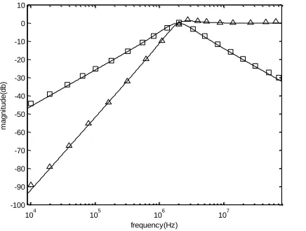
Fig. 6 presents the simulated transadmittance-mode bandpass and highpass amplitude-frequency responses of
the proposed biquad filter with the normalized
transadmittance magnitude = 20 log
|Iout/(0.000100532824Vin)| dB due to G4 = 100.532824μS.
[image:5.612.331.541.146.311.2]Although not included in this paper, it can be shown that the other modes simulated results are very similar to the above simulated results. As can be seen, there is a close agreement between theory and simulation.
Figure 2. CMOS implementation of the CCII± (with the cascode configuration).
105 106 107
-70 -60 -50 -40 -30 -20 -10 0 10
frequency(Hz)
m
a
g
n
it
u
d
e
(d
b
)
Figure 3. Current-mode bandpass and notch amplitude-frequency
responses of the proposed biquad filter (*, simulated bandpass; □,
simulated notch; and ____, theoretical curve ).
105 106 107
-90 -80 -70 -60 -50 -40 -30 -20 -10 0 10
frequency(Hz)
m
a
g
n
it
u
d
e
(d
b
[image:5.612.52.288.248.408.2])
Figure 4. Current-mode highpass and lowpass amplitude-frequency
responses of the proposed biquad filter (○, simulated highpass; □,
simulated lowpass; and ____,theoretical curve ).
104 105 106 107
-400 -350 -300 -250 -200 -150 -100 -50 0 50 100
frequency(Hz)
p
h
a
s
e
(d
e
g
re
e
)
m
a
g
n
it
u
d
e
(d
b
)
10 5 0 -5 -10 -15 -20 -25 -30 -35 -40
Figure 5. Current-mode allpass phase and amplitude frequency
responses of the proposed biquad filter (□, simulated phase; *,
[image:5.612.336.556.357.520.2]International Journal of Emerging Technology and Advanced Engineering
Website: www.ijetae.com (ISSN 2250-2459,ISO 9001:2008 Certified Journal, Volume 5, Issue 11, November 2015)
314
104 105 106 107
-100 -90 -80 -70 -60 -50 -40 -30 -20 -10 0 10
frequency(Hz)
m
a
g
n
it
u
d
e
(d
b
[image:6.612.62.280.145.310.2])
Figure 6. Transadmittance-mode highpass and bandpass amplitude-frequency responses with the normalized transadmittance magnitude
of the proposed biquad filter (Δ, simulated highpass; □, simulated
bandpass; and ____,theoretical curve ).
V. CONCLUSIONS
None of the previously reported mixed-mode (including voltage, current, transadmittance, and transimpedance modes) biquad filters can offer the following attractive advantage: using only two second-generation current conveyors (i.e. the least number of basic active components), two grounded capacitors, and two resistors (i.e. the minimum number of passive components). In this paper, the proposed MISO type mixed-mode (including voltage, current, transadmittance, and transimpedance modes) biquad filter can achieve the above attractive advantage. Moreover, the proposed MISO mixed-mode circuit still enjoys many main advantages: using commercially available active components, no component-value constraints, no inverting or non-inverting amplifiers for special input signals, using grounded capacitors attractive for integration and for absorbing shunt parasitic capacitance, high output impedance for current output, and low active and passive sensitivities. H-Spice simulations with TSMC 0.25μm process confirm the theoretical predictions.
Acknowledgements
The author would like to thank the Ministry of Science
and Technology of Taiwan, R. O. C. The Ministry of
Science and Technology, Taiwan, R. O. C. supported this work under grant number MOST 104-2221-E-149-001-.
REFERENCES
[1] M. T. Abuelma‘atti, A. Bentrcia, and S. M. Al-Shahrani, ―A novel mixed-mode current-conveyor-based filter,‖ Int. J. Electron., Vol. 91, No. 3, pp. 191-197, 2004.
[2] M. T. Abuelma‘atti and A. Bentrcia, ―A novel mixed-mode CCII-based filter‖, Active and Passive Electronic Components, Vol. 27, pp.197-205, 2004.
[3] V. K. Singh, A. K. Singh, D. R. Bhaskar, and R. Senani, ―Novel mixed-mode universal biquad configuration‖, IEICE Electron. Express, Vol. 2, No. 22, pp. 548-553, 2005.
[4] M. T. Abuelma‘atti and A. Bentrcia, ―A novel mixed-mode OTA-C universal filter,‖ Int. J. Electron., Vol. 92, No. 7, pp. 375-383, 2005. [5] N. A. Shah, and M. A. Malik, ―Multifunction mixed-mode filter
using FTFNs,‖ Analog Integr. Circuits Signal Process., Vol. 47, No. 3, pp. 339-343, 2006.
[6] C. M. Chang, C. N. Lee, C. L. Hou, J. W. Horng, and C. K. Tu, ―High-order DDCC-based general mixed-mode universal filter‖, IEE Proceedings Circuits, Devices and Systems, Vol. 153, No. 5, pp. 511-516, 2006.
[7] N. Pandey, S. K. Paul, A. Bhattacharyya, and S. B. Jain, ―A new mixed mode biquad using reduced number of active and passive elements‖, IEICE Electron. Express, Vol. 3, No. 6, pp. 115-121, 2006.
[8] C. N. Lee, C. M. Chang, C. L. Hou, and J. W. Horng, ―Cascadable multiple-mode universal biquad using fully grounded passive components‖, International Journal of Electrical Engineering, Vol. 14, No. 2, pp. 141-146, 2007.
[9] C. N. Lee, C. M. Chang, C. L. Hou, and J. W. Horng, ―Multiple-mode universal biquad filter using two DDCCs‖, International Journal of Electrical Engineering, Vol. 14, No. 4, pp. 291-298, 2007. [10] N. Pandey, S. K. Paul, A. Bhattacharyya, and S. B. Jain, ―Insensitive mixed mode biquad using reduced number of active and passive components‖, J. of Active and Passive Electronic Devices, Vol. 2, pp. 117-125, 2007.
[11] S. Minaei and M. A. Ibrahim, ―A mixed-mode KHN-biquad using DVCC and grounded passive elements suitable for direct cascading‖, International Journal of Circuit Theory and Applications, Vol. 37, No. 7, pp. 793-810, 2009.
[12] C. N. Lee and C. M. Chang, ―High-order mixed-mode OTA-C universal filter‖ AEU-International Journal of Electronics and Communications, Vol. 63, No. 6, pp. 517-521, 2009.
[13] C. N. Lee and C. M. Chang, ―Single FDCCII-based mixed-mode biquad filter with eight outputs‖ AEU-International Journal of Electronics and Communications, Vol. 63, No. 9, pp. 736-742, 2009. [14] L. Zhijun, ―Mixed-mode universal filter using MCCCII ‖ AEU-International Journal of Electronics and Communications, Vol. 63, No. 12, pp. 1072-1075, 2009.
[15] H. P. Chen, Y. Z. Liao, W. T. Lee, ―Tunable mixed-mode OTA-C universal filter‖ Analog Integr. Circuits Signal Process., Vol. 58, No. 2, pp. 135-141, 2009.
[16] N. A. Shah. and M. F. Rather, ―Electronically tunable current-mode/mixed-mode/voltage-mode multifunction active-only Biquads‖ J. of Active and Passive Electronic Devices, Vol. 4, No. 3, pp. 223-235, 2009.
International Journal of Emerging Technology and Advanced Engineering
Website: www.ijetae.com (ISSN 2250-2459,ISO 9001:2008 Certified Journal, Volume 5, Issue 11, November 2015)
315
[18] J. W. Horng, ―Current-mode and transimpedance-mode universal biquadratic filter using multiple outputs CCIIs‖, Indian Journal of Engineering & Materials Sciences, Vol. 17(June), pp. 169-174, 2010.
[19] E. Yuce, ―Fully integrable mixed-mode universal biquad with specific application of the CFOA‖, AEU-International Journal of Electronics and Communications, Vol. 64, No. 4, pp. 304-309, 2010. [20] J. W. Horng, ―High-order current-mode and transimpedance-mode universal filters with multiple-inputs and two-outputs using MOCCIIs‖, Radioengineering, Vol. 18, No. 4, pp. 537–543, 2009. [21] E. Yuce and S. Tokat, ―Design and stability analysis of mixed-mode
filters containing only grounded capacitors‖, Journal of Circuits, Systems, and Computers, Vol. 19, No. 6, pp. 1345-1363, 2010. [22] C. N. Lee, ―Fully cascadable mixed-mode universal filter biquad
using DDCCs and grounded passive Components‖, Journal of Circuits Systems and Computers, Vol. 20, No. 4, pp. 607-620, 2011. [23] S. Maheshwari, S. V. Singh, and D. S. Chauhan, ―Electronically tunable low-voltage mixed-mode universal biquad filter‖, IET Circuits Devices & Systems, Vol. 5, No. 3, pp.148-158, 2011. [24] W. B. Liao and J. C. Gu, ―SIMO type universal mixed-mode
biquadratic filter‖, Indian Journal of Engineering & Materials Sciences, Vol. 18(December), pp. 443-448, 2011.
[25] C. N. Lee, ―High-order multiple-mode and transadmittance-mode OTA-C universal filters‖, Journal of Circuits Systems and Computers, Vol. 21, No. 5, pp. 1250048 (21 pages), 2012. [26] C. N. Lee, ―Versatile universal current-mode and
transresistance-mode biquadratic filter using two MOCCIIs and grounded passive components‖, Journal of Circuits Systems and Computers, Vol. 22, No. 1, pp. 1250077 (18 pages), 2013.
[27] N. Pandey and S. K. Paul, ―Mixed mode universal filter‖, Journal of Circuits Systems and Computers, Vol. 22, No. 1, pp. 1250064 (10 pages), 2013.
[28] Yeşil, A., Kaçar, F.: ‗Electronically tunable resistorless mixed mode biquad filters‘, Radioengineering, Vol. 22, No. 4, pp. 1016–1025, 2013.
[29] C. N. Lee, ―Versatile transadmittance-mode OTA-C universal biquad filter using minimum components with independently electronic tunability‖, Journal of Circuits Systems and Computers, Vol. 23, No. 7, 1450102 (18 pages), 2014.
[30] C. N. Lee, ―High-order CCII-based mixed-mode universal filter‖, International Journal of Emerging Technology and Advanced Engineering, Vol. 4, No. 8, pp. 32–38, 2014.
[31] K. Ghosh and B. N. Ray, ―CCII-based Nth-order mixed mode elliptic filter with grounded R and C ‖, Journal of Circuits Systems and Computers, Vol. 24, No. 3, 1550035 (17 pages), 2015.
[32] A. Fabre, O. Saaid, and H. Barthelemy, On the frequency limitations of the circuits based on second generation current conveyors, Analog Integrated Circuits and Signal Processing Vol. 7, pp. 113-129, 1995. [33] J. W. Horng, C. L. Hou, C. M. Chang, W. Y. Chung, and H. Y. Wei,
Voltage-mode universal biquadratic filters with one input and five outputs using MOCCIIs, Computers and Electrical Engineering, Vol. 31, pp. 190-202, 2005.
[34] J. W. Horng, C. L. Hou, C. M. Chang, W. Y. Chiu, and C. C. Liu, Current-mode universal biquadratic filter with five inputs and two outputs using two multi-output CCIIs, Circuits Systems and Signal Processing Vol. 28, No. 5, pp. 781–792, 2009.
[35] W. Surakampontorn, V. Riewruja, K. Kumwachara, and K. Dejhan, ―Accurate CMOS-based current conveyors‖, IEEE Transactions on Instrumentation and Measurement, Vol. 40, No. 4, pp. 699–702, 1991.