FPGA Implementation of Fir Filter using Distributed
Arithmetic Architecture for DWT
Shruti S.Velukar
PG Student
Department of Electronics &Telecommunication G.H.Raisoni College of Engineering,Nagpur,India.
M.P.Parlewar
Assistant Professor
Department of Electronics &Telecommunication G.H.Raisoni College of Engineering,Nagpur,India
ABSTRACT
This paper presents an efficient FPGA implementation of Finite Impulse Response Filter for Discrete Wavelet Transform using Distributed Arithmetic architecture. This paper proposes a parallel implementation of FIR filter using Distributed Arithmetic Architecture, Distributed Arithmetic Architecture is a multiplier less architecture which uses Look-Up Table, ripple carry adder, shift registers. Distributed Arithmetic has an advantaged of less hardware, fast computation time.
General Terms
Discrete Wavelet Transform, Distributed Arithmetic, Thresholding, down sampling, up sampling.
Keywords
Discrete Wavelet Transform, Distributed Arithmetic, Thresholding, Down sampling, Up sampling.
1.
INTRODUCTION
The discrete wavelet transform has been widely used in the field of image and signal processing, optical electronics, digital communication and many other fields. Wavelet Transform has an advantage of its multi-resolution representation capability, due to which, it is implemented widely in Very Large Scale Integration (VLSI).
DWT has been traditionally implemented using lifting scheme, filter banks structure using direct form FIR filter. In past many hardware implementations based on different architectural techniques has been proposed.[1] presents fast 1D DWT based on parallel FIR filter structures ,2D non-separable DWT structure with low computation time, Comparisons with existing architecture is done.[2] presents reduced hardware architecture for the implementation of 2D DWT. In this paper ,some modifications are made to the lifting scheme ,intermediate results are combined and stored to reduce the number of registers ,further, it proposes two-input/two output parallel scanning architecture which includes only three registers between row and column filter as the transposing buffer.[3]paper presents VLSI architecture for two dimensional DWT based on flexible filter and control-unit structure, these structures are implemented over three different architecture named direct approach, recursive pyramidal approach and a new modified RPA. This modified architecture uses parallel FIR filter structure to compute DWT for n resolution levels.[4]represents computation of fast discrete wavelet transform using FIR filter implementation using Distributed Arithmetic .This paper proposes a parallel implementation of DWT and its inverse DWT ,here, wavelet transform is reformulated according to distributed arithmetic and is implemented on high density field programmable gate array.[5] gives exact technique and implementation of
distributed arithmetic with the use of partial tables. Here, distributed arithmetic using partitioning method. This partitioning method uses less architecture which further reduces the size of look-up table for higher level computation. [6]Gives VLSI architecture implementation in FPGA for image processing. The image decomposed into L levels and the detail and approximation coefficients are found and the denoising using Hard and Soft thresholding is the coefficient. applied and the denoised coefficients are reconstructed to get the denoised image .Efficient hardware implementation based on FPGA technology is proposed and Mean Square Error (MSE) for various thresholding techniques.
This paper is organized in following sections. Section II shows a brief review of Discrete Wavelet Transform, section III proposes FIR filter implementation using distributed arithmetic for implementation of DWT. Section IV proposes architecture for DWT to implement in VHDL .Section V proposes results of implementation while section VI shows some conclusions of the proposed work.
2.
DISCRETE WAVELET TRANSFORM
Wavelet transform gives an appropriate basis for separating noise from image. [8] Wavelets provide mathematical functions of the scaled and translated copies of the finite-length waveform. Wavelet transform is mainly based on wavelets that are used to analyze signal into different frequency components at different resolution scales. [8] energy compaction is good in wavelet transform .
The wavelet transform shows multi-resolution or multi-scale approach to signal analysis. The wavelet transform has an important advantage over the Fourier transform, in which the basis functions are complex sinusoids. Wavelet transform is given by
𝛾 𝑠, 𝜏 = 𝑓 𝑡 Ψ∗𝑠𝜏 𝑡 𝑑𝑡 … … … (1) Inverse wavelet transform is given by
𝐹 𝑡 = 𝛾 𝑠, 𝜏 Ψ𝑠𝑡 𝑡 𝑑𝑠𝑑𝜏 … … … … . . (2)
All wavelet are derived from mother wavelet
Ψ𝑠𝜏 𝑡 = 1 𝑠
𝑡 − 𝜏
𝑠 … … … . (3)
All wavelet functions are derived from a mother wavelet by dilation and translation. The dilation and translation properties allow the wavelet to analyze the signal at different frequencies.
These decomposed small coefficients can be threshold without affecting significant details of images. Wavelet coefficients show a measure of similarity in frequency content between a signal and a chosen wavelet function. These coefficients are computed as convolution of input signal and the scaled wavelet .[8]By wavelet analysis from signal at high scales, extracted global information called approximation, and at two scales, extracted fine information called details.[8]
𝑆 𝑛 = 𝑔 𝑘
𝑘
𝑆𝑖 2𝑛 − 𝑘 … … … . . (4)
𝑊 𝑛 = 𝑘
𝑘
𝑆𝑖 2𝑛 − 𝑘 … … … … (5)
These equations compute Discrete Wavelet Transform, this technique is referred as Mallat’s pyramid algorithm.
Fig1: Mallat’s pyramidal algorithm
3.
FIR
FILTER
IMPLEMENTATION
USING DISTRIBUTED ARITHMETIC
Finite Impulse Response (FIR) filter is a filter whose impulse response settles down to zero in finite time. For FIR filter of order N, the output sequence is a weighted sum of the input values for the range of 0 to N.𝑦 𝑛 = 𝑏0𝑥 𝑛 + 𝑏1𝑥 𝑛 − 1 + ⋯ 𝑏𝑁𝑥 𝑛 − 𝑁 … … … … (6)
𝑦 𝑛 = 𝑏𝑖 𝑁
𝑖=0
∗ 𝑥 𝑛 − 𝑖 … … … . (7)
Where
X(n) is the input signal,
Y(n) is the output signal,
is the filter order for has (N+1)terms on the right-hand side.
bi is the value of the impulse response at the i'th instant for i=0
to N of an th-order FIR filter and for direct-form structure, the filter is a direct form FIR filter where bi is also a
coefficient of the filter .This computation is also known as convolution for discrete values. FIR filter involves larger multiplication which subsequently increases fast computation time. To reduce the extent of multiplication and further to reduce computational time, this paper proposes FIR filter implementation using Distributed Arithmetic Architecture.
Distributed Arithmetic is multiplier less technique which reduces the order of multiplication.
Generally, for the implementation of DWT, FIR filter is implemented using direct from structure as show in fig 2. In fig2, each filter tap consists of a delay element, an adder, and a multiplier [4]. But, this structure faces major drawback that filter throughput is inversely proportional to the number of filter taps. i.e. with the increase in filter length, the filter throughput is decreased proportionately.
Distributed arithmetic implementation of FIR filter includes look-up table (LUT), a cascade of shift registers and a scaling accumulator, as shown in Figure 3. All possible partial products over the FIR filter coefficient space are stored by LUT .Input samples are given to the input parallel-to-serial shift register at the input signal sample rate. The input sample is serialized; the bit-wide output is given to the bit-serial shift register cascade, with 1-bit at a time. The cascade stores history of input sample in a bit-serial format and this history is used in computing the required inner-product. The bit outputs of the shift register cascade are used as address to look-up table .Partial results from the LUT are added by the scaling accumulator to obtain final result at the filter output port. With increase in number of coefficients, the size of look-up table increases exponentially, table .Partial products from the look-up table are summed by the scaling accumulator to form a final result at the filter output port.
Fig2: Direct FIR filter implementation
3.1
Distributed Arithmetic
Distributed arithmetic is originated from a simple equation of Boolean algebra where, variable Y indicates the result of product between an input data vector x and a coefficient vector a for i values. The conventional representation of product of distributed arithmetic is given as follows [4]:
𝑦 = 𝑎𝑖𝑥𝑖 … … … . . (8)
𝑁−1
𝐼=0
To limit the extent of multiplication, 2’s complement of input sequence is taken as input to compute inner product. , where, variable xij is the jth bit of the xi word. xi word is Boolean, B represents number of bits of each input data word and x0i represents the sign the sign bit. Interchanging the order of summation, we get [4]:
𝑦 = 𝑎𝑖[−𝑋𝑖0+ 2−𝐽𝑋𝑖𝑗] 𝐵−1
𝑗 =0
… … … . . (9)
𝑁
𝐼=0
2
H(n) 2
G(n) 2 H(n)
G(n)
2
X
Z
-1
Z
-1Z
-1Z
-1
+ + + +
𝑦 = 𝑎𝑖[−𝑋𝑖0 + xij2−j… … … . 10 N
i=1 B−1
j=1
𝑁
𝐼=0
𝑌 = Fj2−j
B−1
j=1
− F … … … . . (11)
Distributed arithmetic is based on the function Fj which takes 2N different values. For all input, values are pre-computed earlier and stored in a look-up table. Bit j of each data xij is used to address look-up table. Eq. (9) shows that three different operations are required for calculation of the inner product.. Distributed arithmetic computations are bit-serial in nature, in which, each bit of the input samples are indexed in turn before a new output sample becomes available in next clock cycle. The input is represented with B bits which is used to calculate inner-product within LUT [4].
3.2
Distributed Arithmetic Based FIR
Filter Implementation
As mentioned earlier, FIR filter consists of Look up Table (LUT), Shift registers and ripple carry adder. In this architecture, a the cumulative partial product outcome from the are computed earlier and stored in a Look Up Table (LUT) which is addressed then by the multiplier bits. A filter with N coefficients then the LUT contains 2N values.
𝑦 = 𝐴𝑘𝑋𝑘 … … … . (12)
𝐾
𝑘=1
Y=Output Response of filter Ak=Constant Filter Coefficients
Xk = Input data sequence
In above equation, Ak and Xk are related by binary AND
operation which involves bits of the input variable and all the bits of the constant. Using this logic, i.e for input sequence from i=0 to N, a look-up table is constructed which is addressed by the same scaled bit of all the input variables and which can access the sum of the terms.[5]
Output sequence Y has only 2K possible values and these are all calculated earlier for all possible values of a1n a2n …aKn and
stored in a look-up table of 2K words addressed by K bits. For e.g., if the number of inputs is 4, then the LUT will have 24 = 16 memory words.[5]
By using this structure, the partial products of all terms are computed simultaneously. Single partial product are computed on bit by bit basis These partial products are generally the filter coefficients of the filter . Finally all the cumulative partial products of each bit are added and the result is produced.[5]
Final output sequence is addition of simultaneously sequenced input sequence, bit serial first to address the LUT.
4.
PROPOSED DWT IMPLEMENTAION
USING DA BASED FIR FILTER
4.1
8 tap FIR filter
For implementation of DWT,FIR filter based on Distributed Arithmetic is used.For the implementation of 8 tap FIR filter; the numbers of inputs are 8 with 8 coefficients.
As the numbers of inputs are 8 then the size of LUT will require
LUT size = 28 = 256 memory locations.
Since, it requires 256 memory locations and also number of memory locations increases with increase in the order of FIR filter.
For reduction in the size of LUT, 8 tap FIR filter is implemented using LUT partitioning method. LUT is partitioned into two LUT, with 4 bit input to each LUT.
LUT is addressed through input of the filter.
Each location has different output for the corresponding inputs .The possible inputs for this type filter is 0(0000) - 15(1111).For each input the computation of output is easy by using this technique
Input = 1011 means
[image:3.595.63.273.71.142.2]Output = 1.h0 + 0. h1 +1. h2 + 1.h3 = h0+h2+h3 Table 1Look up Table for 4 bit input
For 4-bit input,4 bit fixed point Daubechies 8 filter coefficients based on algebraic integer quantization (AIQ) technique are used .
4.2
DWT Implementation using DA
Forward discrete wavelet transform filter bank consists of an FIR filter followed by a down-sampling operator [4].Down-sampling is a process where an input sequence x[n] is down sampled by an integer value of 2, generating an output sequence y[n] ,where y[n] = x[2n].
8 tap FIR filter is implemented using distributed arithmetic architecture where 4 bit input is given to each LUT. Inner product calculation is performed within LUT while output from both LUTs are added .For decimation by factor 2, a counter and 8 bit register is used.
An active-high reset control pin is implemented in the distributed arithmetic FIR structure and connected directly to the CLK input of a 1-bit counter. The input port of the FIR filter is connected to the input samples source, while output port is connected to a load 8 bit register. The register loads its input bits by receiving a high signal on its CLK and reset input from the counter, otherwise blocks its input.
When the reset signal is activated, after the FIR completes a filtering it increases the counter to advance to the next state. If the new state is 1, the -load register is activated, and it stores the data received at input from the FIR filter. If the new state is0, the register is disabled, and the FIR output is blocked from entering the register. The above procedure is repeated, until all input samples are filtered.
address data
0000 0
0001 H3
…. ….
…. ….
……. …….
Fig3: FIR filter with decimator
4.3 Inverse DWT implementation
Inverse discrete wavelet transform filter is an interpolator which consists of an FIR filter preceded by an up-sampling operator. This up-sampling operator add zero-valued sample between every two consecutive samples in the input sequence x[n] for which an output sequence y[n] such that y[n] = x[n/2]for even indices of n and 0. The sampling rate of the output sequence y[n] is two times the sampling rate of the original sequence x[n].The input of FIR filter is connected to the output port of a 8 bit load register; whereas the input port to the register is directly connected to source of input samples. The working of the register depends on the signal received on its active high CLR (clear) input from the most significant bit of output of a 4-bit counter.
Fig4. FIR filter with up sampler
The interpolator operates as follows. An input sample is transferred through load register to FIR filter. During the first eight counts of the 4-bit counter in which the counter's MSB remains 0, which enables the register to transfer its input data to its output port.
During the next eight counts, the MSB of the count becomes 1, which clears the content of register and consequently transferring zero to its output. The zero output is maintained until the last count (FFFF H) has reached. This procedure is repeated so that an input sample enters the FIR filter during the first eight clocks, followed by a zero during the next eight clocks, and so on.
4.4
Architecture for 2D-DWT
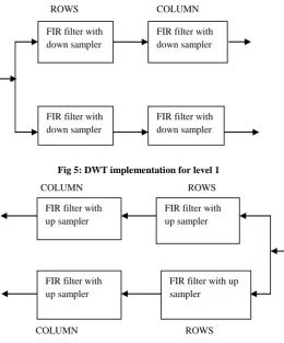
In this proposed architecture, 2-dimensional discrete wavelet transform is implemented for implementation of 2D DWT, first row-wise filtering is performed then the generated sequence is filtered column-wise
[image:4.595.301.562.69.383.2]ROWS COLUMN
Fig 5: DWT implementation for level 1
COLUMN ROWS
COLUMN ROWS Fig 6: IDWT implementation for level 1
Similar implementation has been performed in IDWT. To achieve 2D dimensional filtering, input sequence is initially filtered row-wise then column-wise in DWT and in IDWT, at first the sequence is filtered column-wise then row-wise filtering is performed
5.
RESULTS
Here, the RTL Schematic for implementation of forward DWT, inverse DWT has shown. Also, device utilization summary for implementation of DWT-IDTW is shown.
Fig7: RTL Schematic of Forward DWT 8tap
FIR filter
1 bit counter
register
4 bit counter
8 bit register
Clk
Clk
Data
FIR filter with down sampler
FIR filter with down sampler
FIR filter with down sampler
FIR filter with down sampler
FIR filter with up sampler FIR filter with
up sampler
FIR filter with up sampler
Fig8:RTL Schematic of Inverse DWT
Table2: Device Utilization Summary of proposed Architecture
6.
CONCLUSION
This paper proposes an efficient hardware implementation for DWT using Distributed Arithmetic Architecture. By the use
of Distributed Arithmetic for 8 tap FIR filter implementation with partitioned LUT architecture, the requirement of memory locations is reduced considerably. Further, this technique also possesses an advantage fast computation and less complexity.
7.
REFERENCES
[1] Chao Cheng and Keshab K Parhi .2008.High Speed VLSI Implementation of 2-D Discrete Wavelet Transform. IEEE Transactions on Signal Processing, Vol 56, No 1.
[2] Y.Ramesh Babu, A.Sai. Ramya. Srikala E.,Ramesh B.S.S.V.Jan-June 2014Implementation of Reduced VLSI Hardware Model for 2D Discrete Wavelet Transform,IJEAR.
[3] Ricardo Jose, Colom Palero, Rafael Gadea Girones,Francisco,José Ballester Merelo,Marcos Martinez Peiro,2004,Flexible architecture for the implementation of the two- dimensional discrete wavelet transform(2D-DWT) oriented to FPGA devices,Elsevier, Sciencedirect.
[4] “Fast Discrete Wavelet Transformation Using FPGA and Distributed Arithmetic”.Ali M. Al-Haj, International Journal of Applied Science and Engineering, Year2003, Page(s):160-171.
[5] Yazhini1 and R. Ramesh, 2013,FIR Filter Implementation using Modified Distributed Arithmetic Architecture, Indian Journal of Science and Technology,Page(s):4485-4491
[6] Anand Paul, Bharanitharan K., Sakthivel R,2003, Image denoising by thresholding in the wavelet domain and Implementation in FPGA using VHDL”.ICECS'03 Proceedings of the 2nd WSEAS International Conference on Electronics,Control and Signal Processing, Article No. 68 ,Year:2003,Page(s):467-476
[7] Khan A. Wahid, Md. Ashraful Islam, and Seok-Bum Ko,2011, Lossless Implementation of Daubechies 8-tap WaveletTransform