HEWLETT
f!j
PACKARD·COMPUTER MAINITENANCE COURSE
••••
•••
• ••
•
•••
•
••••••
•
••••
•••••
•
•••
•
•••••
•
••
••••
•
•••
•••
•
• •••
•••••
••• ••••
••••
••••
•
•
••
••••
••
•••
•
•••
•••
•••
•
••••
•
•
•••••
•
•••
•
••
••••
••
•
••
••
•
•
•
••
•••
••••••
•
•
•
•
•••
•
••
• •
••
•
•
HEWLET11-
PACKARD
COMPUTER MAIN1rENANCE COURSE
VOLUME
X\/III
STUDENTS MANUAL
HP 2()OOA
TIME
SHAIRE
SYSTEM
(HP STOCK NO. 5951-1346)
-N
OITICE-The information contained in this manual is for trammg purposes only. Consult the Hewlett·Packard documentation supplied with the computer for current information con-cerning the specific computer system furnished.
The information contained in this publication may not be re-produced in any form without the expressed consent of the Hewlett-Packard Company.
COPYRIGHT HEWLETT-PACKAR D COMPANY 1971
FORWARD
This manual has been prepared by the Cupertino Division Maintenance Training Group. It is intended to serve as an introduction to the HP 2000A Time Share
System. It is hoped that the manual will serve the needs of system operators and
Service Technicians.
This manual was written to help introduce the student to the Time Share Listing, and the Internal Software Reference Specifications. All specific references to the listing are to the 2000A Version "F". Other versions can also be used, although slight differences in page numbers and memory addresses will be experienced.
These previous versions have been corrected and improved. Version F represents
the up-to-date system and it should be in use by all installations. This manual is written from the standpoint of the functional system, with hardware emphasis.
It does not go into detail on the interpreter or software technique.
It is hoped that this manual will take the hardware strengths of the service
tech-nician, and build upon that to provide the technician with an appreciation of the Time Share operating environment. The material is written under the assumption that the computer technician has completed the Basic Maintenance and the Ad-vanced Options Maintenance Training courses. In order to effectively use the list-ings, it is essential that the reader be familiar with the machine language as well as the Assembler.
A system operator without adequate training on the hardware and programming
CONTI::NTS
PAGE
Chapter 1 COMPUTER TIME SHARE 1--1
1--1 Introduction 1 1
1--2 Small Scientific Systems 1 ---1
1--3 Other Mini-Computer Applications 1 3
1--4 Time Sharing 1- 3
1--5 Interpreter 1 4
1--6 Basic Language 1 4
1--7 Response Time 5
Chapter 2 EQUIPMENT 2 1
2--1 Minimum Configuration 2 1
2--2 Switch, Power Fail 2- 1
2--3 Switch, Parity 2 2
2--4 Switch, Disc 2-2
2--5 Optional Hardware 2 5
Chapter 3 SOFTWARE SYSTEM 3- 1
3--1 Multiplexor 3- ]
3--2 Multiplexor Software Module 3 2
3--3 phones 3 4
3--4 System Console 3- -4
3--5 Disc Driver 3 5
3--6 Library 3- 5
3--7 Basic Interpreter 3 5
3--8 Power Fail/Auto Restart 3 6
3-9 Scheduler 3 6
3-10 System Functions 3 6
Chapter 4 MULTIPLEXOR SYSTENI 4 1
4-1 Teleprinter 4 1
4-2 Signal Quality 4 1
4-3 TTY Character Print 4 1
4-4 Multiplexor Data 4 2
4-5 Phones Control 4---4
4-6 Multiplexor Software 4 4
Chapter 5 SCHEDULER 5
5-1 Queue 5 ]
5-2 Queue Exam pIe 5- 1
5-3 Scheduler Loop 5- 4
5-4 Clock Interrupt 5-5
CONTENTS (Continued)
PAGE
Chapter 6 TIME SHARE TABLES 6--1
6-1 Teletype Tables 6- 1
6-2 Directory 6--4
6-3 Equipment Table 6-- 6
6-4 ID Table 6--7
6-5 AD Table 6-7
6-6 File Table 6--7
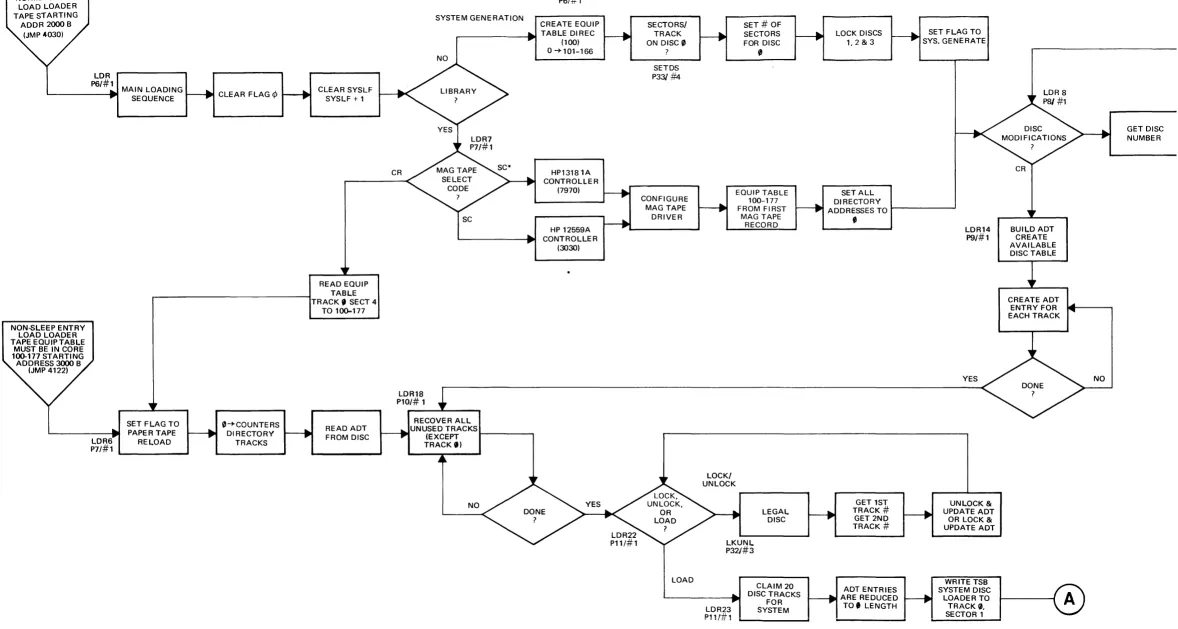
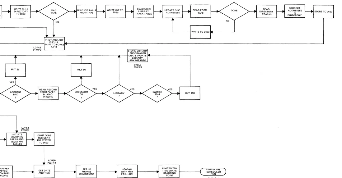
Chapter 7 TIME SHARE LOADER 7--1
7-1 Loader 7 --1
7-2 Paper Tape Load 7 --1
7-3 Awaken from Disc 7-5
7-4 Awaken from Mag Tape 7-5
7-5 System Update 7-6
7-6 Conversion vs Update 7-7
7-7 Loader switch 15 option 7-7
7-8 Non-Sleep Restart 7-8
7-9 Resuscitation 7-8
7-10 Disc Halt 7-8
7-11 Parity Halt 7-9
7-12 Wrap Around 7-9
7-13 Software Loop 7-10
7-14 Operating Halts 7-10
7-15 Loader Halts 7-10
7-16 Key Core Locations 7-11
Chapter 8 TIME SHARE EXAMPLE 8-1
8-1 introduction 8-1
8-2 Multiplexor Example 8--1
8-3 Scheduler Example 8--4
FIGURE
1 2 3 4 5 6 7 8 9 10 11 12 13 14 15 16 17 18 19 20 21
TABLE
2
3 4 5
6 7
LIST OF ILLUSTRATIONS
TITLE
Generalized Computer System
2000A Board Location (2116B Computer) 2000A Board Location (2116C Computer) 2000A Time Share System
Multiplexor Data and phones Multiplexor Flow Chart Queue Exam pIe
Scheduler Loop Clock Interrupt Scheduler (Main Part) Scheduler (SCHED) Scheduler (Swapper) Input/Output Buffering Directory Entries
Logical Disc Information ID Table Entry Format Loader Block Diagram Teletype Serial Data Multiplexor Interrupts Multiplexor Example Scheduler Example
LIST OF TABLES
TiTLE
2000A Minimum Hardware Configuration 2000A Optional Hardware
Disc/Drum Reference Equipment Table
Important Core Locations Contents of Lib (243) Teletype Table
PAGE
] -2 2-5 2-5 3 3 4-3 4-7 5- 2 5-7 59 5---11 5--12 5-13 6--3 6---5 6- 6 6-6 7-2 8---2 8--2 8---5 8 15
PAGE
2 2 :2 3 2 4
6 8
6 10
SECTION INDEX
computer time share
equipment
softwa re system
. "
III
- >
mu Itiplexor system
scheduler
time share tables
"& """., ~ ::::
time share loader
~: ."~" ~
'NlII "
£ '" " .,
time share example
glossary
~ ' ? ' ':'.
1-1 INTRODUCTION
CHAPTER 1
COMPUTER TIME SHARE
The computer has become an integral part of our lives. To the uninitiated, it has almost magical qualities. To a child, the computer seems to have an answer to any question. Often to a service technician with no prior computer experience the com-puter may be an awesome beast. Actually it: can do a certain limited repertoire of instructions rapidly and reliably. Let's look at some of the capabilities to gain an appreciation of the computer 'environment.
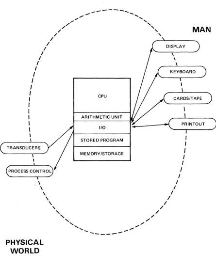
The computer is the center of an operating system with two primary interfaces. One interface is to the physical world. This includes transducer inputs measuring
voltage, temperature, strain, and other physical quantities. It can then control
cer-tain aspects of the environment. It does this by controlling voltage, switch closures,
motor velocity, mechanical positions and other physical quantities. Some of these applications include data acquisition and process control. Figure 1 shows a represen-tation of this generalized computer system.
The other primary interface is with man. Man has vast capabilities for memory, intelligent and rational thought, and decision making. Our communications chan-nels with the computer are somewhat limited however. Visual display and printer output are the primary links used in computer to man output. The man to com-puter input is chiefly a manual operation via the keyboard or punched cards. What is the nature of common computer applications? These are discussed in fol-lowing paragraphs. As we review these it will help in understanding the time share environment.
Throughout the book, we use the word system. It refers to an operating module
requiring both hardware and software. Thus the Time Share system is not so much the equipment which must be purchased, or the paper tapes and listing as it is the personality of the operating environment. To the user, it is the program solution and error messages and response time. To the operator it may be the sleep tapes, the Log on-Log off messages, and status reports. To the service technician it may be the symptoms used to troubleshoot a fault.
1-2 SMALL SCIENTIFIC SYSTEMS
...
---
...,.,.
,...
..."
"
",.
"-",
,
/
,
/
,
MAN
/
,
/
--~\---, / DISPLAY )
I ,
I \
I
I
I
I
I
I
I
,
I
CPU
,
,
I
,
\
\
ARITHMETIC UNIT
I/O - ( ... __ P_R_I_N_TO_U_T _ _ )
I
\ STORED PROGRAM
TRANSDUCERS
MEMORY /STORAGE
\ I
\ I
\ I
PHYSICAL
WORLD
\
,
//
,
,
//
,
,
/",
[image:11.617.105.550.101.652.2]"
.",... ...
'
'"
----_.---..,...
FIGURE 1. GENERALIZED COMPUTER SYSTEM
,
I
I
I I
I
Inputs for this type of service include manual input on a keyboard, punched cards or tape. These can be on-line or off-line depending on the speed or convenience desired, and the operating system available. [f tables or data are required, they may be provided on mag tape, disc or other suitable means.
Since the computer is a binary device with a very limited vocabulary - and is dif-ficult to interface with directly, an operating system is usually provided. This is an optirnized software-hardware system. The stored program modifies the apparent interface, making it easier for man to input or interpret information. Many oper-ating systems and/or languages have been developed to facilitate the interaction with man.
Certain problems occur frequently. Operating systems have been designed speci-fically with these requirements in mind. They include: Disc Operating Systems, Mag Tape Operating Systems, "Batch Mode" systems, and Time Share Systems.
1-3 OTHER MINI-COMPUTER APPLICATIONS
To complete the discussion, we should also consider other applications utilizing mini·-computers. Some are used as data concentrators. These computers interface with a data channel by performing some preliminary processing which im prove the effectiveness and decrease the cost of the data line. Sometimes the computer is dedicated to a specific task, such as the controller of a test stand. A Fourier Analyser is another example of a dedicated computer. It receives physical input in the form of time and magnitude while performing mathematical operations and provides a frequency and magnitude output. Other applications include Fire Con-trol applications, traffic contro], high speed transportation conCon-trollers, ticket booking services, etc. The reader can undoubtedly add many other applications from his own experience.
1-4 TIME SHARING
A certain class of computer applications has arisen enough to warrant designing a special operating system and a special language. The language is BASIC. The operating system varies with the manufacturer and his hardware capability. The requirements are characterized by small data base requirements and straight for-ward computational requirements. In the generalized computer system diagram,
figure 1, the interface is typically a keyboard for both input and output.
Under these circumstances, the computer (Central Processor Unit) has a great deal of spare time when servicing a single user. The operating system allows multiple users access to the system in a quasi-simultaneous manner; hence, the name Time Share.
1-5 INTERPRETER
Perhaps we should say a word about the Interpreter. A compiler translates symbols meaningful to the programmer into machine language code. Fortran or Cobal are examples of common compiler languages. In both cases, machine language code is gelierated in absolute or relocatable code, and the program is run. An Interpreter takes the symbolic statements one at a time, executing them in the proper order-but without generating any machine language program code.
The BASIC on-line interpreter checks for syntactical errors, wrong data type, missing delimiters and other common type errors. It provides error messages immediately. This allows the user to correct the program statements and try again. The on-line error messages and immediate correction feature provides a real benefit for the writing and debugging of a program.
The interpreter converts the program statements to a compiled format. This is a more efficient coding or symbolic representation for the program statements. The system makes use of this as well as syntax stacks, pointers and linkages. But this is not machine code, and the computer does not execute these statements in the normal machine language sense.
1-6 BASIC LANGUAGE
The HP 2000 family makes use of the "BASIC" language. This is a powerful conver-sationallanguage using English words and common mathematical symbols. Basic
stands for ~eginners All-purpose Symbolic instruction Code. It was developed at
Dartmouth University in 1964 under the direction of Professors
J.
G. Kemeny andT. E. Kurtz.
Its simplicity along with the use of common English words and its free form input makes it easy to learn and use. Yet the strings, files, and matrix capability makes it powerful and effective.
The on-line feature provides error diagnostic messages both at program writing time and at Run time. This certainly assists the beginning programmer in learning and using the BASIC language. Although the language is easy to use, it does provide a powerful programming capability. The manual" A Guide to Time Shared Basic", HP Stock Number 02000-90002, is useful both as a reference and for self instruction.
An extensive library of programs is available for the HP 2000 Time Share Systems. These include applications in business and finance, engineering and scientific, math-ematics, statistical analysis, educational, utility, and demonstrations and games.
1-7 RESPONSE TIME
One of the primary limitations of many computer systems is the speed of the I/O devices. In Time Share applications, the most common terminal used is the tele-printer. Its maximum speed is 10 characters per second. This data speed is compa-tible with a voice quality telephone line. It is not much of a challenge to the CPU, however. The system accepts input data from all teleprinters. At the end of each input line, an individual user is given high priority. The system determines the nature of the input and services it rapidly. This enables the user to continue with his next line and the system appears quite responsive.
In output operation, the system fills an output buffer for the user. It continues to
process all outputs through the multiplexor routine. If the system fills an output buffer and cannot continue the user goes into output suspend. The multiplexor routine requires very little additional processor time and keeps a steady output to all users. When the buffer gets low the system again schedules the user and re-sumes his program. With this technique, the user receives a fairly steady output rate, and still the processor can service other users too.
The system achieves this responsive nature by establishing the priority for tasks. The maximum time slice allowed for any user when others are queued up awaiting service is 1.0 second. A user who had used up his maximum time period and had not completed his program would then be placed at the bottom of the queue.
Every 0.1 second, the system scans all inputs to determine whether some one had completed a line and was awaiting service. Priority is established to optimize re-action time. Highest priority is given to syntax lines, user requeued after I/O suspend, and then continuing programs during the time allowed. Next the core resident programs called by the system (SCRatch, TAPe and KEY) and called by BASIC (RUN, LISt and PUNch). The Disc resident programs including those called by a user and those called by the system operator are assigned the third priority. The lowest priority is assigned for the users who have expended their time allo-cation without completing their program.
The result of assigning priorities in this man::1cr is a system that responds to a user very rapidly. In most situations, a user will not notice the delays. Typical delays for syntax lines are in the order of one second or less.
The largest delays are experienced when allrerminals are being used for CAl
exercises. In this case, everyone is executing a program. A significant number of
input suspensions occur. These tend to speed up the system since each user does not require his full time allocation at one second. The nature of the exercise has a lot to do with the delays experienced. Delays of two to four seconds are common. Occasionally substantially longer delays may be encountered.
CHAPTER 2
EQUIPMENT
The 2000A Time Share system requires a wide range of equipment and options. Some are required, others are optional. Even in the required list, certain substitu-tions can be made.
2-1 MINIMUM CONFIGURATION
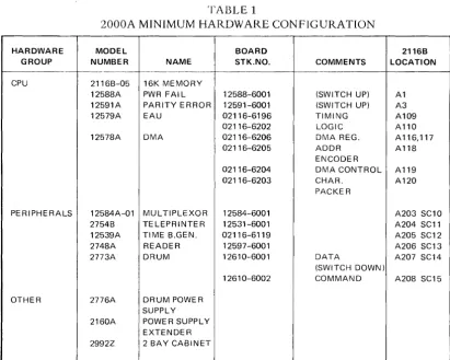
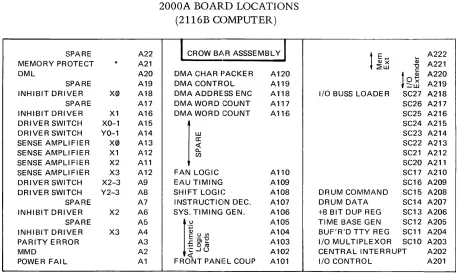
The minimum hardware configuration for the HP 2000A system is shown in Table 1.
The slot for all CPU options is fixed. The I/O slot for these minimum configuration peripherals is also fixed. The slot designators for Table 1 correspond to the 2116B comlputer. Figure 3 shows the specific locations in the 2116C computer.
This minimum configuration shows the 2773A Drum. Actually any Disc or Drum from TAble 3 would be satisfactory.
It is expected that the reader is familiar with the equipment used in the HP 2000A. And further, that he has available the instrument manuals. We need not describe their general function and purpose. There is more detailed information on the multiplexor hardware in Chapter 4.
The next three sections deal with the positions of the switches in the HP 2000A. Their positions are important. The instrument manuals describe the individual function but do not indicate the req uired position for a particular operating sys-tem.
2-2 SWITCH, POWER FAIL
The Power Fail board has a switch which defeats the automatic restart feature. This switch must be up to allow restart. If the switch is down and the computer experiences a momentary power failure, a halt f.}at P=31141 will be experienced. When power is restored, the computer may come up at some random address. If
the switch is raised to the up position, it will restart.
2-3 SWITCH, PARITY
The Parity check board has a switch that forces an immediate halt when up, or allows an interrupt to the trap cell if down whenever a parity error occurs. The immediate halt is caused by PEH signal clearing the RUN 1 flip flop. The Parity Error light on the front panel will be illuminated indicating the parity error con-dition. An interrupt mode exists with the switch down. A parity error occurring during a DMA transfer (core to disc) will be ignored. Because of this limitation it is essential that the switch on the Parity board be up in halt mode.
2-4 SWITCH, DISC
The Disc interface has a track protect switch. This allows read only operation from the protected tracks. The switch is located on the Data board. This switch must be down in unprotected position for the Time Share system allowing read/write capa-bility on all tracks.
The protected tracks always include track zero (additional tracks are protected by removing additional diodes). The Time Share system must have access to track zero so the switch must be down.
TABLE 1
2000A MINIMUM HARDWARE CONFIGURATION
-...
-HARDWARE MODEL BOARD 2116B GROUP NUMBER NAME STK.NO. COMMENTS LOCATION
- -~--"---"---_ ..
CPU 2116B-05 16K MEMORY
12588A PWR FAIL 12588-6001 (SWITCH UP) A1 12591A PARITY ERROR 12591-6001 (SWITCH UP) A3 12579A EAU 02116-6196 TIMING A109
02116-6202 LOGIC A 110 12578A DMA 02116-6206 DMA REG. A 116, 117
02116-6205 ADDR A118 ENCODER
02116-6204 DMA CONTROL A119 02116-6203 CHAR. A120
PACKER
PERIPHERALS 12584A-01 MUL TIPLEXOR 12584-6001 A203 SC10 2754B TELEPRINTER 12531-6001 A204 SC11 12539A TIME B.GEN. 02116-6119 A205 SC12 2748A READER 12597-6001 A206 SC13 2773A DRUM 12610-6001 DATA A207 SC14
(SWITCH DOWN)
12610-6002 COMMAND A208 SC15 OTHER 2776A DRUM POWER
SUPPLY 2160A POWE R SUPPLY
[image:18.617.101.513.324.653.2]TABLE 2
2000A OPTIONAL HARDWARE
DESCRIPTION
Mag Tape
Telephone-Auto Disconnect Keyboard-Display Terminal
MODEL HP 3030G HP 7970A-200 HP 7970A-202
12584B-001 2600A
INTERFACE
12559A 13181 A-001 13181 A
None required
DISC/DRUM
Drum (393,216 words) (786,432 words) (1,572,864 words)
Disc (1,048,576 words) (786,432 words) (524,288 words)
.. HP 2776A Power Supply .... HP 2772A Power Supply
2773A *
2774A 2775A 2776A-004 * *
2776A-003 2776A-002
2-5 OPTIONAL HARDWARE
12610B
12610B
(60K Char/Sec) (20K Char/Sec) (30K Char/Sec)
48 tracks/128 sectors 96 tracks/128 sectors 192 tracks/128 sectors 128 tracks/128 sectors 96 tracks/128 sectors 64 tracks/128 sectors
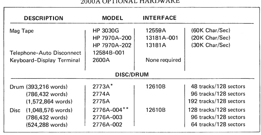
Table 2 shows the optional hardware avaij!able for the 2000A System. Three differ-ent mag tape units are available. The interface requires two adjacdiffer-ent I/O slots. These can be located in any slots starting at SC16 (A209). The Mag Tape command tells the system which unit is being used (i.e. tv1AG TAPE-22* indicates the 13181A Controller for 7970 because of the asterisk following the Select Code. Mag Tape-22 indicates the 12559A controller for the 3030.)
The Telephone Auto Disconnect option is. required whenever the system contains a telephone Data Set like the 103E series. In the 2000A the board can be plugged into any available I/O slot. The PHOnes command gives the select code information and the number of seconds allowed for log on (i.e., PHONES-26,240).
A Keyboard Display unit (HP 2600A) is available. It can be used in place of the 2749A Teleprinter. It is usuable either hardwired, or connected through an acoustic coupler. In both cases, it can operate at a higher transmission data rate than the teleprinter.
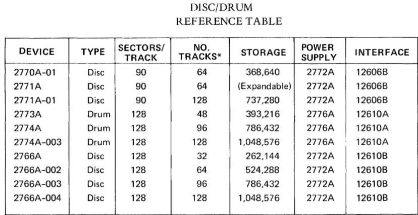
Various Drum and Disc units are available. These are shown in Table 2. These can
be substituted in place of the Drum on thl.~ minimum configuration list for larger
[image:19.612.94.510.81.297.2]DEVICE TYPE SECTORS/ TRACK
~----
r---2770A-01 Disc 90
2771A Disc 90
2771A-01 Disc 90
2773A Drum 128
2774A Drum 128
2774A-003 Drum 128
2766A Disc 128
2766A-002 Disc 128 2766A-003 Disc 128
2766A-004 Disc 128
, "
-TABLE 3
DISC/DRUM REFERENCE TABLE
-- -.
NO.
STORAGE POWER
TRACKS* SUPPLY
64 368,640 2772A
64 (Expandable) 2772A
128 737,280 2772A
48 393,216 2776A
96 786,432 2776A
128 1,048,576 2776A
32 262,144 2772A
64 524,288 2772A
96 786,432 2772A
128 1,048,576 2772A
INTERFACE
12606B
12606B
12606B 12610A
12610A
I
12610A
12610B
12610B 12610B
12610B
[image:20.615.109.523.65.278.2]SPARE A22 MEMORY PROTECT * A2l DML A20 SPARE A19 INHIBIT DRIVER X0 A18 SPARE A17 INHIBIT DRIVER X1 A16 DRIVER SWITCH XO-1 A15 DRIVER SWITCH YO-1 A14 SENSE AMPLIFIER X0 A13 SENSE AMPLIFIER X1 A12 SENSE AMPLIFIER X2 Al1 SENSE AMPLIFIER X3 A12 DRIVER SWITCH X2-3 A9 DRIVER SWITCH Y2-3 A8 SPARE A7 INHIBIT DRIVER X2 A6 SPARE A5 INHIBIT DRIVER X3 A4 PARITY ERROR A3 MMD A2 POWER FAIL Al
*Optional, not required.
INHIBIT DRIVER A22 X-V DRIVER A21 SSA A20 SSA A19 X-V DRIVER A18 INHIBIT DRIVER A17 MEMORY PROTECT* A16 PARITY ERROR A15 MAD A14 MOB A13 INHIBIT DRIVER A12 X-V DRIVER A11 SSA A10 SSA A9 X-V DRIVER A8 INHIBIT DRIVER A7 POWER FAIL A6 DMA CHAR PACKER A5 DMA CONTROL A4 DMA ADDRESS ENC A3 DMA WORD COUNT A2 DMA WORD COUNT A1
[image:21.612.84.543.66.340.2]*Optional, not required.
FIGURE 2.
2000A BOARD LOCATIONS (2116B COMPUTER)
1
CROW B.ll.R ASSSEMBLYI
DMA CHAR PACKER A120 DMA CONTROL Al19 DMA ADDRESS ENC A118 DMA WORD GOUNT A117 DMA WORD GOUNT A116I
~
FAN LOGIC A110 EAU TIMING A109 SHIFT LOGIC A108 INSTRUCTION DEC. A107 SYS. TIMING GEN. Al06
It.~
A105A104 .c:: OJ .... A103
~oro
''::: -' () A102
<t:
[image:21.612.87.544.403.691.2]FRONT PANEL COUP A101
FIGURE 3.
2000A BOARD LOCATIONS (2116C CO!v1PUTER)
I
CROW BA.R ASSEMBLYI
UJ
a:
<t:
a..
(f)
EAU LOGIC A110 EAU TIMING A109 SHIFT LOGIC A108 INSTRUCTION DEC. A107 SYS TIMING GEN A106
r
'':; A105( l ) U V l A104
E'-"0
£gffi A103
''::: -' ()
A102 <t:
FRONT PANEL COUP, A101
1
E ( l ) x ~ .... (l) A222 A22l~UJ "0
c:: A220
lO~
::::UJ A2l9I/O BUSS LOADER SC27 A2l8 SC26 A217 SC25 A216 SC24 A215 SC23 A214 SC22 A2l3 SC21 A212 SC20 A211 SC17 A210 SC16 A209 DRUM COMMAND SC15 A208 DRUM DATA SC14 A207 +8 BIT DUP REG SC13 A206 TIME BASE GEN SC12 A205 BUF'R'D TTY REG SC1l A204 I/O MULTIPLEXOR SC10 A203 CENTRAL INTERRUPT A202 I/O CONTROL A201
SPARE .... SPARE (l)
"0
lo~
A220::::UJ A219
CHAPTER 3
2000A SOFT\NARE SYSTEM
The 2000A Time Share System consists of 5,ix modules. The modules are in abso-lute fornlat (not relocatable). They have limited ability to communicate with each other. The scheduler might be considered the master control program. We shall look briefly at each of these modules. Refer to Figure 4 for a representation of these modules. Those six modules consist of the multiplexor, system console, disc driver, library, Basic interpreter, and scheduler.
The understanding of the relationship between these Time Share System modules is essential. We might consider the primary purpose of the HP 2000A to execute the user program or user command (like RENumber). Incidental to this is the pro-cess of inputting program statements, providing syntax checking, error messages and these other services. In either case the executing program is a portion of the Basic Interpreter or the Library program. We might consider these as foreground activities.
It is first necessary to swap the users swap track to the user swap area in core.
The actual swap is made on a cycle stealing basis with DMA. There may also be required communications through the multiplexor. The scheduler does the check-ing and schedulcheck-ing for all pendcheck-ing activities. These activities might be considered background or overhead.
We do not wish to make these definitions more rigorous, and would prefer not to examine them too closely. What we are trying to do is first provide an intuitive feel for the different modules, their purpose, and the manner in which they share the available CPU time.
3-1 MULTIPLEXOR
The teleprinters are input-output devices. The data format is the 8-bit ASCII code embedded within three other start and stop bits. Communications between the tele-printers and the system is handled in bit serial manner.
3-2 MULTIPLEXOR SOFTWARE MODULE
The multiplexor software module makes use of the TTY Tables and buffer areas. Each port has an associated teletype table containing temporary storage for pointers, time counters, status, priority, etc. The buffer areas provide temporary storage for input and output communications with each teleprinter.
The multiplexor system handles the character input bit-by-bit, stacking the charac-ters into the proper buffer area. It processes the special characcharac-ters as it goes, such as backspace and alt-mode. When the carriage return indicates the end of the line, the multiplexor sets a bit in the status word used by the scheduler. The next time through the scheduler the proper action will be determined and the user will be placed on the queue.
Up until the final character in the line, all of the necessary processing has taken
place within the multiplexor module. It operates under interrupt mode using only
the necessary time required for the bit-by-bit and character-by-character pro-cessing.
Similarly, in output mode, a Library module or the basic module will provide put rapidly filling the buffer area. The multiplexor system then processes the out-put character-by-character and bit-by-bit. This may be likened to a background-foreground mode of operation. All communications are handled essentially in parallel in the background. This requires a certain amount of time and appears as system overhead. In the foreground the Time Share system is working with one individual user at a time.
The multiplexor operates on a statistical basis. There are 8 interrupts per bit, and 11 bits per character. Thus, with 88 interrupts per character, it is highly unlikely that all teleprinters would start a character at the same instant.
Normally, the processing load of the multiplexor is distributed fairly evenly be-tween the various interrupts. The overhead due to processing the multiplexor interrupts (when no user is being serviced) is about 90 microseconds. This re-presents about 8% of the available CPU time. The module requires about 160 microseconds to service a new character, 80 microseconds to process each bit, 245 microseconds for end of character. Additional time is required for special character (i.e., alt mode, carriage return, backspace, etc.)
14000
BASIC INTERRUPTER
1240
USER
SWAP AREA
37300
LIBRARY
~
-~
~
~
34107
SCHEDULER
30740
DISC DRIVER
SYSTEM CONSOLE DRIVER
DATA SET
~i
IkJ~
~~/~GOUSTIC
. §' COUPLER
3-4
3-3 PHONES
The phones routine handles the control signals for the Bell Telephone Model103
data set. It provides the proper time for initial log on. It also handles inadvertant
disconnect. Although it is shown as a separate module, it is just a small portion of the scheduler.
3-4 SYSTEM CONSOLE
The system console provides a means of controlling the hardware system. The 2754B Teleprinter is interfaced with an HP 1253lB Interface Card. The system console is used for four functions. First it allows control over user ID. This is done by adding new ID's, killing ID's, changing passwords, resetting time clocks, and controlling the allocation of disc space and allowable time. Second it is used for hardware control. This includes the DISc, MAG tape, PHOnes, LOCk and UNLock commands and the ROSter and STAtus requests.
The third function deals with program control. These commands include the DIRectory listing and the REPort listing all ID's with time and disc usage. PURge command allows cleaning up old programs which have not been used recently. SLEep command is used to save a tape copy of the system and all library and
directory programs. It also provides a compaction of available disc spaces.
The fourth use of the system console provides log-on log-off messages to support the accounting and billing procedures. Since the logging is such an important func-tion, the teleprinter punches a paper tape back up for all log-on log-off messages. The logging functions are of high priority, because they directly affect the system response time to the user, so these messages interrupt routine functions such as a DIRectory print, STAtus, or REPort.
The system console software module is operated under the interrupt mode. It uses
two flags T35FI and T35F2 to keep track of its current operating mode. T35F2 must be zero to allow input. The 36 word buffer is used for both input and output buffering.
Library routines can use the buffer by setting T35F2 thus inhibiting any input. In addition to the separate console driver significant coding exists within the scheduler. This portion deals primarily with setting up the log buffer, and in setting up the queue entry for the system console.
3-5 DISC DRIVER
The fourth software module is the Disc Driver. The Time Share system makes full use of the fixed head disc or drum. All disc transfers are made under DMA control. The computer memory size limits the systern to only one user at a time. Each user (port) has one dedicated swap track on the disc. As a user reaches the top of the queue, the scheduler initiates the disc to core transfer. This brings in 85 sectors replacing the previous contents of the core swap area. The disc driver also writes the user core swap area to the disc swap track, or brings in the 4 sectors associated with each library program to the library core area starting at address 37300.
The disc driver is entered with the A and B registers containing the disc and core address. The location WORD contains the number of words to be transferred. A status location ENDSK is set at the beginning of the transfer, and is cleared at the completion of the transfer. Its condition indicates whether a transfer is underway.
3-6 LIBRARY
A 256 word segment of core is used by the various library programs. The origin address is 37300. There are more than 30 of these programs. They are disc resi-dent, and are brought in whenever needed to this 256 word library area. In certain cases, the program exceeds the 256 word limit. This is handled by breaking the program into segments and executing the program and overlay sequentially. These programs are absolute. They can call other programs as necessary. For example: Save can call Supersave, and Hello program will search the library for $Hello executing it upon process completion.
It should be apparent that the use of a disc and the availability of these library programs has added a significant amount of power and sophistication to the system capability compared to Single Terminal Basic capabilities.
3-7 BASIC INTERPRETER
The Basic Interpreter is the heart of the software system. It is comprised of many
functional subsections. These include syntax checking, compile and decompile, error routines, generation of symbol tables, formula evaluation, arithmetical rou-tines, utility rourou-tines, and the program execution loop. This entire program uses only slightly more than 6600 words of memory.
One of the most significant problems to be overcome was the multi-entry nature of the compiler. This allows a users program to terminate at any point in the com-piler. When he works up through the queue, the compiler can continue the execution again at the proper place. To accomplish this certain pointers and stacks had to be included in the user swap area.
The actual user program is maintained in the core user swap area. This area consists of 5440 words of memory. The swap area has various sub-routine pointers, value tables, symbol tables, syntax stacks, etc. All of these are of syntactical nature.
They are not computer programs. The computer P register should never be executing
3 6
The program may be in the uncompiled mode. This is the regular English language form as the program is initially entered. When the user types RUN, the program must be complied. This is a translation to a symbolic form required by the interpreter.
3-8 POWER FAIL/AUTO RESTART
The Time Share system requires a software module to service the power fail
condi-tions. It is not considered one of the system software modules because of its
spe-cialized nature.
3-9 SCHEDULER
The sixth system module is the scheduler. This is the executive module. It handles
the service requests from the other modules. It is responsible for making good use
of CPU time.
The scheduler is entered every 100 milliseconds by an interrupt from the Time Base
Generator. It is also entered whenever the interpreter module completes its task.
Let's look at the various functions performed by the scheduler.
The Time Base Generator interrupt is serviced. The time of day counters are updated and serviced in case of roll over. The timer for a user is updated. The swap out is initiated if the users time slice is exhausted.
The queue is an ordered list of users awaiting service. It is maintained on a priority basis. The scheduler inserts new entries, and removes those who are done. It removes those who have exhausted their time slice and re-inserts them at the proper priority.
As the scheduler works through, it checks the status of the multiplexor through the
MPCOM word, the phones input for changes or time outs, the system console through its flag words, and the logger request.
3-10 SYSTEM FUNCTIONS
l.Jet's consider the relationship between these system functions. The multiplexor handled the bit by bit and character by character transfer until the carriage return was detected. Then the user's flag was set in the MPCOM word indicating service required. The input line was placed in the appropriate buffer, and the pointers are available in the TTY tables. There are various reasons for a service request. These
include a command or syntax statement, output buffer down to 10 characters on
an output wait, input provided following an input wait, or a user abort. The response may require initializing a library program or entering the interpreter, or it may be
to continue a program suspended for I/O wait. In any case, it will require placing
the user on the queue.
The phones processing is simple. It looks at the ringing and carrier lines from the
data set. A change in the status (or voltage level) of these lines requires service.
The action required is normally to provide the Data Terminal Ready signal, or
to remove it. In the event of unintentional disconnect, the log off procedure is
The system console has an associated buffer for input and output. A logger buffer also exists for log on and log off messages. A log on/off message will be placed in the logger buffer. If the console is quiet, the log message prints. If the console was actively outputting a print (as in DIRectory or STAtus), the logger message waits until the completion of the current line before gaining control.
CHAPTER 4
MULTIPLEXOR SYSTEM
The multiplexor system provides a means to link the computer to the teleprinters.
The input to the Time Share syst~m may be syntax statements, commands, or data
input. The output will be program messages~, error messages, command completion,
etc. The multiplexor is the communications link. We will consider the characteristic of the elements within this system.
4-1 TELEPRINTER
The teleprinter is an electro-mechanical device. The main shaft is driven by a syn-chronous motor. This establishes the data rate, and all data to and from the tele-printer must be synchronized at this rate.
The teleprinter uses an eight level ASCII code. ASCII stands for an industry adopted standard code called the American .s.tandard Code for Information Lnterchange. The code requires 7 bits for data and the eighth is an optional parity bit. These eight ASCII bits are preceeded by a start bit (logic zero level) and followed by two stop bits (logic one level). The data rate is 10 characters per second. The time period for a full character is 100 milliseconds. Each bit requires about 9.09 milliseconds.
4-2 SIGNAL QUALITY
The signal output will seldom be an ideal pulse train. Noise bursts and pulse deterio-ration due to long transmission lines or telephone circuits will reduce this quality. Time synchronism will not be exact. The best time to sample a bit will be somewhere near the middle of the bit.
4-3 TTY CHARACTER PRINT
In LINE mode pushing a key will initiate the generation of the pulse train and will result in a complete rotation of the main shaft. The character will not print auto-matically however. An electrical signal must be sent back to the teleprinter from the computer in order to print a character. This is referred to as an echo.
Let us digress a moment and see how this works. In LOCAL mode depressing a key moves the code bars under the keyboard setting up switch conditions for the 8 data
bits. It also initiates one rotation of the shaft. The switches place voltages on the
Finder" adjustment, and the armature spring tension and setting. These adjustments should be attempted only by qualified technicians. If misadjusted occasionally a char-acter may misprint even though the proper data has been received by the computer.
4-4 MULTIPLEXOR DATA
How does the hardwired teletype work from a data flow concept? See figure 5 for the multiplexor data and phones information. Tne interrupt CIrCUIt on the multi-pLxor assembly generates computer interrupts. These interrupts allow synchron-ization with the teleprinter data train. We need to locate the center of the bit, thus
requiring more than one interrupt per bit. It would be desirable to spread the
tele-printer servicing over various interrupts so a1116 units would not likely require simultaneous servicing, An interrupt rate of 880 cycles per second was selected thus giving 8 interrupts per bit.
Figure 5 shows one teleprinter. Its cable can be attached to anyone of the 16
con-nectors (J0 to J15). In the event a data phone is used, the teleprinter would plug
into an acoustic coupler. It would make an acoustic coupling with the telephone
hand set to the telephone network. The telephone network would terminate in a 103 type data set which would then plug into the multiplexor connector (instead of the teleprinter cable).
The physical wiring on the multiplexor should be described. The Data lines are
wired on the connector chassis from each port connector to J17. A Data cable
(12584-6005) then takes all of these connections from J17 to the multiplexor
Data board in I/O slot 10.
The Ringing and Carrier signals are routed from each of the 16 connectors to the Ring Carrier assembly which is mounted directly behind the connector chassis.
The ring or carrier connections are then routed to J16. The cable (12584-6008)
then takes these signals to the multiplexor phones board which can be located in
any available
I/O
slot SC16 or above. The Data Terminal Ready signal then returnsthrough the cable and J16 to the individual port.
The incoming data from the teleprinter is routed through the multiplexor panel to the multiplexor data board. The input circuits monitor the voltage levels of each of the 16 lines. The computer uses the LIA/B instruction to input the data levels. Each Port is associated with one of the 16 bits of the computer word.
[t should be noted that the input circuit inverts the logic level. The start bit for character is a logic zero at the teleprinter. After being inverted on the multiplexor data card, it is a logic one at the I/O slot.
It is up to the multiplexor software to recognize the initial change of state from
a zero to a one as the start of a new character. It counts 4 interrupts to the middle
of the bit. It then begins to send the output data back to the teleprinter to allow
n
c::
w
~
:::)
c..
:2E
o
u
(
I
OSCI
~I ST6~~~E
FLAG ANDh
IRQCLF
STC
INT. FLG INTERRUPT
LlAIB INPUTDATA DATA RECEIVED IOBIX BITX
INPUT 16 CIRCUITS
OUTPUT 16 CIRCUITS
o
TAIB OUTPUT DA T A lOB OX BIT XSELECT 12584-6001
CODE
10
~---~
MULTIPLEXOR DATA
r---,
I
I
l
OSC AND FLAG UNUSED II I
1. _ _ _ _ _ _ _ _ _ _ _ _ _ _ ..J
INPUT
LlAIB STATUS CARRIER /OR/ RINGING IOBfX BfT X
INPUT 16 CIRCUITS
OUTPUT 16 CIRCUITS
OTAIB STATUS OUTPUT IOBOX BIT X
12584-6001
MULTIPLEXOR PHONES
!::;(
)
~(
)
~(
)
~(
)
~(
)
~(
""I '\ ~~(
~(
)
~(
)
!:;(
)
~(
)
~(
)
12584-6002MUL TIPLEXOR PANEL
C/)
!::
:::> u 0:: U
<.0
--1
«
u
a..
>
I-12584-6011
RING CARRIER INTERFACE
FIGURE 5. MULTIPLEXOR DATA AND PHONES
3-3 PHONES
The phones routine handles the control signals for the Bell Telephone Model103
data set. It provides the proper time for initial log on. It also handles inadvertant
disconnect. Although it is shown as a separate module, it is just a small portion of the scheduler.
3-4 SYSTEM CONSOLE
The system console provides a means of controlling the hardware system. The 2754 B Teleprinter is interfaced with an HP 1253lB Interface Card. The system console is used for four functions. First it allows control over user ID. This is done by adding new ID's, killing ID's, changing passwords, resetting time clocks, and controlling the allocation of disc space and allowable time. Second it is used for hardware control. This includes the DISc, MAG tape, PHOnes, LOCk and UNLock commands and the ROSter and STAtus requests.
The third function deals with program control. These commands include the DIRectory listing and the REPort listing all ID's with time and disc usage. PURge command allows cleaning up old programs which have not been used recently. SLEep command is used to save a tape copy of the system and all library and
directory programs. It also provides a compaction of available disc spaces.
The fourth use of the system console provides log-on log-off messages to support the accounting and billing procedures. Since the logging is such an important func-tion, the teleprinter punches a paper tape back up for all log-on log-off messages. The logging functions are of high priority, because they directly affect the system response time to the user, so these messages interrupt routine functions such as a DIRectory print, STAtus, or REPort.
The system console software module is operated under the interrupt mode. It uses
two flags T35FI and T35F2 to keep track of its current operating mode. T35F2 must be zero to allow input. The 36 word buffer is used for both input and output buffering.
Library routines can use the buffer by setting T35F2 thus inhibiting any input. In addition to the separate console driver significant coding exists within the scheduler. This portion deals primarily with setting up the log buffer, and in setting up the queue entry for the system console.
During output when the bit timer rolls over the new bit must be sent out. When character roll over occurs, the buffer pointers are incremented and the new character is prepared, While in output wait the number of characters are checked. If 10
characters remain the MPCOM bit is set to reschedule the user.
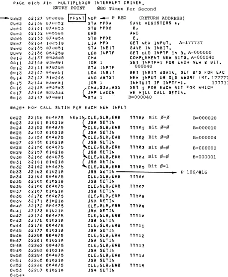
The flow chart is roughly proportional to the time required by the multiplexor driver. The oscillator frequency of 880 hertz was selected to distribute possible end of character processing over the various interrupts. Decreasing the oscillator frequency would slightly reduce multiplexor overhead. But the number of users (per interrupt) requiring service would increase. The multiplexor board has a special
flag and interrupt circuit. It has a storage flip flop which retains an interrupt
oc-curring before the completion of the multiplexor routine. It virtually doubles the
MPXNT
P185/#16
STORE REGISTERS
NO
SHIFT RIGHT
INPUT NEW MPX DATA
GET TTY #
SETIN
P186/#16
SAVE IN INBIT
PUT: BTIM, STAT, ABCN,
MASK ON BASE PAGE
ADD NEW INPUTS
1----61 TO IN PTF t----i~
YES
NO
YES
YES
NO
LADDR
P1871#16
NO
T NEW DATA
"TTY#
SAVE IN INBIT
PUT: BTIM, STAT, ABCN,
MASK ON BASE PAGE
I
I
ADD NEW INPUTS
t---__
TO INPTF I---acYES
NO
YES
P187/#16
NO
LADDR
P187/# 16
YES
NO
NO
MAKE ISZ FOR LADDE R ENTRY
YES
ALREADY SET
UP SET5
SETa IN ABTST
INCREMENT ABORT COUNTER
PUT-100 IN ABCN
SET3
RESET INPUT FLAG
TO ALLOW MORE INPUT
SET BIT ABTST
STORE ISZ
-4 TO BTIM
BITTIMER
~1a TO BeNT
BIT COUNTER
LADDR P187/ #16
PUT: BPNT, BSTR, BHED, BGIN, BEND ON BASE PAGE
INP.6
P191/ #16
ADD CHARACTER
TO BUFFER
INCREMENT BIT TIMER
POSITION CHARACTER
BITS' TO 6 & MASK OFF
TAKE CARE OF BUFFER WRAP AROUND & CHARACTER
PACKING
FIGURE 6. MULTIPLEXOR FLOW CHART
NO
CHANGE LADDER ENTRY FROM ISZ
BACK TO JMP *+4
RETURN TO
'-, ____ L_~_.D_D_~_. __ ~"
OUTPUT NEW DATA TO MPX
LOAD B BTIM ADDR
MPXIO
Pl89/# 16
RESET INPTF FOR MORE INPUT
NO
RESTORE REGISTERS
-8 TO BTIM
SETINPTF TO PREVENT
FURTHER INPUT
CLEAR FLAG ON MPX
PUT: CPTR, BCNT, MASK OR BASE
PAGE
RESET BSlR
SET MPCOM
BIT
JMP, 1 TO PREVIOUS
LOCATION
TEST CHARACTERS
RESET ESCAPE
FLAG
NO
IF FULL DUPLEX PUT 1> IN
MPOUT
P192/ #16
INP.5
PROCESS BACKSPACE
SET MPCOM
BIT
PUT 1 IN MPOUT
ADD 1 BIT TO CHARACTER
ROTATE CHARACTER INCREMENT BIT COUNTER
PROCESS ESCAPE ALT MODE
ADD SLASH
& CRLF TO BUFFER
~-- ~
~
JMP,l TO PREVIOUSLOCATION
NO
ES
T
~
SET
TEST CHARACTERS
RESET ESCAPE
FLAG
NO
IF FULL DUPLEX PUT <P IN
MPOUT
P192/ #16
INP.5
PROCESS BACKSPACE
SET MPCOM
BIT
PUT liN MPOUT
ADD 1 BIT TO CHARACTER
ROTATE CHARACTER INCREMENT BIT COUNTER
PROCESS ESCAPE ALT MODE
ADD SLASH
& CRLF TO BUFFER
SET IOTOG
TO OUTPUT -4 TO CCNT
RETURN TO LAODR
OUTPT
P193/#16
NO
~
r l
~~~~~E
h
I
JCOMPARE WITH ... _~
1 - - -... PREVIOUS BIT
INCREMENT BIT COUNTER
OUT.2
P194/#16
INCREMENT BUFFER
WRAPAROUND
IF END OF GET NEW
POSITION AND
NO
ADD START &
STOP BITS
-11 TO BCNT
INCREMENT CHARACTER COUNTER
CHECK STATUS 1----..1..c::
NO
HANGE IIPOUT
(ES
INCREMENT BIT COUNTER
GET NEW CHARACTER
POSITION AND MASK
NO
ADD START &
STOP BITS
-11 TO BCNT
INCREMENT CHARACTER COUNTER
CHECK STATUS t--___ K
NO
RESTORE
JMP *+4
TO LADDR
IOTOG TO INPUT
RESETINPTF TO ALLOW
INPUT
NO
SET MPCOM
BIT
RETURN TO LADDR
CHANGE TO IDLE
RESET ALL BUFFER POINTERS TO BGIN
CHAN6E INPTF TO INPUT
RETURN TO LADDER
FIGURE 6. MULTIPLEXOR FLOW CHART
CHAPTER 5
SCHEDULER
The Scheduler is the Time Share Executive. A review of figure 4 shows the signi-ficant relationship between the scheduler and the other modules. The Queue is an ordered listing of all users desiring to be serviced. It is the servicing of the queue, including the status and priority, which constitutes the primary function of the scheduler.
The scheduler calls the Disc to effect a swap from the disc to core or from core to
the disc. It controls the transfer to either the Basic intrepreter or to the library. The
multiplexor is a self contained driver. It is entered by the interrupt from its
oscil-lator. It handles communication from the teleprinter to the buffer or from the
buffer to the teleprinter. The scheduler checks the MPCOM status word to deter-mine when a user requires servicing.
The interaction of these modules depends in great measure on the queue. Before continuing with the operation of the scheduler, it is important to understand the queue.
5-1 QUEUE
The queue is an ordered list of users desiring service. The list is ordered by priority. Within each priority, the queue follows the first-in, first-out concept. The funda-mental concept in the queue philosophy is to accomplish the short interactive tasks rapidly at the expense of compute (or run) bound programs. This gives the system a responsiveness and speed which is very desirable.
Priority is assigned in this manner. The highest priority is 0 and it is assigned for users returning following an I/O syspend, and for syntax lines. Priority 1 is assigned to those commands handled by the Basic interpreter - RUN, LISt and pUNch. All other commands are disc resident and are assigned a priority level of 2. Whenever a command of priority 2 reaches the top of the queue, its priority is reassigned O. If the job is not completed within its one second time slice, it is reassigned a pri-ority of 4 and requeued. The commands KEY and TAPe are executed immediately and do not require being placed on the queue.
5-2 QUEUE EXAMPLE
Figure 7 shows an example of a queue. The q"..leue is comprised of one to eighteen entries. Each entry consists of a link address to the next entry and the priority level
of the user. The queue consists of the pseudo entry atMLINK + 1. It points to itself,
U1
I
N
----.
LINK
PLEV
LINK
PLEV
LINK
PLEV
MLINK
320 321
321
33103
"v----322
77777
'I-'
• 2
33135
"'---33136
'7
33337
33340
12
33541
33542
T35LK
206
..
33305~
207 2
T35PR
,,..,
,
03
33167
206 ~
33170 2
08
33371
33372
13
33573
33574
••
'1
33051 33103
-
LINK ~ 33167 ~33052 33104
PLEV
•
I
"
".
, /
'4
05'6
33221 33253 33305
~ 321 I
-33222 33254 33306
4
09 10 11
33423 33455 33507
33424 33456 33510
14 15
33625 33657
MLINK T35LK 00 01
320 206 33051
...
JI"'"321 33371 LINK 33167
...
..
r-321 207 33052 33104
~ 33103 ~ r-\.. r-- 2 PLEV
0
322 T35PR
77777
' r
02 '3
'4
'5 061
33135I
LJ33167k-
133221I
1
33253I
33305L
liNK
t::j
~.
33170t:=j
t:=j
~t=j
33306PLEV 2 4
07 08 09
l'
1133337 33371 33423 33455 33507
LINK
..
... 33305-33340 33372 33424 33456 33510
PLEV 2
12 13 14 15
33541 33573 33625 33657
LINK
33542 33574 33574 33660
MLINK +1 always points to the top of the queue. In this case (figure 7) it is the LINK address of port 1, with a priority of O. Port 1 LINK points to the second entry, Port 3 with a priority of 2. The other entries are the console with priority 2, and Port 6
with priority 4. Port 6 is the last user entry. It points to the pseudo entry MLINK +1.
To remove an entry from the queue requires merely changing the preceding LINK. For example, if port 1 had completed its task changing MLINK +1 to 33167 would dequeue port 1. The addition of another user to the queue is similar.
Suppose that port 8 typed GET-SAM. It would be assigned a priority 2. The schedu-ler would then search the queue to determine its proper location, The scheduschedu-ler com-pares the priority to be inserted with each queue entry until the new priority is less than the next queue entry. MLINK +1 points to the top of the queue.
[n this case, the priority is not less than port 1. It is not less than Port 3. It is not
less than the console. But it is less than Port 6. Therefore it must be inserted between the console and Port 6. This is done by placing the priority 2 in location 33372. The link value in the console T35LK (33305) is placed in location 33371, and 33371 is placed in 206. The queue is now expanded to include the new user. See figure 7 sheet 2/2 for the queue after inserting Port 8.
5-3 SCHEDULER LOOP
We are now ready to look at the overall scheduler loop. Whenever the system has nothing to do the queue is empty, and the scheduler stays in the idle loop. See
figure 8. The loop starts at SCH1. It checks to determine whether any phone
ser-vicing is necessary, whether the multiplexor has any user teleprinter business ready to handle, whether the system console needs servicing and finally if some one is on the queue and is in core ready to run.
The scheduler remains in this loop. It is interrupted by the multiplexor oscillator but returns on completion. It is also interrupted by the Time Base Generator. When the time clock is updated, the return to the scheduler is through the jump at the CLKIN NOP location.
5-4 CLOCK INTERRUPT
Each 100 milliseconds the scheduler will be entered again to check for phones, multiplexor, and console servicing requirements. The scheduler will exit to continue the command execution. The library commands are not timed, but continue to com-pletion. The user will be dequeued when a library command is completed. The en-try point for this is SCHEQ. The scheduler will stay in the loop until another user is placed on the queue.
When a user is in run mode, he is allowed a one second time slice. Each time the clock interrupt takes place, his timer CLOC is checked against time of day. When his time slice is used up and someone else is on the queue, he is swapped out and requeued at the lower priority.
Input-output operations also provide entry points to the scheduler. In the case of
required input, the user is immediately dequeued and placed in input suspend. This is required because the input wait is always extremely long. This entry point is SCHIQ. Another point is provided for output request. The routine #OUTC is called whenever a character is outputted to the teleprinter. This is accomplished by adding
the character to the output buffer which is then serviced by the multiplexor. In
the case in which the buffer is completely filled, the user is then removed from the queue. The scheduler services the next user on the queue, or remains in the scheduler loop. When the output buffer decreases to exactly 10 characters remaining the user is requeued by the multiplexor with a priority of 0, thus ensuring early service.
In general, there are only the four entry points to the scheduler. The only exit is
to initiate execution. The TSB entry is the initial entry point called when the system is entered from the loader.
5-5 DETAILED SCHEDULER FUNCTIONS
We can now consider more detailed blocks of the scheduler. Figure 9 shows the action required by a clock interrupt. The software merely updates the 0.1 second counter, and then the hour counter in case of roll over. Then it returns to the scheduler if it was there at interrupt. Otherwise it enters the scheduler at SCHED.
The lisitng at SCHED determines whether the operation is untimed, or timed but not used up, and then goes to the SCHI maip part of the scheduler. If the user is timed and the time slice is used up, he is requeued at the lower priority. The pro-gram jumps to SWAPR to start early swapping. The scheduler then remains in the loop until the new user is in and ready. Figure 11 shows the processing re-quired by the SCHED coding.
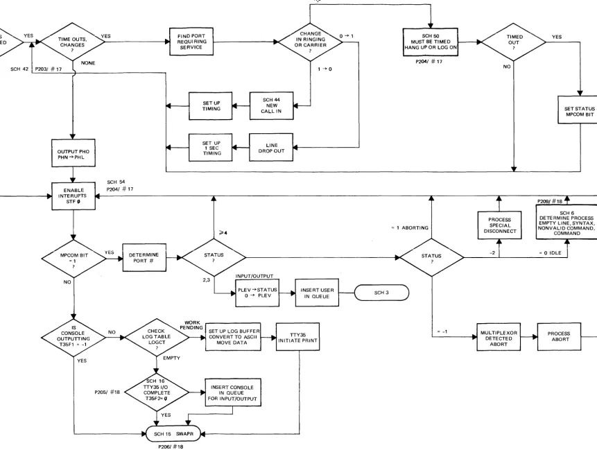
Figure 10 shows the main part of the scheduler. The phones coding is bypassed unless the phones command is used to indicate the hardware exists. The function is rather simple. It must connect the user on call up. It must time for log on within
the allowable time. It must detect and process a disconnect. When this is completed,
ClKIN T.B.G. INTERRUPTS
TSB INITIAL TIME SHARE
NO
SCHl
L - - - . . - t MAIN PART OF ~---I~
SCHIQ INPUT REQUEST
SCHEQ TASK COMPLETION
:f:!oUTC OUTPUT
SUSP DE--QUEUE
SCHEDULER
YES
SCH41 PHONE PROCESSING
SCH54
SET FLAG 0
INSURE SWAPPING UNDERWAY
SCH5
. - -... TTY PROCESSING
YES NO
SCH15 SWAPR
SET UP lOG BUFFER
SCH15 INITIATE EXECUTION
EXIT SCHEDULER
JUMP TO SCHEDULER
P201/#17
NO
CLOCI<~
l00M~~
UPDA~E
1/10 SEC
CNTR (DATIM +1)
RESFgT DATIM +1 COUNTER
RESTO:]
RETURN TO PROGRAM
The multiplexor communications is indicated by the word MPCOM. The corres-ponding user bit is set whenever servicing is required. The scheduler uses the user status to help determine what is required. A status of 2 or 3 is a return from I/O suspend. This establishes a new priority of 0 and the user is placed on the queue.
A status of 4 or more indicates that a command is being processed. RUN = 5,
LISt
=
6, PUNch=
7, etc. Refer to the command table P222/#18 for the sequence.A status of -1 is given when the multiplexor determines the user desires an abort. When the scheduler begins to process the abort it gives a status of 1. A status of 1 thus indicates an abort is underway and no further processing is required.
A status of zero indicates the user is in idle condition. This is the normal condition for receiving a new line of syntax or a command. The status of -2 indicates a special disconnect from the phones coding.
Once all of the multiplexor processing is completed, the scheduler then checks the console. When the console is finished, the scheduler continues with the SWAPR routine.
SCH 1
P203/ # 17
SCH 42 P203/ # 17
OUTPUT PHO PHN -+PHL
ENABLE INTERUPTS
STF '"
SCH 54
P2041 # 17
DETERMINE PORT #
FiND PORT REQUIRING SERVICE
SETUP TIMING
SET UP 1 SEC TIMING
SCH 44
NEW CALL IN
LINE DROP OUT
PLEV -+STATUS
L---401 0 --+ PLEV
NwO
1:
1--+0
INSERT USER IN QUEUE
SET UP LOG BUFFER CONVE RT TO ASCII
MOVE DATA
TTY35 INITIATE PRINT
P206/ #18
INSERT CONSOLE IN QUEUE FOR INPUT/OUTPUT
1
SCH 50 MUST BE TIMED HANG UP OR LOG ON
P2041 # 17
~ 1 ABORTING
SCH 3
~ -1
~
NO
PROCESS SPECIAL DISCONNECT
-2
MUL TIPLEXOR DETECTED
ABORT
YES
P209/ #18
SET STATUS MPCOM BIT
SCH 6 DETERMINE PROCESS EMPTY LINE. SYNTAX. NONVALID COMMAND.
COMMAND
~ 0 IDLE
[image:55.1229.314.1175.38.686.2]PROCESS ABORT