11
J-].
~I
~-I
I
~I
·1
I
I.
·1
I
I
J -~·11
I,
\1
I .
Progra:an·
ProcessiDIr···
...
']1
;1
~~
I
-J
I
-,]1
,~
I
'J
I
-'
JI
-;; I
..J
}I
-( I
,
..
'~
I
11
'1·1
. !,: I
,
" I
JProgralD.
Processing
.
LINK GROUP
F
il
i
r.
1
1
,
fI
fI
fI
fI
fI
ri
fi
fl
fl
tl
, II
,
II
:1
Prepared by
, Technical Publications Department, .
Link Group - Systems Division,
Binghamton, N. Y.
b;t
I R
;4;
A:¥
~
8)1
f
t:l
E td S
E
eOfi¥
1;; j
'an
8IR8Ult!n¥~
LP-1576-1
Copyright 1965
May 65
...
I'
1:
I
£tU~
oY'lItalHlfiMtJ
r
I
;.Figure No. Title Page
r
-,
I
1-1
General Purpose L'ogram Block'Diagram 21-2
Program Sheet. .
·
·
·
· · · · ·
3r
1-3
Coding and Constant Sheet· ·
·
· ·
·
·
4
I
1-4
Hollerith Card Code·
· ·
· · ·
·
6
1-5
General Purpose Program Card Format7
f"l
1-6
Drum Allocation Sheet8
I
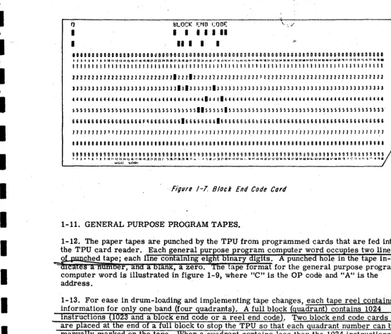
1-7
1-8
Block End Code Card. Tape To Be Run Sheet· ·
·
·
·
· · ·
·
·
·
·
· ·
·
·
10
9
1-9
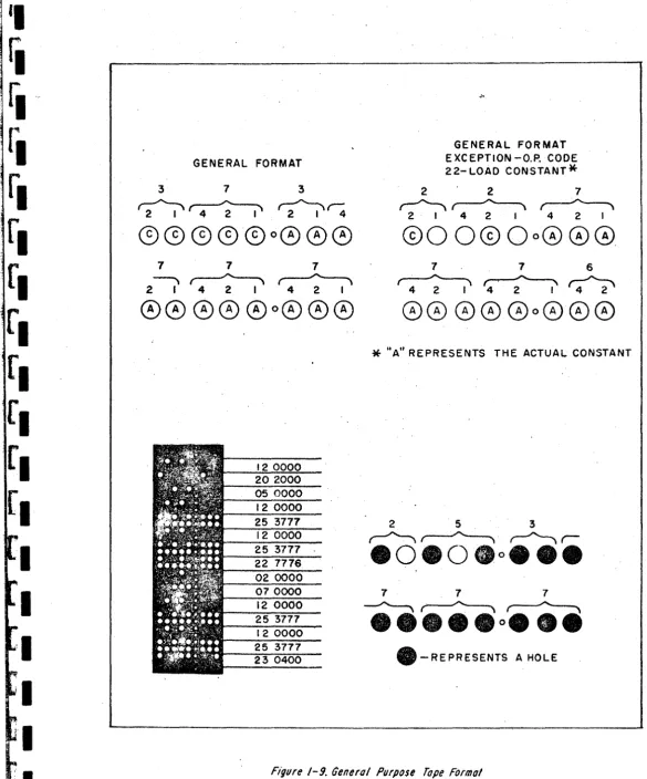
General Purpose Program Tape Format 11i
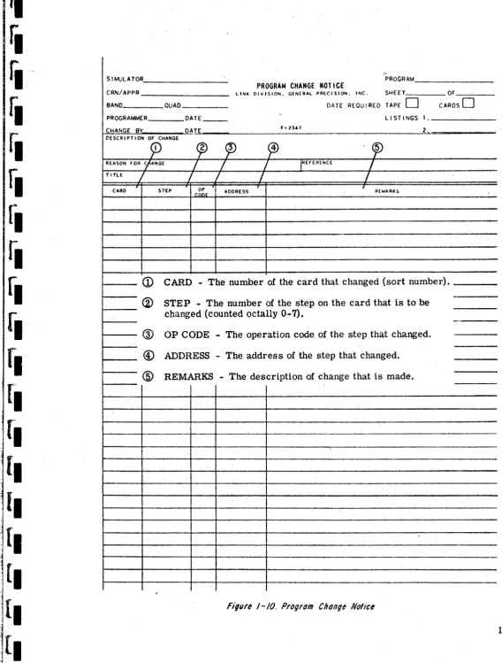
1-10
Program Change Notice· · ·
·
·
· ·
·
13
1-11
Drum Status Sheet .· · ·
· ·
·
·
14
1-12
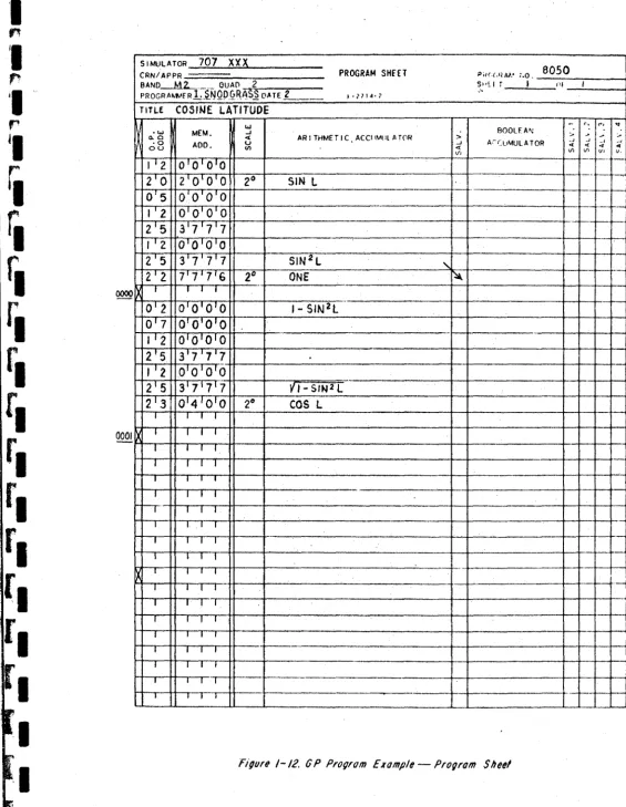
OP Program Example - Program Sheet15
I
1-13
OP Program Example - Program Cards.16
1-14
OP Program Example - Program Tape·
17
1-15
OP Program Example - Program Change Notice17
i
1-16
1-17
OP Program Example - Revised Cards Core Locations Sheet.' . ·
· ·
· ·
· ·
·
·
·
·
· ·
18
19
1-18
LFI Program Block Diagram·
· ·
·
·
·
·
20
1-19
Linear Function Interpolator Data Input Sheet.21
i
1-20
LFI Program Input Card Format·
23
1-21
LFI Program Output Card Format.·
26
1-22
LFI Program Tape Zoni-)s.· ·
·
·
· · · . · ·
28
i
1-23
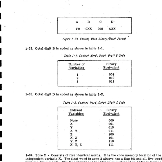
1-24
Control Word Tape Format . Control Word Binary/Octal Format· ·
·
· · ·
· ·
28
29
1-25
Address Instruction Word.· ·
· ·
30
1-26
Data Word. .
.
. · ·
·
· · · ·
·
30
fj
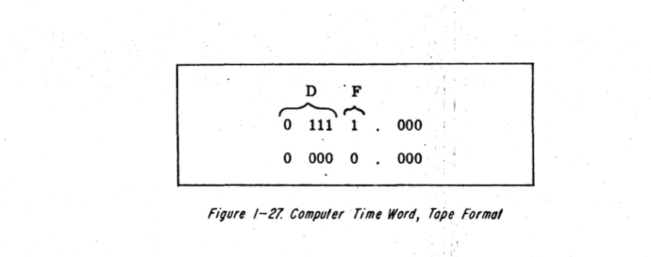
1-27
Computer Time Word, Tape Format.·
· · ·
·
31
1-28
LFI Program Example - LFI Data Input Sheet -32
1-29
LFI Program Example - Decimal Input Cards ,·
33
~.
1-30
LFI Program Example - Octal Output Cards.·
33
1-31
LFI Program Example - Punched Paper Tape·
·
34
I
1-32
DP Program (Initial Conditions) Block Diag,ram .35
•
1-33
1-34
Data Preselect Program Card Format. Initial Conditions Data Sheet·
·
·
·
·
·
·
·
36
38
q-35
Initial Conditions Conversion Example .· · · · .
·
·
39
1-36
Initial Conditions Punched Paper Tape .·
·
40
li
-37
DP Program (Radio Aids) Block Diagram.· ·
41
1-36
Radio Facility Data Sheet.·
·
·
· ·
·
·
·
42
1-39
Radio Aids Tape Codes.·
· · ·
45
li
1-40
1-41
DP Program Example - Radio Facility Data Sheet Radio Aids Tape Format·
· ·
· · ·
·
·
·
·
60
59
1-42
DP Program Example - Decimal Input Cards.·
61
1-43
DP Program Example - Octal Output Cards·
61
f,
1-44
DP Program Example - Punched Paper Tape.·
62
1-45
Data Preselect Change Notice.· · · ·
·
·
·
·
63
rill
,
r
J
-•
I
I
~I
I
Sectionj
I
j
I
'I
II
~
I
I
I
I
III
I
I
I
I
I
I
INTRODUCTION . . . .
PROGRAM PROCEDURES .
1-1. General . . . . .
1-3. General Purpose Program
1-5. Gener;11 Purpose Program Sheet and Coding and Constant Sheet . . . .
1-7. General Purpose Program Card . . . . 1-11. General Purpose Program Tapes . . . . 1-15. General Purpose Program Change Notice 1-18. Core Locations Sheet . . . . 1-20. Linear Function Interpolator (LFI) Program
1-22. Linear Function Interpolator Data Input Sheet 1-24. LFI Progr;im Cards . .
1-28. LFI Program Tape . . . . 1-43. LFI Program Change . . . 1-45. Data Preselect Program. . .
1-47. Initial Conditions Program. 1-49. Initial Conditions Data Sheet
1-51. Initial Conditions Card. . .
.'
.
1-53. Initial Conditions Tape. • . . . . . 1-57. Initial Conditions Program Change . . . . . 1-59. Radio Aids Program . . . • • . . • .
1-61. Radio Facility Data Sheet . . 1-63. Radio Aids Program Cards. . 1-117. Radi.o Aids Program Tape . . 1-121. Data Preselect Change Notice.
DATA PACKAGE
2-1. General . .
2~3. Program Cards.
2-5. Program Tapes . . 2-7. Program Listings.
APPENDDC . . . • . . . .
Program Processing Forms . . . . General Program Numbering System
LFI Card Program . . . . • . . . . Radio Preselector Type Code Words .. .
Page 1 1 1 1 1 5 9 12 12 12 12
22
27
31 31 3 31 37 37 37 37 37 45 58 58 65 65 65 65 65 A-I A-1 A-1 A-4 A-5Core Memory Charts . . . . Computer Mnemonic and Numeric Codes. Powers of 2 Table. . . . Octal - Decimal Integer Conversion Table. Octal - Decimal Fraction Conversion Table LFI Curve Example . • . . . • •
A-6
A-ll
. . . . A-12
. . A-13
• • • • • A-17
;os
II
,...
II
Ii
rl
rl
rl
fl
fl
fl
[I
[I
[I
I
I
I
Figure No. 2-1 2-2
2-3
2-4
2-5
2-6
2-7
2-8
2-9
2-10
Table No. 1-1 1-2 1-3
1-4
1-5
1-6
1-7 1-8 1-9
1-10
1-11
Title
Format for Numerical List of Equations . . . . . Format for Drum Order Loading of Equations. . . Format for General Program Bands 8-0P Listing. Format for Core-Memory Locations, Analog . . Format for Core-Memory Locations, Boolean . . Format for Linear Function Interpolator Listing Format for Data Preselector (Initial Conditions) Listing . . . . Format for Data Preselector (Radio Aids) Listing Format for General Program Bands Listing
(Absolute) . . . . . . .
Format for Loads and Stores Listing. . . .
Title
Control Word, Octal Digit B Code. . . . . Control Word, Octal Digit D Code. . . . . Input Card Frequency Versus Octal Output. Latitude, Longitude, and Frequency Field' . First Four Bits of Data Word D. . . . . Data Preselector Word Storage Locations Type Code 4 Frequency Bits 1 thru 9 . . Type Code 4 Frequency Bits 10 and 20. Call Letter Generation. . . . Type Code 5 Frequency Bits 10 and 20. Data Word D Type Code 5 . . . .
Page 67
68
69 70
71
72
73
74
75
76
29 29
. 47
48
51 53 53
54 55 . 55 56
I
I
I
I
I
I
The purpose of this manual is to describe the program processing procedures used i~
conjunction with the Mark I and Mark II digital computers. Section I contains descrip-tions of program procedures, while Section IT contains a description of the program data package supplied with each digital computer.
1-1. GENERAL.
1-3. GENERAL PURPOSE PROGRAM.
1-4. The GP program is composed of solutions to differential, algebraic, and Boolean
radio aids. Once the programmer has determined the program necessary to solve a particular problem, the solution is given an equation number and documented via a pro-gram data sheet. The propro-gram data sheet is then used as an input source document for punching GP program cards. The program cards are allocated to bands by quadrants, and placed in a card reader of a Tape Preparation Unit (TPU), which produces a punched paper tape. Finally, the tape is used to load the program on the desired drum band of the computer. The order of procedures required to process data representing the general purpose program is shown in figure 1-1.
1-5. GENERAL PURPOSE PROGRAM SHEET AND CODING AND CONSTANT SHEET.
1-6. The Program Sheet and the Coding and Constant Sheet are used to document the general purpose program. The programmer, after acquiring data for a specific aircraft or aerospace craft, forms equations for simulator purposes. When the programmer de-termines the equations, programs are formulated and placed on Program Sheets or Coding and Constant Sheets. The Program Sheet (figure 1-2) is used for eight instruc-tions per card, while the Coding and Constants Sheet (figure 1-3) is used for a single in-struction per card. The Coding and Constant Sheet is primarily used for diagnostic checks, using the remarks section as an aid in troubleshooting. The Program Sheet and the CodIng and Constant Sheet are the input sources for punching the eight instruction cards and the single instruction cards, respectively.
, _ .... , .... """, _ _ ' _ •• _ I I " ' _ ... _ _ , . _ . _ _ _ _ ... _ .... _."_,...o...i.I.._"_,,,,. __ ... ' ••• _ , , __ ..1... ,.1 II j .MI • W+ hli It • IIJ!i!u.,l'Ull1W I ! ! I I! 'leMjL'l 'J 1 1 'I " JJJlJUW,WUIU 111!~li .Jaw_III1L4· I' J' IIHI"I"'yNyU! •. _:J.~.!'" IIMYMN,'M'II'!JI !' !lJI!"!! -I"""
---N
PROGRAM SHEET
(FIGURE 1-2) ALLOCATE
AIRCRAFT OR CODING PUNCH
CARDS
DATA AND CARDS
TO BAND CONSTANT
SHEET (FIGURE 1-6)
(FIGURE 1-3) (FIGURE 1-5)
GENERAL NO PROGRAM
YES REWRITE PUNCH
WORK
PROGRAM CARDS
DECK (HOLD)
NO YES
MAKE
MAKE DATA
CHANGE VIA REPLACE PUNCH
PACKAGE;
PROGRAM PUNCH CHANGED TAPE
STORE CARDS
CARDS ON TPU
CHANGE
WORK .DECK NOTICE
(FIGURE 1-10)
YES
Figure I-/, General Purpose Program BlOCK Oiagram
I
I
I
I
I
I
I
I
I
I
I
I
I
I
I
/
l
/
/
l
,L
r-l
"T~
to
1
/ '
~
~~~~AP
R --~--' O~AD_-_t;-=~=~
PROGRAM SHEETPROG~l
SHrFT NO. or / \PROGR 'MfR DATE ,-?7t4·?
I
I
-\-TITLC/
1
j
/
I
I
II
®
®
N (')
.,
w BOOLEAN
·W MEM. -' > > > >
0..0 <{ ARITHMETIC ACCUMULATOR > -' ...J -' -'
· 0 ADD. u -' ACCULAUlATOR <{ <{ <{ <{
au Vl <( If). If) Vl Vl v.
t--I I I I
I I
-..
-I I I I
I I I I
.-I I I I
'
-r-<D
O.P. CODE-
Instruction number. Octal numbers only are used in this -,f- column. "
-Xr-
®
MEM. ADD. - Memory address of the instruction to be used or, in the -- case of a load constant instruction, the constant.-- -.
-®
SCALE - Scaling of the number in the Arithmetic accumulators. ,,-- Scaling is to powers of two only.--(1)
ARITHMETIC ACCUMULATOR - Description of the data currently COI1---
tained in the accumulator.-~
r-
-r-®
SALV. - Contents of the salvage register. The previous contents of-r
the accumulator when a load instruction is programmed.-X
-r-®
BOOLEAN ACCUMULATOR - Contents of the Boolean accumulator.f-
--r®
SALVo 1 - SALVo 4 - Contents of each of the four Boolean salvage-f- registers.
-I t
I I II I I I
I I I I
.--
-
...I I, I I
--I I I I
.,-I I I I
I I I I
-I I I I
IT'
I I I-
-I I I T ,,- ---
-IT'
I I I .. ,.I I I I
r-r-
-'-1 I"
Figure /-2. ProgrofTI Sheet
- - - -
. _ _ _ _ _ _ _ _ _ _ _ _ _ _ _ _ !""' _ _ _ _ _ _ _ _ _ _ .. ~· ... c .. :-~(j)
®
®
@®
®.
®
®
®
@)/
DATEr
/
I
I I
COOING "D CONSTANT SHEET I~
PROBLE'"
I
I
'-
M RK I COMPUTERPROGA~EA
I
/
1
I
/
1
JPAGE _ _ O' _ _ '
' .. 'Z, ... A \
-
..
..
..
II NSTRUCTI ON MilEMONIC
...
"EM....
ARITHMETIC .; BOOLEANCODE 1>.0 ADD. -' .. ACCu.lUL ATOR .; > > >
NUMBER OU · 0 c U ACCUMULATOR -'
'" -' -' -' -' REMARKS.
OJ en
'" c '" c
.,
'" '" VI
I 2 l • • • 7
..
~ll., , ,
1
<D
- INSTRUCTION NUMBER - Used to cOWlt the number of instructions.
in a particular program. Decimal numbers are used in this column •,
(?J - MNEMONIC CODE - Abbreviation for the instruction being used I
.
(Le., MUltiply instruction would be listed in the Mnemonic Code Column as MLT).G>
- O.P. CODE - Instruction number (MLT Instruction is 03). Octalnumbers only are used in this column.
(j) - MEM. ADD. - Memory address of the. instruction to be used. Octal
'1 numbers only are used in this column. 1
®
.
- SCALE - Scaling of the number in the Arithmetic accumulators • Scaling is to powers of two only:®
- ARITHMETIC ACCUMULATOR - The number actually being operated on. This number is in bin~ry format.CD
- SALV .. - Salvage register column. Stores the contents of the accumulator after a -load instruction.®
- BOOLEAN ACCUMULATOR - Serves the same purpose as theI 1 I
arithmetic accumulator. Used for Boolean instructions only .
. 1 ,
I CW - SALVo 1 - SALVo 4 - Boolean salvage registers. Serves the
same purpose as column 7. B.its may shift from one register to another.
@ - REMARKS - Used for brief explanation of instruction where
necessary. .
-I
1
I
I _
I
n
I
r
I
r .I
r'~
I
r
1-7. GENERAL PURPOSE PROGRAM CARD.
1-8. The IBM type 5081 punched paper cards contain the permanent program data. The standard Hollerith card coding 1s used. (See figure 1-4.) There are several card for-mats used for the general purpose program. The following is a list containing brief de-scription of each card:
a. Single Operation Card. The information punched on this card is taken from the
Coding and Constant Sheet. The single operation card (figure 1-5) contains: (1) equation number, (2) instruction number, (3) operation code and memory address, and (4) re-marks.
b. Eight Operation (8-0P) Card. This card is punched using the Program Sheet as the source of information. The eight-oper~tions card (figure 1-5) contains: (1) operation code and memory address (eight places) and (2) sort number. (This type of card is no longer used on the new Simulators.)
c. Eight Operations Plus Equation Number Card. The data required to punch this card is taken from the Program Sheet. The eight operations plus equation number card
(figure 1-5) contains: (1) operation code and memory address (eight places), (2) equation number, and (3) sort .number.
d. Program Title Card. The information required to punch this card is taken from the program sheet. (See figure 1-6.) The header card (figure 1-5) contains: (1)' equation' number, (2) band and quadrant number, (3) number of operations, (4) customer, (5) title of equation, (6) programmer's name, and (7) the date that the program was written.
e. Quadrant Header Card. The information required to punch this card is obtained from the drum allocation list. The quadrant header card (figure 1-5) contains: (1) band type,
(2) band number, (3) quadrant number, (4) band address, and (5) quadrant's first address.
Note
The quadrant header card is not punched until the equations are allocated on the Drum Allocation Sheet by the programmer. The program title card is updated after the bands on the drum have been assigned.
1-9. The GP program cards are punched and filed numerically in a work deck according to equation numbers. The cards will remain in numerical order by equation numbers until the equations are allocated to bands and quadrants (each band having four quad-rants).
1-10. The equations are allocated to bands by a programmer on a Drum Allocation
Sheet (figure 1-6). The Drum Allocation Sheet provides the initial information to arrange programs in drum order and to update the program title cards. When the eguations have been allocated to bands, the
a-op
cards are arranged in band and guadrant order in the work deck. The overall arrangement of the work deck is b band t e i.e. fast medi-um, and slow. Jac qua rant card group is follOWt'd by a card containing a block end code (figure 1-7). The cards are held in the work deck until a tape is requested to be punched. A Tape To Be Run Sheet (figure 1- 8) i;o used for requesting tapes to be punchedand maintaining a change record.
5
I
I
I
I
I
I
I
I
I
I
I
I
I
I
I
I
I
I
6
I
---r---.---.---.---..,
AJ.lCDJ::FG41.JKU1IiQPQRSTIJ'v'\'/XYZ 01234%789 ~+==(( » [ [ ] ]
IIIIIUIi .. 12 PUNCH
..
111111111 ~ II PUNCH II
II
..
\~
II
1111
oooooooooo.oooocoolllllilioolooooooooooooooooolloooooo01100001100000000000000000
11 I 4 ~, ' I i " lIunu IS"I1III,1fJltl1n14l':1"lJll;o9J{l)ll?1Ij.1 J~ It. ,'" IIf!1.;II· .. ·.,I\U.' .. "~'11'11U"'~S,,~')lU6e'I"''')~''''''fil''''''I'I'''1 f) " ' 5 " " ' . " .
I I I I I I I I I I I I I I I I I I I I I I I I I I I I I I I I I I I I I I I I I I I I I I I I I I I I I I I I I I I I I I I I I I I I 1 I I I I I I I I II i
212222222212222222122222222222122222222222222222'}222222222222222222222222222222 33133J33333133333331JJJ3JJ3JJ331J3JJ33JJJ3311J33JJ331131111133333333333333333333
44 4144 4 44 4 4414 4 4 4 44 414 4 44 4 4 4 4 4 4 414 4 4 4 4 44114 4 4 4114 II 4 44 4 4 4 C 4 4 44 C4 4 44114 4 4 4 4 4 4 444 4
55551555555551555555515555555555515555555555555555555555555555555555555555555555
666661666666661666 f ~ 6 616 6 6 6 6 6 6 6 6 6 616 6 6 6 6 6 6666666666666666666666666666666666666 6 ~
1111111111111111117711111171111117117 111111 111111111111111 11111 1111 J 11 I II I 1 11 J 11
888888818888888818888888188888888888188811611811811sl1811s11K8888881188~88888888
9 9 9 9 9 9 9 919 9 9 9 9 9 9 919 9 9 9 9 9 919 9 9 9 9 9 9 9 9 9 919 ~ 9 9 9 9 9 9 9 9 9 9 9 9 9 9 9 9 9 9 :1 g 9 9 ~ 9 9 9 9 ~ 9 9 9 9 9 9 9 9 9 9 9 9
t 2 l .. S , I , • '0 II I} IJ U IS ., :1 " wsc 'II ~ 11 ;z 1l 1. 'S " 11 :. :".I .\(1 II .1 I' I~ " ~ .• 1 ~. ;~ ~.~ t· I' ~. H I', ~~ ~I ~ .. ;. ,G)I \l ';1 >I ~ )(. \1 .... ,0 -.0 (,1 h. ,,1 1.4 co, " f.. hI"~ '0 " ': . > , /' 'b 1.111 l' IC
~o~a~' ________________________ ~ ________________________________ J
PUNCHED PUNCHED
CHARACTERS ROW CHARACTERS ROW
A 12-1 T 0-3
B 12-2 U 0-4
C 12-3 V 0-5
D 12-4 W 0-6
E 12-5 X 0-7
.F 12-6 y 0-8
G 12-7 Z 0-9
H 12-8
o
thru 9o
thru 9I 12-9 Plus Sign 4-8
J 11-1 Equal Sign 3-8
K 11-2 Left Parenthesis 0-4-8 L 11-3 Right Parenthesis 12-4-8
M 11-4 Left Bracket 11-3-8
N 11-5 Right Bracket 0-3-8
0 11-6 Decimal Point 12-3-8
P 11-7 Division Sign 0-1
Q 11-8 Minus Sign 11
R 11-9 Asterisk 11-4-8
S 0-2 Ampersand or Plus Sign 12
_ ... "mIWTr.VIII_Il_""PWII'i,,'.n"_r!l_TlY'p"='. r,n,. _ _ _ ' _ - ' _ _ _ , . . . . rlt:M4 . . . . _ _ If 4 p,[ [, 'd [,"I fl.'" ['!.I.!Ii!';.,[.!'~ j.!U,._[,!IIl'J ,'JeMiWlUy;! I ,1.11'[':",lhJI,[MlI!! I, JW" W!tijb!49!1J' IIlp,UWW'61I! l'!!JMW
-APPlICATION ~ GENERAL PURPOSE PROGRAM
lIiM 1401. 1410. 1440. AND 1460 DATA PROCESSING SYSTEMS
STORAGE LAYOUT
UAlt
I SYMIOllC
I OPERATION
.
I~~~::~'~~ r.~~sH
I
II REMARKS J PRIM.&RILV USED FORDATA _8£A III . , 4DDRESS A
r
-IDIAGNOSTIC PR06UAMS
PER CARD lOCArlON
..
.
" o , ." 'x ',t lO
"
'",'..
-..;r 'M '.,.'..
•
'",',
WO.O ... K , , L t ' I , , , , , •
I SYMBOLIC 0 -. I 2 3
..
5 6 7. 8 OPERATIONS OArA
r~~MOR~I~
ADOtISS SPACE 3lH~~f_~I~ 3;~t~I~E~I~
l ADDA£SS SI'ftC! t AIlDRISS SJIW 3IN~~~~~:(fl!l~MOAY~
' 0 "DORI·.U ADD~m SIIAC( J~MlM~Y$I!
& ADOfIES$ SI'IICI' , 31~'~I~£NOR~li
ADDRfS$ SPACI & CCO! AIlORlSS l:IJ&lcO~I~MO~IISOR:~
I;UtoI8!PER CARD lOCATION •
,.
" 'x ·,t lO
"
.. ..
l:2 ·U I!! I' 'a I..
U !II ' jWC.O ... K
I SYMBOlIC 0 I 2 3
..
5 (, 78 OPERATIONS
I&~:MORV;
,.
~IL~~:IIO~~~I'~I~IIO~~~
ID4o:r
WOA:\.
~H:J~MOR:~ ~[f:::MOA:~ ~0:JWEMOR~~ ~1<OP ~I~EMOR:I. i~~T~I,
SORI~I
PER CARD PLUS OA'A
&
ODRf~ .. ~ L ADDRESS ~ 1 ADOR£SS ~ & eoo ADDRUSN!
!. C ADOR£SS ~ I t ADoms ~ L co ADDRESS ~ & tllOE ADDRESS .. ~ UMBER NUMBIREQUATION NUMBER W lOCATION .O .... RK 0 ','
-
,.
" 'x ',/ 30"
'".
,
'611,
',0' ~,' 'to 'n' '..,'....
I SYMBOlIC , f;M, S." ZERO MUST
8E
III COL_ 21 TO HAVE UPOATING WORKPROGRAM OA''''
~~::1
" SPACES 8 4N:/-I
0 NO •• OF .. CUSlOMER ~ '"3
TillEi
PROGUMMERi
DArE Of PROGRAM J1
IISER QII4D OP5.
'"
..
TITLE CARD lOCATION
•
,
',.
'n'"
30"
'"..
'''; ',,' '611 'M 'l': ~,' 'to....
'..,'....
wOio .... AK
I SYMBOlIC I BAND I IBAIIO NO.1 IE--COS TOMER - - - ; . j IQUAD NO. I i A&~~~$S I * NECESSARY FOA UPOA TI~G PROGRAM
QUADRANT OA'A
I
fAST MEDIIIN I100[,
THflEf, TWO,I I I I I
Ig:AO
I
IONEtTWO" TNR E,I I I
t~D'\I~:~gl FI.,T J.400.SLOW fOUR
.
fOlIA.
'OORES' • -000,!'lEADER CARD lOCATION 0 ',.
" '2d .. t 30
"
..
" '.,I'"
,
"0' ',,' •••
....
•
W MARK , , I • I • ! , , • , • f I....&.-.L...L-I , 1 I , , • • • , • , ! • I · ' I ! • , I ! ! , I I ' I ! , , ! '....&.-.J..-' I , , , ! , • I I • , I • , •
I SYMBOlIC
I .I[OUA'~I
~~I ~1
$KUCH HUNIfR
I
I.
'o~:rFOR eN US TtN6S AIID DATA
ANALOG CORE OArA
I R£M~RI<S '1_""1£11 lOCAl PRotHS'Mr. MAc..nlt TAPE)
MEMORY CARD lOCATION 0 -
','
"0' I 2,.
"
'"
TVI''"
-.;:,: W ,,,{,
• 0 ',,'....
' •W .O .... RK . , ' ! , I " •
I SYMBOlIC
BOOLEAN CORE OA'A l r REMARKS JfQUA~~ 'INUIltfR -181~ SKETCH NUIIIIER
1
II14IN /: WORD SPW: LOUT. PIIO(£S$'NG MAGNEIIC TAPE$ J :lJI CO~~ fOR ell liSTINGS AND DATAMEMORY CARD IOCAnON 0
',.
"
,
30"
" ~ Tul TAl 1'01 '10 'I!' 9Q ~-y-rW .0 MA.K ! . ' • • , ' I ' , ! ' 1 1
I SYMBOlIC
.
OArA
lOCAnON
•
',.
• '2d '2~ lO l!..
" '''; '611 'M ~o' eo
....
.
...
',,'
W R MARK ! ' ! ' I '..1...L...
I-~l--I-
SYMBOlIC ..
..
~g;;~K<::
:
:J::::
:~:
::
:'~::::"!::: ~~:::
::: ::
:s! :: : :"':: :: :": : : :
:~
:::
:J~
::
::~:
::
:.~:
::
?a:: ::
7~:::
:: : : :
!~:
::
~:::
:":: :
L I
~:'I.;
; ; ; ;'; ; ;
;;'! ; ; ;
;'~
; ; ;
~
; ; :
:0: : : :
~
; : :
~!
: ; ; :;;; ; ;; ": : : :
:0: ; : ; :-; : : : :"' : ::
.~ :~:
! : : :
~
: : :
~
: : : :.. ' : : :"' ; ; :
;n: : :
. Fi,UfI /-5, 6101(0/ PUfPfJ$I PffJ9fOlfl CfJfd FOfllolI
I
r.uu
,---I
rOUATION NUM8ER NO. STEPS or sua- TOTAL DRUM LOCA TlO·N OF FIRST STEP ENGR.II
I
I
1
-I
ff
-I
---
1---I
I
I
I
-I
I
I
I
DRUM ALLOCATIONCUSTOMER/~IMULATOR BAND QUADRANT
I
I
Figllre /-6. Orllm A//ocolion Sheet8
II
f.
f.
f.
f.
f.
f.
r.
t.
(.
I
'I
I
I
I
f)
I
I
~LOCK I I
.. I
F.:~to GODI=.:
• • • II
•
•
.IOOOOOOOOOOOOOOOOOODdOOOOOOOOOOOOOOOOOOOOOOOOOOOOOOOO00000000000000000008000000
, , I • , • , • ~ II It 1111 .f ,\ 'i Il ' .. It 11" U lJ I. 3 Ill' n 11» )1 )1ll Jot.to, l6 J' 11 1!6 _0 41 4: 4J u ') (6 ,I " "'jQ!tl U ~)t» l 6 ) ' ) 1 ) ' " ' ' ,t u ... " ... u ... " 11 I, JJ ,. I) I, n II " .
'" 1'1111111111111111111111111111 t 11111111111111111111111111111111111111111111"
IIZZZZZZ2222222222222ZZ222'222822222}22222222222'222222222222Z22222Z222222222222 J l l l l l 1 3 3 3 3 3 3 3 3 1 3 3 3 33 1 3 3 3 J 3838 J J 3 3 J 31 J 3 J 3 3 3 3 3 J 3 3 J J 3 3 J 3 3 3 3 13 3 1 3 3 1 3 3 1 3 3 3 3 3 J 1 3 3 3 l H
• •••• 44.4.444.44.4.4 ••• 4 •••• 4.444.1444.44.44444444444~444 •• 444444444444444444444
S~~55S55~55555~5555555555555555511555S5.5S5555555S555555555555555555555555555555
6&&6&6"'666666666F~66666666'66666666'666666666b6666666666666666666666666656661'
7 71171711111111111111111//177//1" 11/711711117,1111111111111111/111/1/11111/1/11,1
8 I 8 8 8 8 a I 8 8 8 B 8 8 8 8 8 8 8 8 8 8 8 88 8 8 B 8 d 8 8 8 8 8 8 a 8 8 8 8 8 8 8 8 8 8 8 8 8 8 8 8 8 8 8 8 8 8 8 H 8 8 • 8 8 8 8 8 8 8 8 8 8 8 8 8 8 8 8
999999999999999999999999999999999999999~999999999999999999~~99~9999~999999999999
[image:15.616.17.573.50.525.2]I I J • , , , • , 10 !lUll It')I' I' '11'.'011 ::n:. 'S 151Jlt:t \0 11 II " ., '!llf;I:, J"~u 11tH'!' ~,It ~a H'AI!JI '11U~!J!J'J6 !J')I')IHO"6j uu,~",t .. ,~ '.:1 ':!I '.,~" ,. l' I t . tjGC ~OBI
Figure /-1. Block End Code Card
1-11. GENERAL PURPOSE PROGRAM TAPES.
1-12. The paper tapes are punched by the TPU from programmed cards that are fed into the TPU card reader. Each general purpose program computer word occupies two lines o ched tape; each line containing eight binary dIgits.
A
punched hole in the tapein-er, an a an, a zero. e ape orma for the general purpose program computer word is illustrated in figure 1-9, where "C" is the OP code and "A" is the address.
1-13. For ease in drum-loading and implementing tape changes, each tape reel contains information for only one band (four quadrants. A full block uadrant contains 1024
ns ruc IOns and a bock end code or a reel end code). Two block end code cards are placed at the end of a full block to stop __ t~!Lf~U ~2...!!!.ili~s..~~,::!r'!.rr.t...!!umber .£'~l) be manually marked on the tape. When a quadrant contai_~~_J~§§...th!!!}" the_!021JJ}§.tD!£..llgnsl-_ (short block) only oneblock end code cardfs-n-~e'ded to s.i~p_.!E~ tape in the TPU. ..9..~ad
rants are norman}:,: short blocked so that.J2,rograms c~.!l.l>_€Lf!han~d with9ut having to move entire programs from one quadrant to another. A reel end code is punched at the end of each tape. The-reel end cOde is used during a drum loading oper~tionl and ends_ the transier of data from the computer tape r'e~he computer. _When all the data to
e s ore on a par ICU ar rurn:t5arid quadrant is loaded into the computer (it is.stored in. core-memory, e a a IS en rans erre 0 the selected drum-band quadrant. After complehon of the drum loadmg, me data in core-memory is checked against the data on the applIcable drum band quadrant. This aIIoWs-ThefiiformatlOn-on'the drum to be
cheCked atter eac~ quadrant IS loaded. --.---,"---.
1-14. The programmer's name, the date the tape was punched, the operator who punched the tape, the time the tape was punched, the simulator designation, and the band and quadrant number are written at the beginning of each tape reel. After the tape for the first quadrant is punched, the number of the next quadrant is manually written on the tape. This procedure' is also used on the second, third, and fourth quadrants.
J .
!I
"
~ ~
,,\
"!llIIJj' '1"', I mMMl1 III ',,"1'''' '[',.!IIII'IJ!I'!II .... Il[;·mIT"n.'."". '"nI·,llr!' • • '''wrulllU·,,,.,_-I!bunl''',,,,. _ _ ' . . . prn,,,tm.' _ _ _ .''Pll'nnm.' . . . _ _ _ . . . ., I ,'I,,!J,' 'I" ".,IIWI,w..I!,il 'IIIM.II!'1 'jUtM!LJ".! IUIWUhlWlW"IJiktl 'U,J,Ll:ijlWd!'
---....
o
.
BAND
I
QUAD TNR REQUESTED BY
!
TAPES TO BE RUN
TIME 8 DATE REQUIRED BY TAPE PREPBY REMARKS , ,
I
I I
I
i
"
I
I
.
I
: ' . ~>"~ - - - - . . .
.. -., .. .'.,---~
'I
f. I
Ii
fl
fl
fl
fl
f l
[I
rl
fl
[I
I
I
II
'I
I
~.;
I
~I
GENERAL FORMAT
3 7 3
~~~'4
000(0)0000
GENERAL FORMAT E XC EPTION -O.P. CODE 22-LOAD CONSTANT*
2 2 7
~~~
2 1 4 2 1 4 2 I
00000
0000.
7 7 6
~~~
00000
0000
*
"A" REPRESENTS THE ACTUAL CONSTANT7 7 7 . . . 0 • • •
e
-REPRESENTS A HOLEFigure 1-9. General Purpose Tape Formal
[image:17.616.0.586.21.725.2]I
-,I
l
I
I
I
I
I
I
I
I
I
I
I
I
"I
I
oc::I
I
I
1-15. GENERAL PURPOSE PROGRAM CHANGE NOTICE.
1-16. A major Change in a program may require that the program be rewritten, while a minor change is recorded on a Program Change Notice (figure 1-10). For minor
changes, new cards are punched from the information recorded on the change notice; then, the old cards are replaced in the work deck by the changed cards. A new tape will be punched from the revised work deck. After the tape' is punched, the quadrant that was
changed is annotated by underlining the previously written quadrant number. Quadrants that are not changed are loaded in the computer in the check mode to provide a running check of the TPU and the drum loader. Each time a tape is loaded on the drum, a Drum Status Sheet (figure 1-11) is also updated.
1-17. A sample general purpose program is shown as follows: Figure 1-12 illustrates the Program Sheet; figure 1-13 illustrates the punched program cards; figure 1-14 illus-trates the punched tape; figure 1-15 illusillus-trates the Program Change Notice; and figure
1-16 illustrates the changed program cards.
1-18. CORE LOCATIONS SHEET.
-1.:19. The Core Locations Sheet (figure 1-17) is filled out the time the general program 1s written, ~d the c9re locayon !tssignment!.~:r:e _~!~e.
,All
mathem~hs..~Lqu~_t-:lt_l_e_s....-__ needed in the simulator program (with the e~~..£2!!.sta:.nt~~h!£~~_ .. !?~Epred 01]_the drum) are stored in core memory .. Th,~,Jnath~matical_m!.l:!nt!ti~,§'.,;~£~Las§l.g,!l~e,,-·-_ _ _ ciUc core addresses on the Core Locations Sheet. After core addresses have been
assigned (analog and Boolean addresses) , analog and Boolean cards are punched from the data on these sheets. These cards are punched using the format in figure 1-5. A mag-netic tape i:; prepared from the cards and used in making a detailed program listing, which willlJe explained in the Data Processing Section II.
1-20. LINEAR FUNCTION INTERPOLATOR (LF1) PROGRAM.
W&CZJU!.
1-21. Characteristics of flight equations ar", placed on Linear Function Interpolator Data Input Sheets that are used to document the
LFI
Program. Then, cards are p"Urichea"uslng a decimal card format that must be converted roan octal card format prior to the gen-eration of a paper tape. Conversion from a decimal-to-octal format is accomplishe.d through the use of an IBM 1401 cO?lputer! containi~~~.E.~~iaI~e~imal:!.0-_9ctal conver-:-sion program. The resultant cards are used to produce the punched paper-tape, which is then loaded onto the selected interpolator drum band. A block diagram of the LFI program procedures is shown in figure 1-18.1-22. LINEAR FUNCTION INTERPOLATOR DATA INPUT SHEET.
1-23. The Linear Function Interpolator Data Input Sheet (figure 1-19) contains the data needed to punch LFI input cards. This sheet is divided into two sections. The first section contains information concerning the number of variables.1 whether or not the varIables are indexed, scaling of the variables, etc. The second section contains the values of the breakpoints, as taken from the -L'FfcUrves.
·f
""---''"
12
'I
r.
r.
f.
f.
f.
f.
f.
f.
f.
f.
f.
('.
[I
II
II
[I
[I
[I
,t ...
SIMULATOR PROGRAM
PROGRAM CHANGE NOTICE
CRN/APPR LINK DIVISION. GENERAL PRECISION. INC. SHEET or
BAND OUAD DATE REOUIRED TAPE
c=J
CARDS0
PROGRAMMER DATE _ _ LISTINGS I.
CHANGE BY DATE F· 23.7 2,
~ESCRIPTION O~HANGE
cp
~
CJ>
.~REASON FOR '7'ANGE
/
/
/
IREFERENCE7
T ITL£ / I /
/
1
CARD STEP r~~r ADDRESS T REMARKS
CD
CARD - The number of the card that changed (sort number).<ID
STEP - The number of the step on the card that is to be changed (counted octally 0-7).-®
OP CODE - The operation code of the step that changed.<i>
ADDRESS - The address of the step that changed.@
REMARKS - The description of change that is made.Figure /-/0. Program Change No/ice
[image:19.611.0.569.22.772.2]I
I
I
I
I
I
I
I
I
I
I
I
I
I
I
I
I
I
I
F
MI
M2
M3
SI
S2
S3
S4
14
-.
DRUM STATUS
000 001
-002 003 010 01 I 012 013
-, 020
021 022 023 030 031
1---032 033 040
~-041
042
-043 050
051
052
053 060 061 062
063 070
071
072
-073
-.
SIMULATOR 707 X)(~
CRN/APPR PROGRAM SHHT PiU.(.qA' .. :~o. 8050
BAND~ 0UAO 2 s.·t I r I "~I
,
PROGRA"VfR l~~~OP(}RASS (lATE 2 I ·n",? .;'"
TITLE COSIt.JE LATITUDE
....
..
r •...
"
...
MEM. .J BOOLfA" ::- ~0..0 « AR I THMf TIC. ACC11Mlfl A T(lR > ...
::-· 0 ADD. u ..J A:-r:UMUlATOR .J J -I -"
OU I,/) «
.. ..
of..
VI III III VI v.
IT2
0'0' 0'0
-2'0 2' OTOTO
2°
SIN L . - . -~o
5o
0 0
10
I ' 2
0'0'0'0
-2'5 3'7 '7'7
I 12
0'0'0'0
.-.,--.
2' 5
3
17'7'7
SIN2L
,
2'2
7'717 '6 2°ONE
~I I I I
..
0'2
0'0'0'0
I-SIN2l0'7 0'0'0'0
IT2
0'0'0'0
..2'5
3'7'7
17
, '2 0'0'0'0
2'5
3'7'7
1]VI-
SIN2L-2'3
0'4
TO
TO
ZC'cos
LI r T T
000 I
,
I,
,
II , r
,
I r T,
, T TI
,
,
,
-.
, I I,
,
, I.-r T T
,
,
I T T~ T t I t ..
r r T T .- '-i
T T T
,
, ,
I,
r T T T
T
,
, ,
f--r T T T
T
,
,
,
,
, I r-Figure /-/2. (j P Progrum E umple - Program S heel
[image:21.617.4.570.26.756.2]I
I
I
I
I
I
I
I
I
I
I
I
I
I
I
I
I
I
I
---._.
-------.--"1~~-f)1,) 7'17X'<'>( (;1),)1"it:: ,-:nITIJT)~ I.
I I I I I II II
I I I I I
)'ion W'4'i'i
.. I
.. I
OIOIO~OOOOOODOOODOODOOOOIOODOIDIIIOOOIOOOOOOIOIIOOOOOOloo~ooollooooooooooooooooo
• 1 J • , • I • t .1 II IJ IJ II I:' n. " It ,,:O}I 11111& 1) 16 II ~f.~ JO 11 t ' 01 •• , .t,' WI 1'1 to u " 41 U I', tl." 4, 4'1 '10 ',I ',: 'sl ~ ")~ '.to 'I' 'If" ~ ,. , .. U ~" " ' . , ... ~ 10/1 ' .. d It 1') " 1/
I. " ..
11111111111111111111111111111111 I 111 I II 111111 I 1111 I I 11 II I 111111111 I I I 111111111 II
2 2 2 2 22 2 2 2 2 2 22 1 2 22 2 12 212 12 2 2 12 2 2 22 2 2 2 212 22 2 2 2 2 2 2 22 2 2 12 212 12 22 21121212 2 21 2 2 2 2 2 12 2 2
Jl 3 3 3 3 33 J 3 13 3 J 31 J 3 3 31 J 13 3 J J 33 3 J 3 J 3 J 13 3 3 J 3 J 131 J I J3 3 3 313 3 J 3 3 J 3 33 J 3 3 I J 3 13 13 13 3 J 3 3 3 3
44444444444444444444144444444444444444444444444114444444414444444444441444444444
5 Sis S 5 ~ S S ~ S S 5 5 S 5 S S 5 5 S S S 5 ~ 5 ISS 5 5 5 S 5 5 5 5 5 5 II 5 5 5 5 5 5 5 5 I 5 5 5 5 5 IS 5 5 5 5 5 5 5 5 5 5 5 5 5 5 5 5 5 5 5 5 5 5 5
6666666666666666~6666666666666666666166666666666666666661666666666666166666666,6
IIIII1 II J J " " J J II 1 J J 11111 I J 111111' J J ) ) J , , J J 11 I I 1 I , 1 I II I I 111 I II I I II I I J I III , , I I I I 18888888888888888888888888888888888888888888888888881888888888888188888888888888
999g9999~99~999999999999999999999999~919999991999991999999~199999991999999999999 11 J . \ , I , • • 0 I 1.11""",11 II 1':O}I:,','J:4!,_-"U.1JtJOJII: ,. i"JJ 10,. II" '1401t.'.J".:'''CI''~,,·..o''I'.:·II''''''t·'''' ;". __ 1,,110110""1&41;.',,,,,,,,,'1 '011 '."1/41\" II ' " , .
-L-_ _ _ _ _ _ _ _ _ _ _ _ _ _ _ _ _ _ _ _ _ _ _ _ _ _ _ _ _ _ _ _ _ _ _ _ _ _ _ _ _ _ _ _
16
\;')'50,)00
I
\251777 '120000
I I
~?'51777
I
\2~777';
I
000111100001011100010111100000111100000000000000111100OOOOOOOhOOOOOODOOOOIOlllII
t J J 4 ) , r I , I' II 111l 14 I~ Ii II I' I, 1'0 11 n 1;' " l~ 3 11 It 19 lO 11 1: jJ j4 I'. Iii 11 11 '1 ~U 41 4.' "I U 4', .. H . . . , 'JO \1 ':1/ ')J ~ )) ~ )1 )I ,,.,Ujl .} 101 \4 ~ " ., .. ~t 10 /I 11 IJ 14 n ,. " J. ".
111111 III 111111 I 11111 I 11111111111 11 I I I III I II 111111 I I I I II I 11111 111 II 11111 I , I II , II
22122222221212222222222222222122222221222222222122222221222222221122222222222222
331) 333313 3333 J 33333 J lll3 3 3 3 3 3 J 333 3 J J 3 J I J 3 J 333 3 3 3 3 J 3 3 333 J 133 J J J J J 33 J 3] 3 3 3 3 333 3 J 3
4444444444444444444444444444444444444444444444444'444444444444444444444444444444
5555555SS555S5555555155555SS5S5SS5S5Ss15555555555555SS55155555555555555555155555
66666666666666665666666666666666666666666666666666666666666666666666616666666666
11111111111 II 1111111111111111111 , 1111 , , 1111' 1 I I II , III I , 11 I 111'1 II 11111 I 111111 1 I 1
888888888888888888888888888888888888888888888888888888 8 8 8 8 8 888888888888818888888
99999999999~999999999999999999999999~999999999999999999999~999999999999999999999
I 1 ) • ') , , t •• 0 t 'I I) It ''I " If I ' 't:o l' 111):4 ... 110 tr lilt JO JI J.' J~.M 11.)1, )1 .II ",4')4.1 4" 4j U t)"""":.o ',I ':1/)1'" ')))6 ':II '.Ia1','1 110 , . , : 'oj ~~ n " , \1 .... ' '" " ,! IJ •• I) ~ tI ." " _
tt~'- ~oal
\1)201)(11)
1
\ t 2iJI')Ij:)
I
\~'B777
I
~ 12')1)1)1)
1
~~'5'3777 I
01011110001011110000011110000000000000011110000000000000010110000000000001011110
, 1 ) • S • , • t It II 11 U .4 IS " 11 I' 1, 10 ,I n 1:' J4 n 1111 ]l1t JI) Jill JJ )4 J<I '" J1 :II .1'1 '11 u t,' 4j U 4', " ., .. . , !lei )1 )1 ')J ')I ~) "J6 \1 ~ )' 6.0 " Ll LJ ... n " " .. ,' to It " I} ,. 11 " " ,. " I)
111111111111111111111111111111111 II 1111I III I I 1111111 I II1I 11111111 111111111 I1I1 II
22122222222222222222122222221222222222122222221222222221222222222222222222222222
3 l 3 J3 J 3 3 3 3 3 3 3 3 J3 3 3 3 3 3 3 3 3 3 3 3 3 3 313 3 3 3 3 J3 3 3 J 1 3 3 33 3 313 1 3 3 3 3 J 13 3 3 J3 3J J 3 J 3 3 J 3 3 J3 3 1 3 11 1 44 4 4 4 4 4 4 4 4 4 4 4 4 4 4 4 4 4 4 4 4 4 4 4 4 4 4 4 4 4 4 4 4 4 4 4 4 4 4 4 4 4 4 4 4 44 4 4 4 4 4 4 4 4 4 414 4 4 4 4 4 44 44 4 4 4 44 4 4 4 4 4 4
SS 5S ~ 5 ~ 5 5 5 ~ S ~ 5 ~ ~ ~ 5 S 5 5 5 5 B 5 5 S 5. S 5 5 5 S 5 ~ 5 S ~ 5 S 5 5 5 5 51 S 5 5 S S 5 5 5 5 5 5 S 5 S 5 S ~ 5 S 5 5 S 5 5 ~ s I 5 5 S S 5
6666666666666666~666666666666666666666666666666666666666666666666666666666666666
J 1 I J I J I J 1 J '11 j I 1 I J , 7 I I I I 1 1 I I I I 11II1 1 I 1 I , I I 1 I I I I , '1111 , I 1 1 I I , , 1 1 1 I , , I 1 I I I I 1 I 7 , 1 1 1
.88888888.888888888888888888888888888888888888888888 8 8 8 8 8 8 8 888888888888818888888
9 9 99 9 9 9 9 ~ 9 9 ~ 9 9 9 9 9 9 9 9 9 9 9 9 9 9 9 9 9 9 9 9 9 9 9 ~ : 9 9 9 9 9 9 9 9 9 9 9 9 9 9 9 9 9 9 9 9 9 ~ 9 9 9 9 9 9 9 9 9 9 9 9 9 9 9 9 9 9 9 9 9
' ) ) . \ . ' , . ,'I 1:'lltl'JI'IIIII'lGl':::J:',.K1':'"lOilJ/liJtJIJt. 'II ,',';It,.,'t, II ',tt,I' 'jl,·,.l,,·," . . • \.j .... ' .·~w~· .. · .. IUI .... " .. "''011111),.,·,' .. ·1 " .. ea
[image:22.616.12.571.36.770.2]u~ ... t.. ~OUI •
'I
r.
fl
fl
rl
fl
cfl
rl
fl
fl
(I
(I
tl
(I
II
(I
II
1.1
II
Figure /- 14. G P Progr(Jm EX(Jmp/e -- Progr(Jm T(Jpe
SItv'ULATOR 707 XXx. PROGRAtv'
CRN/APPR LINK 01.1 PROGRAM CHANGE NOTICE SION. GENERAL PR((ISION. I>;C. SHEET
BAND
M2
OUAO 2 DATE REOUIRED TAPf0
PQOGRAMMERSNODGRASSOATE4-1-64 LISTINGS
CHA.'\GE ByJ· WEB5LY DATE 4-1-64 F·2347
rESCRIPTION OF CHANGE
CHAtJGED ADDRESS
REAS?~2tO~s'tD~~EOTHER CALC. - WRONG ADDRESS IRI.F£RlNC~
T I Tl£ COSI/JE LATITUDE
CARD STEP or I A(lDRES~ R,"ARKS
""n'
DeoO
6 25 3777 REF0000 SA 23 2002 ADDED STEP
:0000 7 22 3776
REF
!
COOl 6
23
D404 wa.s 23 0400i I
I
IFigJ;e /-/5. GP hogr(Jm E.romple - Progr(Jm Ch(Jnge Nolie,
8e50
I OF I
CARDS
0
,
.2 I
"
[image:23.616.0.584.25.728.2]I
I
I
I
I
I
I
I
I
I
I
I
I
I
I
18I
"31)'5')
"\. t ~Of)Of)
•
"'ll~11)1)1)
I
\ ~()~I)')i)
•
1'12}-O\'; 7J')7lf><'<
1 1
~f)'5I)'})f)
•
~~ t ~!)I)')I)
1
~1~1)1)(})
•
~"~'5'3777 I
CI)~t"iE
un
I TIJOC: I • 1 1 11 1 1
~~'53777
•
\,1 ~1)1)1)f)
I
1 1 II II
\,1 ~f)l)')1)
•
'5;~fl)O(iRq<)<) 2.29.*>,.
II 1 - ' 1 1
II 1
\~'H7?7 ~~~~1,)~ '3') ') 1').) I)'})
•
•
.IOIIIIOOOIOIIIIOOOOOIIIIOOOOOOOOOOO~OOIIIIOOOOOOOOOOO00010100000000000001011110
1 J J 4 , • J • , 10 II tl1l1~ Ii 'I IJ I' 1120 11221)24 r.t Jln 2119 JO II )1 JJ)of l!l" J111 lHO.1 41 U U 4:!1.' 41 ••• ,)1) ')1 )] 1)!r')!1 ~)I :. ),.0 '''1 iJ ~ 0 " I ' " ' ' 11 " n JJ '4 1) Ji " 11 It I)
" 1 ' '11111111111111111111111111111111111111111 II t 1111111111 11111 1111111 I 11111111
22122222222222222222122222221222222222122222221222222221222222222222222222222222
33333333333333333333333333333313333333333333333313333333133333333333333333333331 4444444444444444444444444444444444444444444444444444444444B414444444444444444444
55555555555555555555555555555155555555555555555155555555555555555555555555155551
666 '," 6 6 6 6 6 6 6 6 6 6 fi 6 6 6 6 6 6 6 6 6666666666666666666666666666666666666666666666666' 6 6 6 6'
111 J 111 J J J 111111 J 111111 J J 1111 J 1111 J J J J 1 J J J 11 7 17 11111 J J 1 J 1 17111 J 1 J 7 1 J 7 7 1 J 11 J J 111 J
8.8888888818888888888888888888888888888888888888888888888888 ••• 888.88 •••
1.88 ••••
'99999'999'999999999999199999'999999~999999999999999999999~99999999999999'999999 , 1 ) • 50 , , , , to ,: 11 IJ I. I) 'I If I, 1"10 If 111) ,. ~ ~ JJ 1111 .10 11 31 JJ )t b . Jr lilt 40 4' I" U U • .., " " ""oJ:.o ~I ~))". ~ ~)I)I)' \D '1\llJ .. u .. " U \ • • II I, ') ,. 1"1 " " It " .
tfs\,.. ~oa
III
C"
II
Ii
f.
f,
f.
[.
f.
f,
fi
fi
f,
[.
fl
r 'I'
il
1'1
r!'I
1.1
il
ALOG F.ZU. A
BOOLEAN
C0RE LOCIITIO"lS
'J."
r£F 1';1 TII)~ SV')BOL SCALE SKETCH AODRESS CORE
.
i
INPUT OUTPUT
STORAGE WITH INTERPOLATOR ACCESS
PURE WORKING STORAGE
INPUT INTERROGA TE LINE CUSTOMCR OUTPUT SIMULATOR WORKING STORAGE
ENGINEER
Fi;vre / -
/1.Cote locol/ons Sheel
---IS)
o
AIRCRAFT DATA
NO
r
MAKE CHANGE VIAPROGRAM CHANGE
NOTICE
(FIGURE !-IO)
LF
r
DATA INPUT SHEETPUNCH INPUT CARDS (DECIMALl
CONVERT DECIMAL CARDS TO OCTAL
CARDS (OUTPUT)
(FIGURE 1-19) (FIGURE 1-20) (FIGURE 1-21)
YES REWRITE
PROGRAM
PUNCH INPUT CARDS AND
CONVERT TO OUTPUT
CARDS
PUNCH INPUT CARDS AND
CONVERT TO OUTPUT
CARDS
REPLACE CHANGED
CARDS
Figure 1-18. L F I Program Black Oiagram
ALLOCATE CARDS TO BAND
YES
PUNCH TAPE ON TPU
NO
LFI
PROGRAM WORK DECK (HOLD)
MAKE DATA PACKAGEi
[image:26.796.42.781.17.600.2]---~- .
II
f.
£1
[I
rl
fl
fl
£1
II
fl
(I
fl
(I
[I
fl
(I
II
I
I
...
....
...
...
N
•
~
W.
CAT[
REV.--CARD
0
NUt.ABEII rU~CTIO"I
I
CARD0)
X ADO [I I
IXV
0
Z ACDI
CARD
0
A ADDI I
I I
Co5El~
1
2
3
4
5
6
_
...7
9
9
CAAPNO.
W
W
REFERENCE:
LINEAR FUNCTION INTERP~LATOR DATA INPUT SHEET
--I --I --I --I
"]
I
I I I I
II
RPXOJ
IlIl{0
Y ADOI·
I I I
I
~pZrn IXl0
I
I
I
.
, ..
I
I
I
f . i
PAGE ~O.
RfP. ';~.
I
5L
l.~.1
I
qp'[IJ
S('R r ':'0.
I
I I I !
t
I
I
IIPAOJ
eill
D P [ I J scI
I I I
~ ,~~
':'''. I
I
I I I
. + - - - . - . - --- .--f
-W
W
W.
W
LU
W
W
_ .
NO. C>lANGE NAVE DATE
Flfure /-19. linear Func/ion Inlerpolalor Oa/a Input Sheet
J
I
I
I
I
I
I
I
I
I
I
I
1-24. LFI PROGRAM CARDS.
1-25. ,The LFI input cards are punched in a decima1 fermat and filed numerically in an in ut deck according to an alphanumeric sort number. The hrst three cards are punched
~ing the data in the first s~ction top-ha ~_e __ ~!ta Input Sheet, whtle the re-:
maining cards are punched using data in the second sectlOn (lower-haIf) of the LFI Data Input Sheet. The required number of input cards is dependent on the number of unknown variable:-; (see Appendix A). A description of each item placed on the LFI input cards is presented as follows:
a. Card 1 (Figure 1-20.)
1. Function Numbers - The function number space has twelve blocks assigned. The first three blocks will be used to show the numerical function number. The second three blocks are used for the first variable input number, the third set of three blocks for the second variable input number, and the last three blocks for the third variable input number. Function numbers are assigned by the project aerodynamicist. These numbers are written decimally on the input sheet.
2. Sort Number - This number is a convenient combination of alphabetics and numer ics which describes the order of this card. Two alphabetics and three numerics will be used. (This is only used with punched cards and card reader.)
b. Card 2 (Figure 1-20.)
1. X Address - (X ADD) - The address will contain the core address (in octal) of the independent variable X. If the term is to be indexed (the same set of curves and with different inputs), the X ADD will be the core address (in octal) of the first item to be in-dexed and must have a zero or a four as the last numeric in the octal number. The next three serial octal core locations must be the remaining indexed inputs.
2. Repeat X (RPX) - The number of times the X address will appear in the output data,
If the X address is to appear five times, this will be written on the sheet as 05. At the present, five will always be used.
3. Index X (IXX) .:. If X is to be indexed, X will appear. If X is not to be indexed, the space will be left blank.
4. Y Address (Y ADD) - Similar to X address except this is for the second variable in a two or three variable function. For a single variable this will be left blank.
5. Repeat Y (RPY) - The number of times the Y address is to appear in the output data. Five is the only number used at this time, and it would appear on the input sheet as 05. These blocks are only used for a function of two or three variables.
6. Index Y (IXY) - If Y is to be indexed, Y will appear. This will be filled out only if this is a function of two or three variables.
7. Z Address (Z ADD) - Similar to X ADD except for the third variable of a three variable function. For single or double variable functions this will be left blank.
8. Repeat Z (RPZ) - The number of times the Z address is to appear in the output data. Five is the only number used at this time- and would appear on the input sheet as 05. This will be filled out only for a three variable function.
tth*~ __ '-'# .. +W*± .... .... ht-#'d:'1 u . . thbw' __ .".-dt-+Hhtdtir*..!.t " ... .JIbdh±b ... I! ... ,,-...
*trIw...
1 h hr'!!"" /1*_ _=-_'I.y •.•.- - - -
...
-IBM 1401. '1410. 1440. AND 1460 DATA PROCESSING SYSTEMS
APPlICATION LFI PROGRAM (INPUT CARILFORMAT) STORAGE LAYOUT
~ "''''II:
I SYMBOlIC· I flJllf.TlON NUMBER I
CARD I DATA F X·
h,-i..,
SORT NO.,---,. r"'-o.
LOCATION
•
'S'••
I.f..
lS..
..
'M. .t,!'....
•
we RO ... IIK -' , ...
I SYMBOlIC ADOIt£SS
•
_E'UT l- - • .. DEI I AO\lRES$ Y R(nAT y 1IID[1 V ADDRt:SS z RE'iAT INOfX ZCARD 2. x x y. ~ Z N SORT NO
DATA ADD
...
" AOD D..
" AOD Q,
'" IX
'"
lOCATION
•
•
I •.
,.,
,
..
lS....
....
....
....
'7.' ;, 'Id 'Is'....
...
W 10 ... RK
I SYMBOlIC' ADORUS ANlWER ADOfIEn REPEAl COIIIPUTER TINE DECIMAL POINT SCALE
CARD 3 OAIA AOD A :; CT OP S<: SORT NO.
'"
.
LOCATION •
,
',f.,.,
.{ lO 1..
.,
"0....
..
' •',.'
,
•
WORD ... RK
I SYMBOUC
CARD 4 OAIA OEtiJUl DATA CARD
NO.
lOCATION
•
,
',.'',,'
.,.,
'.~ lO 15..
..
'sO .s>. '.0 '.0 '10 ),•
WORO_ J SYMBOLIC
OATA
LOCATION
•
,.
,,'•
>0"
..
.,
',d•
'>0'..
,'
••
',,'WORD ... l( • " _ ! , ! 1 , , , , I I '...~_J_'_ .. '-.. J._
r
I
;~
I.; ; ; ; ;'; ; ;; :-: ; ;
;;'~
;; ; :: ; : :
~
; ::
~
;; ;
~
: ; ; :: ; ; ;
~
; ; ;
~
; ; ;
~
; ; : :-: : ; ;
~~
; ; ;
~
; ; ;
~;
; ; ;
:"! ; ; : :-: ; : ;:
~
,"']
~ I~I
I
Fi,IH' 1-20. l F.I Prolrolll Inpul Cord For/llof
I
I
I
I
I
I
I
I
I
I
I
I
I
I
I
I
I
I
I
9. Index Z (IXZ) - If Z is to be indexed, Z will appear to be filled out only for a func-tion of three variables.
10. Sort Number - Number used to signify the order of this card in the input data. c. Card 3 (Figure 1-20.)
1. Answer Address (A ADD) - The answer address will contain the core address (in octal) where the answer (dependent variable) will be located. For functions which are being indexed, the answer address will be that of the first answer and the core
10'-cation in octal must have a zero or a four in its last numeric. The next three core
lo-cations will be the indexed answers.
2. Repeat answer (RPA) - The number of times the answer is to appear in the output data. Five is the value of the number to be used and will appear on the input sheet as 05. .
3. Computer time (CT) - The number of words conSisting of all zeros that is to appear in the output data. 02, 04, or 06 will be used for a function of one, two, or three variables, respectively.
4. Decimal Point (DP) - The number of places the decimal point in the input data is to be shifted. The decimal point in the input data is always at the extreme left. 50 written in these blocks implies no shift, 51 implies a decimal point shift to the right of one place, 52 means a shift to the right of two places, 49 means a shift to the left of one place, 48 shift left two places, etc.
5. Scale (SC) - The proper power of two. -05 implies that the adjusted decimal num-ber is to be divided by 32, +07 means the adjusted decimal numnum-ber is to be divided by 0.0078125. As an example, if the largest decimal number for this function is 15.87, the scale factor is -04; or if the largest decimal number was 0.007753, the scale factor would be +07.
6. Sort Number - Signifies the order of this card in the resultant card deck. d. Cards 4 Through N (Figure 1-20.)
1. The lower half of the input sheet contains 81 blocks for the independent variables. Each data block should contain 4 digits. Since a single variable of a curve has nine data words (£0, fI/8, fl/4, f3/8 .... f1.0),asinglepage may contain all the data words for a two variable function (2 curves 9 x 9 == 81). Athree variable function would have 729 data words (9 x 9 x 9) and require nine input sheets to show the whole program. Each punched card contains one breakpoint.
1-26. The LFI input cards are then processed by the IBM 1401 computer, which converts the cards from the decimal card format to an octal card format. The input (decimal) cards are scrapped after the output (octal) cards are checked and filed, according to the alphanumeric sort number, in a work deck. A description of each item placed on the LFI output cards is presented as follows:
a. Format A (Fib'1lre 1-21.)