-fEWLETT -PACKARD
U
sing
Mass Storage Diagnostics
Using Mass Storage Diagnostics
with the HP-IL Interface
FliD'l
HEWLETTa:~ PACKARD
HP Part No. 5960-0163 Printed in U.S.A. June 1990
Notice
The information contained in this document is subject to change without notice.
Hewlett-Packard makes no warranty of any kind with regard to this material, including, but not limited to, the implied warranties of merchantability and fitness for a particular purpose. Hewlett-Packard shall not be liable for errors contained herein or for incidental or consequential damages in connection with the furnishing, performance or use of this material.
Hewlett-Packard assumes no responsibility for the use or reliability of its software on equipment that is not furnished by Hewlett-Packard. This document contains proprietary information, which is protected by copyright. All rights are reserved. No part of this document may be photocopied, reproduced or translated to another language without the prior written consent of Hewlett-Packard Company.
Printing History
New editions are complete revisions of the manual. Update packages, which are issued between editions, contain additional and replacement pages to be merged into the manual by the customer. The dates on the title page change only when a new edition or a new update is published. No information is incorporated into a reprinting unless it appears as a prior update; the edition does not change when an update is incorporated.
Many product updates do not require manual changes and, conversely, manual corrections may be done without accompanying product changes. Therefore, do not expect a one-to-one correspondence between product updates and manual updates.
Edition 1 June 1990
Typographical Conventions
The following typographical conventions are used in this manual: Example b n x
HH
hh:mm:ss Meaningeight binary digits (one byte) a decimal number
an ASCII text character a hexadecimal number
a time variable for hours:minutes:seconds Start Applic a P.A.M. label
Bold Italic
text
{text}
(1 - n) [V] y Note Caution
•
iva key on the Portable PLUS keyboard
a term defined in the glossary or an important word an emphasized word, the title of a document, or a comment within a command example
a message displayed on the Portable PLUS screen or printed by the system printer
an alternate message displayed on the Portable PLUS screen or printed by the system printer
a range of acceptable values for a command parameter a default value for a command parameter
a user response to a diagnostic prompt
Notes contain important information.
Contents
1. General Information
SCSI Overview 1-2
Targets and Initiators 1-2
Bus Phases. 1-2
SCSI IDs 1-3
Bus Configuration . 1-3
SCSI Documentation 1-3
Diagnostic Programs 1-4
Products Supported 1-4
Diagnostic Features 1-6
Internal Diagnostics 1-6
Media Tests 1-6
Block Reassignment 1-6
Error and Fault Reporting 1-6
Maintenance Logs . 1-7
Setting Up Diagnostic Equipment 1-7
Equipment Required 1-8
Loading Diagnostic Programs . 1-10
Connecting Equipment 1-11
Testing Equipment 1-14
Running a Diagnostic Session . 1-15
Starting a Session . 1-15
Command Description Format 1-16
COMMAND NAME 1-17
Entering Commands . 1-18
Printing a Session 1-19
Ending a Session 1-19
2. SCSIDISK Commands
ACCESS LOGS 2-2
ADDRESS.
· .
2-7CAPACITY 2-10
CLEAR LOGS 2-12
DEFECT LIST . 2-13
DIAGNOSTIC 2-18
EXIT 2-19
FORMAT UNIT 2-20
HELP.
·
.
2-24ID
·
.
2-26INQUIRY
· .
2-27MODE SELECT 2-29
OUTPUT
· .
2-30PHYSICAL
· .
2-32READ DATA 2-33
READ FULL BLOCK . 2-35
REASSIGN BLOCK 2-40
REQUEST SENSE 2-48
RO MEDIA TEST 2-50
SEEK.
·
.
..
2-57VERIFY . . 2-61
WTR MEDIA TEST 2-67
3. DDSDIAG Commands
ACCESS LOGS 3-3
CLEAR LOGS 3-17
DIAGNOSTICS 3-18
ERASE 3-20
EXIT 3-22
HELP. 3-23
ID 3-25
INQUIRY 3-26
LOAD. 3-28
MODE SELECT 3-29
MODE SENSE 3-34
OUTPUT 3-36
READ DATA 3-37
REQUEST SENSE 3-39
RESET 3-41
REWIND 3-43
RO MEDIA TEST 3-44
SPACE 3-46
TEST UNIT READY 3-48
UNLOAD 3-50
VENDOR GROUP 3-52
WRITE DATA. 3-54
WRITE FILEMARKS . 3-57
\VTR MEDIA TEST 3-58
4. SCSIMO Commands
CAPACITY 4-2
DEFECT LIST . 4-3
DIAGNOSTIC 4-6
EXIT 4-7
FORMAT UNIT 4-8
HELP. 4-10
ID 4-12
INQUIRY 4-13
LOOPBACK . 4-15
MODE SENSE 4-16
OUTPUT 4-19
READ DATA 4-21
REASSIGN BLOCK 4-23
REQUEST SENSE 4-25
RO MEDIA TEST 4-27
SEEK. 4-32
VERIFY. 4-35
WTR MEDIA TEST 4-40
5. SCSICD Commands
CAPACITY 5-2
DIAGNOSTIC 5-3
EXIT 5-4
HELP 5-5
ID 5-7
INQUIRY . . MODE SENSE OUTPUT . . READ DATA REQUEST SENSE RO MEDIA TEST SEEK . . . .
Glossary
Index
Contents-4
Figures
1-1. Diagnostic Equipment Connections with Portable PLUS Only 1-12 1-2. Diagnostic Equipment Connections with Printer and Portable
PLUS . . . 1-13
3-1. Digital Data Storage Tape Formats . . . . . 3-2
Tables
1-1. Products and Devices Supported 1-5
1-2. AC Adapters . . . 1-9
1~3. Command Matrix. . . 1-20
2-1. Hard Disk Drive Access Count Range Values 2-4 2-2. Address Modes Versus Address Types . . . 2-7 2-3. Data Pattern for WTR MEDIA TEST with Channel Compare 2-69 3-1. DAT Drive Error Code Set 0: Command Reject Error Codes 3-7 3-2. DAT Drive Error Code Set 0: Read Error Codes . . . 3-8 3-3. DAT Drive Error Code Set 0: Write Error Codes . . . 3-8 3-4. DAT Drive Error Code Set 0: Servo/Mechanism Error Codes 3-9 3-5. DAT Drive Error Code Set 0: Buffer Error Codes . . . . . 3-10 3-6. DAT Drive Error Code Set 0: HP-IB Interface Error Codes 3-11 3-7. DAT Drive Error Code Set 1: HP-IB Drive Controller
Diagnostic Error Codes . . . . . 3-12 3-8. DAT Drive Error Code Set 2: Buffer Controller Error Codes 3-14 3-9. DAT Drive Error Code Set 3: Interface Controller Error Codes 3-16 3-10. DAT Drive Error Code Set C: Multi-Controller Error Codes 3-16
General Information
This manual provides information on how to use off-line mass storage diagnostic programs with the HP Portable PLUS Personal Computer and the HP-IL/SCSI Interface. The mass storage diagnostic programs aid service-trained personnel in the analysis and repair of mass storage devices
1
to the level of field-replaceable units. The following mass storage devices are included in Hewlett-Packard mass storage system products, and use the Small Computer System Interface (SCSI):
• Hard disk drives
• Digital audio tape (DAT) drives • Rewritable optical disk drives • CD-ROM drives
Note Service-trained personnel must have the appropriate CE Handbook and this manual with them, whenever they are testing a mass storage system product. CE Handbooks contain device-specific information on internal diagnostics, logs, and REQUEST SENSE codes.
This chapter provides an overview of SCSI, plus information on the mass storage diagnostic programs, setting up diagnostic equipment, and running a diagnostic session.
SCSI Overview
The Small Computer System Interface (SCSI) is an industry-standard interface designed to support multiple hosts and multiple peripherals of various types. The SCSI standard defines the physical, electrical, and functional elements of the interface. This includes the hardware, command set, and channel protocol required to implement SCSI.
Targets and Initiators
Up to eight devices can be connected to a SCSI bus. However, communication on the bus is allowed between only two devices at anyone time. When two devices communicate with each other on the bus, one acts as an Initiator and the other acts as a Target. The Initiator originates an operation and the Target performs the operation. Certain SCSI bus functions are assigned to the Initiator and certain bus functions are assigned to the Target. The Initiator may arbitrate for control of the bus and select a particular Target. Once selected, the Target controls the transfer of all information on the data bus.
Note
Bus Phases
In this manual, the term "Initiator" refers to the HP Portable PLUS and the term "Target" refers to the mass storage device being tested.
Communication over the SCSI bus is managed using a set of bus phases. The typical transaction begins with the selection phase, during which a communication link is established between the Initiator and the Target. The command phase is then entered and the Initiator sends a command to the Target, which performs the specified operation. If the command involves a data transfer, the data phase begins and information is transferred between the Initiator and Target. The transaction concludes with the status phase, during which the Target sends a status byte to the Initiator indicating the result of the operation just completed. If problems are encountered during command
execution, the Target logs the appropriate sense data and alerts the Initiator with the proper status.
SCSI IDs
Each device on the bus is assigned its own data bus signal line as a SCSI ID. This ID serves as the address mechanism that allows one device to select another device. In some multi-device SCSI configurations, the SCSI ID is also used to resolve contention for the bus through the use of a prioritized arbitration scheme.
Bus Configuration
Electrically, the SCSI bus comprises an 8-bit data bus with parity. Nine additional signal lines are used to manage the bus and coordinate the flow of information. Devices are connected to the bus using a 50-conductor cable. The devices are daisy-chained together with all signals common between all devices. The SCSI bus driver configurations may be differential or single-ended. The maximum allowable cable length is 6 meters for single-ended; 25 meters for differential.
SCSI Documentation
The following documentation provides additional information on the operation of the SCSI bus:
• HP Common SCSI Interface Specification, part no. 5959-3911
• Small Computer System Interface: ANSI X3T9.2/82-2 (Rev 17B) and ANSI X3.131.86
• Common Command Set (CCS) of the Small Computer System Interface (SCSI): ANSI X3T9.2/85-52 (Rev 4.3)
Diagnostic Programs
The following paragraphs provide information on the following mass storage diagnostic programs: SCSIDISK, DDSDIAG, SCSIMO, SCSICD. These diagnostic programs transfer data and commands between a SCSI device and an HP Portable PLUS via a HP-IL/SCSI interface to test servo, read/write, and controller functions of the device.
Products Supported
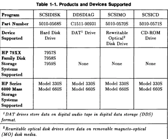
Table 1-1 provides information on the products and devices supported by the mass storage diagnostic programs. Each diagnostic program supports one device included in disk storage or mass storage systems.
Note The mass storage diagnostic programs cannot be ordered by part number. They reside on a system in Disk Storage Systems Division and must be downloaded from that system into your HP Portable PLUS computer. The part numbers in Table 1-1 are provided only for the purpose of reporting defects in the diagnostic programs.
Table 1·1. Products and Devices Supported
Program SCSI DISK DDSDIAG SCSIMO SCSICD
l
Part Number 5010-05685 C1511-90931 5010-05705 5010-05715Device Hard Disk DATl Drive Rewritable CD-ROM
Supported Drive Optical2 Drive
Disk Drive
HP 79XX 7957S Family Disk 7958S
Storage 7959S None None None
Systems Supported
HP Series Model 330S Model 330S Model 330S Model 330S 6000 Mass Model 660S Model 660S Model 660S Model 660S Storage
Systems Supported
1 DAT drives store data on digital audio tape in digital data storage (DDS) format.
2 Rewritable optical disk drives store data on removable magneto-optical (MO) disk media.
[image:17.397.73.367.87.331.2]Diagnostic Features
The mass storage diagnostic programs include commands which provide the following important diagnostic features:
• Internal self-test diagnostic routines.
• Media tests.
• Reassignment of defective blocks on media (SCSIDISK and SCSIMO only.) • Access to Maintenance logs (SCSIDISK and DDSDIAG only).
• Error and fault reporting. Internal Diagnostics
The DIAGNOSTICS command invokes internal self-test diagnostic routines resident within controller firmware. These diagnostic routines perform small functional tests of the servo, read/write, and controller functions of the device. The CE Handbook for each product contains information on the status of self-test indicators when self-test diagnostics pass and fail.
Media Tests
Media tests are powerful tools to determine the integrity of the media and read/write circuitry. The RO MEDIA TEST command enables the user to perform read-only media tests, and the WTR MEDIA TEST command enables the user to perform write-then-read media tests.
Block Reassignment
The SCSIDISK and SCSIMO diagnostic programs include the REASSIGN BLOCK command, which enables the user to reassign a defective block to a spare track on the media.
Error and Fault Reporting
If a command fails to complete successfully, the device returns a status of Check Condition. The Initiator then displays a failure message, followed by the extended sense bytes for the failed command.
The user can also request the status of a device at any time with the REQUEST SENSE command. The CE Handbook for the device includes the codes for the REQUEST SENSE extended sense data fields supported by the device.
Maintenance Logs
The ACCESS LOGS command in the SCSIDISK diagnostic program provides access to the following Maintenance logs: Usage Log, Data Error Log, and Hardware Error Log. The CE Handbook for the product being tested contains device-specific information about hard disk drive Maintenance logs.
The ACCESS LOGS command in the DDSDIAG diagnostic program provides access to the following Maintenance logs: Fault Log, Error Rate Log, and Tape Log. The CE Handbook for the product being tested contains device-specific information about digital audio tape drive Maintenance logs.
Setting Up Diagnostic Equipment
The following paragraphs provide information on loading diagnostic programs into an HP Portable PLUS and connecting diagnostic equipment to a mass storage system.
Note The mass storage diagnostics were designed for use with the HP Portable PLUS. However, with the proper HP-IL interface and software, they can also be used with the HP 150 or Vectra PC (refer to "Equipment Required").
Equipment Required
The following equipment is required to test mass storage system devices with mass storage diagnostic programs:
• HP Portable PLUS Computer
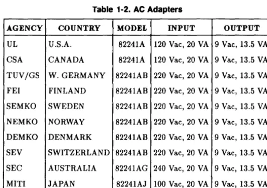
• HP Series 82241 AC Adapter (refer to Table 1-2)
• HP-IL/SCSI Interface Assembly, part number 5061-3066 (includes the HP-IL/SCSI Interface, the Field Service SCSI Cable, and the Using Mass
Storage Diagnostics with the HP-IL Interface manual) • SCSI Terminator, part number 1252-2297
• HP 82167B HP-IL Cables
• HP-IL Printer (optional)
Note
Note
If you are using the HP 150, you need to install the following: • HP 45643A HP-IL/Parallel Card for HP 150
• HP Series 100 Extended I/O Applications, part number 45643-13001
If you are using the HP Vectra PC, you need to install the following:
• HP 82973A HP-IL Interface Card for HP Vectra PC
• HP 82973A HP-IL Interface Software for HP Vectra PC, Rev. E, part number 82973-12005
Caution
•
AGENCY
UL
CSA
TUVjGS
FEI
SEMKO
NEMKO
DEMKO
SEV
SEC
MITI
Use only a Hewlett-Packard Series 82241 AC Adapter to provide power to the HP-IL/SCSI Interface. Table 1-2 lists the adapters approved for use with the HP-ILjSCSI Interface.
Table 1·2. AC Adapters
COUNTRY MODEL INPUT OUTPUT
U.S.A. 82241A 120 Vae, 20 VA 9 Vae, 13.5 VA
CANADA 82241A 120 Vae, 20 VA 9 Vae, 13.5 VA
W.GERMANY 82241AB 220 Vae, 20 VA 9 Vae, 13.5 VA
FINLAND 82241AB 220 Vae, 20 VA 9 Vae, 13.5 VA
SWEDEN 82241AB 220 Vae, 20 VA 9 Vae, 13.5 VA
NORWAY 82241AB 220 Vae, 20 VA 9 Vae, 13.5 VA
DENMARK 82241AB 220 Vae, 20 VA 9 Vae, 13.5 VA
SWITZERLAND 82241AB 220 Vae, 20 VA 9 Vae, 13.5 VA
AUSTRALIA 82241AG 240 Vae, 20 VA 9 Vae, 13.5 VA
JAPAN 82241AJ 100 Vae, 20 VA 9 Vae, 13.5 VA
[image:21.402.82.348.179.366.2]Loading Diagnostic Programs
Note The instructions for loading diagnostic programs into your HP Portable PLUS are not included in this manual. The instructions reside on a system at Disk Storage Systems Division, and can be obtained by performing the steps below.
To obtain information on how to load the mass storage diagnostic programs into your HP Portable PLUS, perform the following steps:
1. Send an HPDESK message to address DSSDISK. An auto answer message will automatically be returned to your HPDESK number.
2. At the Intray > prompt, list the items to see which item number corresponds to AUTO ANSWER MESSAGE.
3. Read the auto answer message.
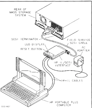
Connecting Equipment
Figures 1-1 and 1-2 show how to connect the equipment required to use the mass storage diagnostic programs with the HP Portable PLUS. If you are connecting a printer to the Portable PLUS, refer to the following documentation for configuration information: Using the Portable PLUS (reorder number 45711-90002) and the user manual for the printer you are connecting.
To connect the diagnostic equipment to the mass storage system, perform the following steps:
1. Remove ac power from the computer system.
2. Set the LlNE- switch on the mass storage system to the 0 (out) position. 3. Disconnect the SCSI bus cable(s) from the mass storage system.
4. Connect the field service SCSI cable to the HP-IL/SCSI interface. Make sure the connector on the field service SCSI cable is properly oriented before connecting it to the interface (see Figure 1-1).
5. Connect the other end of the field service SCSI cable to a SCSI connector on the rear panel of the mass storage system.
6. Connect the SCSI terminator to the other SCSI connector on the rear panel of the mass storage system.
7. Connect the computer and the printer to the HP-IL/SCSI interface using HP-IL cables (see Figure 1-2). If the printer is not being used, connect the computer to the HP-IL/SCSI interface as shown in Figure 1-1.
8. Connect the cable from the ac adapter to the input power connector on the HP-IL/SCSI interface.
REAR OF
MASS STORAGE
SYSTEM
SCSI TERMINATOR
RESET BUTTON
CEDIAG1
SERVICE
CABLE
HP-IL CABLES
HP PORTABLE PLUS
COMPUTER
Figure 1·1. Diagnostic Equipment Connections with Portable PLUS Only
[image:24.399.28.338.91.457.2]REAR OF MASS STORAGE
SYSTEM HP-IL
THINKJET PRINTER
CEDIAG2
PORTABLE PLUS COMPUTER
SERVICE CABLE
Figwe 1-2. Diagnostic Equipment Connections with Printer and Portable PLUS
Testing Equipment
After connecting the diagnostic equipment, you should perform a power-on test of the equipment as follows:
1. Plug the Series 82241 AC Adapter into a suitable ac source.
2. Monitor the LED display on the HP-ILjSCSI interface module as the module performs its internal self-test. Successful execution of the self-test routine is indicated when the LED indicator flashes five times and then goes off.
3. If the module passes its self-test, go to step d. A module self-test failure may be caused by a problem with the field service cable connecting the module and the drive. Check the cable carefully then press the module Reset button to restart the self-test routine. If the self-test routine fails again, the module is probably defective. Replace the module and begin again at step a.
4. Switch on power to the disk storage or mass storage system, Portable PLUS, and printer (if used). Check for normal operation of all the equipment and the disk storage or mass storage system.
Note Even though a device may fail its power-on self-test, the diagnostic program for the device may still be used to
troubleshoot the device. If the device responds to a REQUEST SENSE command, failure information can be retrieved from the device.
Running a Diagnostic Session
A diagnostic session is defined as a period of time during which a diagnostic program starts running on an HP Portable PLUS, commands are entered from the command prompt, and a diagnostic program is ended by returning to the A:\ prompt.
The following paragraphs provide information on starting a diagnostic session using one of the mass storage diagnostic programs to test a mass storage device, entering commands during a diagnostic session, printing the dialog from a diagnostic session, and ending a diagnostic session. After ending a diagnostic session, you can start a new diagnostic session using a different diagnostic program to test another mass storage system device.
Starting a Session
To start a diagnostic session, perform the following steps: 1. Select DOS Commands in the P.A.M. main menu. 2. Press Start AppliC:'.
3. At the A: \ prompt, change the directory to the one where the diagnostic program is stored.
4. Type the name of the diagnostic program (SCSIDISK, DDSDIAG, SCSIMO, or SCSICD) and press [Return
J.
The name of the diagnostic program, copyright,version, and part number is displayed at the top of the screen with the following prompt:
Enter Initiator ID (0-7)[7]:
5. Enter the desired Initiator ID and press (Return
J.
The ID can be any value from 0 to 7. When connected to a single drive, the Initiator ID must be different than the ID assigned to the Target. When connected to a SCSI bus, the Initiator ID must be different from the addresses of all other active devices on the bus. The default Initiator ID is 7.6. The following prompt is displayed: Enter SCSI Target ID (0-7)[0]:
7. Enter the Target ID and press [Return
J.
The Target ID must correspond to the setting of the SCSI address switch on the drive under test. If necessary, refer to the appropriate drive documentation for help in interpreting the address switch setting. The default Target ID is O.Note If you need to change the Initiator ID or the Target ID, use the ID command (refer to Table 1-3).
8. Depending on which diagnostic program is loaded, one of the following command prompts is displayed:
SCSIDISK> DDSDIAG> SCSIMO> SCSI CD>
9. The program is now ready to accept commands from the user.
Command Description Format
The following format is used in chapters 2 through 5 to describe mass storage diagnostic commands. Chapters 2 through .5 contain detailed information on the commands included in the SCSIDISK, DDSDIAG, SCSIMO, and SCSICD diagnostic programs. The HELP command can be used to display a list of all the commands available in a diagnostic program, along with a brief description of the commands.
COMMAND NAME
COMMAND NAME
COMMAND ABBREVIATION
Description
The Description section explains the function and operation of the command.
Examples
The Examples section provides examples which show the operation of the command and the user interface. If there are several examples, each example is usually preceded with a bulleted explanation. However, examples that are simple or self-explanatory may not be preceded with bulleted explanations.
Related Commands
The Related Commands category lists all commands which are functionally related to the command being described. If there are no functionally related commands, this category will not appear.
General Information 1·17
Entering Commands
Note Diagnostic commands are not case sensitive. The following commands are equivalent: REQUEST SENSE, REQuest sense, Request Sense, request sense.
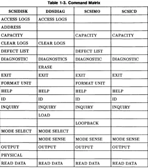
At the diagnostic command prompt, a command can be entered using the abbreviated form of the command or the full command name in any combination of upper case and lower case letters. Table 1-3 provides a matrix of the mass storage diagnostic programs and the commands in this manual.
Note Whenever you need information about the mass storage device you are testing, you can enter the INQUIRY command. The INQUIRY command will display the Target ID, which is the SCSI address of the device you are testing, as well as the following device-specific information:
• Product ID
• Firmware revision • Maximum address • Block (or record) size
Printing a Session
Normally, the dialog that occurs while a command is being executed is displayed on the Portable PLUS screen. If you want to print the dialog, perform the following steps:
1. Type OUTPUT at the command prompt and press (Return
J.
2. Type PRN and press (Return
J.
To redirect the dialog to the console screen, perform the following steps:
1. Type OUTPUT and press (Return
J.
2. Type CON and press (Return
J.
Ending a Session
When you want to end a diagnostic session, type EXIT and press (Return
J.
TheA: \ prompt will then appear.
Table 1·3. Command Mabix
SCSIDISK DDSDIAG SCSIMO SCSICD
ACCESS LOGS ACCESS LOGS ADDRESS
CAPACITY CAPACITY CAPACITY
CLEAR LOGS CLEAR LOGS
DEFECT LIST DEFECT LIST
DIAGNOSTIC DIAGNOSTICS DIAGNOSTIC DIAGNOSTIC
ERASE
EXIT EXIT EXIT EXIT
FORMAT UNIT FORMAT UNIT
HELP HELP HELP HELP
ID ID ID ID
INQUIRY INQUIRY INQUIRY INQUIRY
LOAD
LOOPBACK MODE SELECT MODE SELECT
MODE SENSE MODE SENSE MODE SENSE
OUTPUT OUTPUT OUTPUT OUTPUT
PHYSICAL
READ DATA READ DATA READ DATA READ DATA
[image:32.397.35.328.85.418.2]SCSIDISK
READ FULL IBTOf"'K u '-' ..
REASSIGN BLOCK
REQUEST SENSE
RO MEDIA TEST SEEK
VERIFY
WTR MEDIA TEST
Table 1·3. Command Matrix (continued)
DDSDIAG SCSIMO SCSICD
REASSIGN BLOCK
REQUEST SENSE REQUEST SENSE REQUEST SENSE RESET
REWIND
RO MEDIA TEST RO MEDIA TEST RO MEDIA TEST
SEEK SEEK
SPACE TEST UNIT READY UNLOAD VENDOR GROUP
VERIFY WRITE DATA
WRITE FILEMARKS
WTRMEDIA WTR MEDIA
TEST TEST
[image:33.397.70.362.87.414.2]2
SCSIDISK Commands
This chapter provides information on the commands included in the SCSIDISK diagnostic program.
The SCSIDISK diagnostic program transfers data and commands between a hard disk drive and an HP Portable PLUS via a HP-ILjSCSI interface. Hard disk drives store data on nonremovable disk media.
ACCESS LOGS
AC
Description
The ACCESS LOGS command displays the contents of the Data Log or the Hardware Error Log, which reside on the Target's maintenance track. The Data Log includes the Usage Log and the Data Error Log.
The Target records the occurrence of events such as data errors and hardware faults on the maintenance track. Detailed information concerning how the Target manages the maintenance log is product specific and is included in the CE Handbook for the product.
The logical addresses are displayed in either block or three-vector mode as defined by the ADDRESS command. Corresponding physical addresses can also be displayed using the PHYSICAL command.
U sage Log Contents
The Area field indicates what portion of the Target's media is covered by the log data. An Area of "Volume" indicates that the log refers to the entire Target.
The Access Count field indicates the number of times the media was accessed since the last hardware error occurred or the log was cleared. This field is reset to zero each time an entry is added to the Hardware Error log. To determine the total number of media accesses, the Hardware Error log Access Count entries must be combined with the Usage log Access Count field. If no Hardware Error log entries are included in the maintenance log, the Usage log Access Count field reflects the total number of media accesses. The number of accesses represented by the Access Count field are shown in table 3-1.
The Blocks Accessed field is the count of the blocks read over the entire disk drive.
ACCESS LOGS
The First Retry Count field indicates the number of instances when the data recovery algorithm was forced to perform data read retries and the data was recovered on the first retry.
The Multiple Retry Count field indicates the number of times data was not recovered on the first retry. This field is incremented only once per complete recovery action, not once for each individual retry within a multiple-retry recovery.
Data Error Log Contents
The Logical Block Address field contains the address of a data block that encountered multiple read retries during one or more data error recovery attempts.
The Error Type field indicates the type of data error the block encountered. The contents of this field is product specific.
The Count field is incremented each time the specified block is uncorrectable or requires multiple retries in a given transaction. This field is incremented only once for each data recovery attempt.
The Error byte encodes specific data error information. Because the coding is bit-significant, multiple errors at the same location will have their respective bits merged into the reported byte. The content of this byte is product specific.
Hardware Error Log Contents
The Logical Block Address field contains the address of the data block that the disk drive was attempting to access when the error occurred.
The Internal Device Status field contains an error code corresponding to the additional sense code returned by the REQUEST SENSE command. The values in the Access Count field must be combined with the values of the Access Count field in the Usage log to yield the total number of media accesses. The number of accesses represented by the Access Count field are shown in Table 2-1.
ACCESS LOGS
Table 2-1. Hard Disk Drive Access Count Range values
VALUE MINIMUM
or
MAXIMUMor
(HEX) ACCESS RANGE ACCESS RANGE0 No Accesses No Accesses
1 1 1
2 2 10
3 11 100
4 101 1,000
5 1,001 10,000
6 10,001 100,000
7 100,001 500,000
8 500,001 1,000,000
9 1,000,001 5,000,000
A 5,000,001 10,000,000 B 10,000,001 50,000,000
C 50,000,001 100,000,000
D 100,000,001 500,000,000 E 500,000,001 1,000,000,000
r
1,000,000,001 >1,000,000,001 [image:38.399.87.281.90.383.2]ACCESS LOGS
Examples
• The following example shows how to read the Data log, which includes the U sage log and the Data Error log. Logical addresses are displayed in block mode.
SCSIDISK> ACCESS LOGS
Types of logs: D - Data Log
H - Hardware Error Log
Which log [D]? ~
Usage and Data Error Log
========================
Area = xxxxxxxxx Access Count = n Blocks Accessed
=
n First Retry Count n Multiple Retry Count = nLogical Error
Block Address Type
=================
n xxxxx
Count Error
========
n b
• The following example shows how to read the Hardware Error log. Logical addresses are displayed in three-vector mode.
SCSIDISK> ACCESS LOGS
Types of logs: D - Data Log
H - Hardware Error Log
Which log [D]? ~
ACCESS LOGS
Hardware Error Log
Logical Cyl Head Sect
Internal Access Device Status Count
================= =============
n n n
Related Commands
ADDRESS PHYSICAL
2-6 SCSIDISK Commands
ADDRESS
ADDRESS
AD
Description
The ADDRESS command controls the mode in which logical addresses are displayed: block or three-vector. This command can also be used to convert a logical address from one mode to the other.
The Target's media is logically organized as a contiguous series of data blocks. Each block is assigned a value, beginning with zero and increasing to a maximum number which represents the last addressable data block. Each logical block address corresponds to a logical three-vector address, represented by cylinder, head, and sector values.
The program can display logical addresses in either mode. The ADDRESS comma.nd controls the state of an address in the diagnostic program. The address flag determines whether logical addresses will be displayed in block or three-vector mode. The ADDRESS command can also be used to convert a logical block address to its three-vector equivalent, or vice versa.
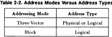
The ADDRESS command controls the display of logical addresses only. The display of physical addresses is controlled with the PHYSICAL command. Unlike logical addresses, physical addresses can only be displayed in three-vector mode. The relationship between each address type and its addressing mode is shown below:
Table 2·2. Address Modes Versus Address Types
Addressing Mode Address Type
Three-Vector Physical or Logical
Block Logical
In the following examples, the user defines the desired logical addressing mode, block (B) or three-vector (V). The specified address is then converted and displayed in the desired mode. The address flag is also set to display
[image:41.396.119.307.375.438.2]ADDRESS
all subsequent logical addresses in the same mode. To change the return addressing mode without performing an address conversion, simply use default values for all address prompts. The default addressing mode is three-vector.
Examples
• The following example shows how to convert a three-vector address to a block address, which sets the return addressing mode to block mode. SCSIDISK> ADDRESS
Do you want the result to be a Block or Vector address (B/V) [V]? B
Cylinder address (0 - n)[n]? n
Head address (0 - n)[n]? n
Sector address (0 - n)[n]? n
Cylinder n, Head n, Sector n
is Block n
The return addressing mode is now set to BLOCK .
• The following example shows how to convert a block address to a
three-vector address, which sets the return addressing mode to three-vector mode.
SCSIDISK> ADDRESS
Do you want the result to be a Block or Vector address (B/V) [V]? V
Enter block address (0 - n)[n]: n
ADDRESS
Block address n
is Cylinder n, Head n, Sector n
The return addressing mode is now set to THREE-VECTOR.
Related Commands
ACCESS LOGS CAPACITY DEFECT LIST
CAPACITY
CA
Description
The CAPACITY command allows the Initiator to determine the maximum capacity of the Target. The Target returns the address of its last addressable logical block. The address is displayed in block or three-vector mode as defined by the ADDRESS command. The current block size and the drive capacity are also displayed.
Although the physical capacity of the Target remains fixed, the address of the last data block is determined by block size. The larger the block size, the lower the address of the last addressable logical block.
Examples
• The following example shows how the Target returns the address of its last addressable logical block. The address is displayed in block mode.
SCSIDISK> CAPACITY
Maximum Block Address
=
nBlock Length
=
nDrive Capacity = n bytes
• The following example shows the address of the last logical block displayed in three-vector mode.
SCSIDISK> CAPACITY
Maximum Address: Cyl n, Head n, Sector
=
nBlock Length
=
nDrive Capacity = n bytes
Related Commands
ADDRESS
CAPACITY
CLEAR LOGS
CLR
Description
The CLEAR LOGS command clears the Target's Data Log (Data Error Log), Usage Log, and Hardware Error Log.
Examples
SCSIDISK> CLEAR LOGS
CAUTION! This command will destroy service-related information. The Data log, Usage log, and Hardware Error log will be cleared.
Do you wish to continue (YIN) [N]? Y
All logs cleared.
Related Commands
ACCESS LOGS
DEFECT LIST
DEFECT LIST
DEF
Description
The DEFECT LIST command displays the Target's primary defect list or growing defect list, which may include addresses on the following tracks: • Maintenance tracks
• Spare tracks • User Data tracks • Log tracks • Defect List tracks
There is also an option that allows both defect lists to be stored to files in the Portable PLUS. The primary defect list is stored in a file called PLIST.SAV, and the growing defect list is stored in a file called GLIST.SAV.
Both defect lists return the logical address field in either block or three-vector mode as defined by the ADDRESS command. In three-vector mode a sector value of "all" indicates that the entire track has been spared. The corresponding physical address can also be displayed using the PHYSICAL command.
Note No logical address is provided for spare track, maintenance track, or log track entries. These tracks can only be accessed using physical addressing.
The primary defect list contains the addresses of the permanent media defects that were identified in the factory during the manufacturing process.
DEFECT LIST
The growing defect list contains the addresses of media defects that are identified after the hard disk drive is installed at a customer site. This includes media defects that are identified by the Initiator during formatting and media defects that are specified in REASSIGN BLOCK commands. The growing defect list does not include the primary defect list.
Examples
• The following example shows how to display the growing defect list. The logical address field is displayed in three-vector mode.
Note In the example below, the address of the spare track is not displayed because the spare track is not included in the user data area of the disk. Spare tracks only have physical addresses. To display the physical address of a spare track, you must use the PHYSICAL command.
SCSIDISK> DEFECT LIST
Defect List options:
G - display growing defect list P - display primary defect list B - display both lists
S - store lists to files
Which option [G]? G
Groving Defect List:
Logical
Cyl Head Sect Type
n n
n n
n
n
User Data Spare Track User Data
DEFECT LIST
• The following example shows how to display the primary defect list. The logical address field is displayed in block mode and includes the current block size. When an entire track has been spared, the logical blocks on the spared track are displayed as a range of blocks.
SCSIDISK> DEFECT LIST
Defect List options:
G - display groving defect list P - display primary defect list B - display both lists
S - store lists to files
Which option [G]? ~
Primary Defect List:
Logical Block Address
(Block Size
=
n) Typen User Data
n - n User Data
DEFECT LIST
• The following example shows how the primary defect list is displayed if the physical addressing mode has been enabled by the PHYSICAL command. The logical address field is displayed in block mode, as defined by the ADDRESS command, and the physical address field is displayed to the right.
SCSIDISK> DEFECT LIST
Defect List options:
G - display groving defect list P - display primary defect list B - display both lists
S - store lists to files
Which option [G]? ~
Primary Defect List:
Physical Logical Block Address
(Block Size
=
n) Type Cyl Head Sect======================
n n
2·16 SCSIDISK Commands
User Data User Data
n n
n n
DEFECT LIST
• The following example shows how to store the primary defect list and growing defect list to Portable PLUS files.
SCSIDISK> DEFECT LIST
Defect List options:
G - display growing defect list P - display primary defect list B - display both lists
S - store lists to files
Which option [G]? S
Created file is PLIST.SAV.
Created file is GLIST.SAV.
Related Commands
ADDRESS PHYSICAL
DIAGNOSTIC
DI
Description
The DIAGNOSTIC command invokes the Target's power-on self-test diagnostic sequence. A loop option allows the diagnostic to be repeated a specified number of times.
Note
Examples
Refer to the CE Handbook for the device being tested for device-specific error codes that correspond to self-test failures.
SCSIDISK> DIAGNOSTIC
Enter the loop count (1 - 256) [1]? n
Send Diagnostic Pass
=
nEXIT
EXIT
E
Description
The EXIT command stops execution of the SCSIDISK program and returns the A: \ prompt.
Examples
SCSIDISK> EXIT
End of Program.
A:\
FORMAT UNIT
F
Caution
•
Description
The FORMAT UNIT command will destroy user data or maintenance track information on the disk. You should back up all user data before executing the FORMAT UNIT command.
The FORMAT UNIT command formats the Target media so that all data blocks can be accessed. When formatting all of the media surfaces, all user data is lost and all log information is cleared. The FORMAT UNIT command can also be used to reformat the Target maintenance track only, without formatting user data tracks.
A successfully executed FORMAT UNIT command installs the current MODE SELECT operating parameters as the Target's saved values. Therefore, before executing a FORMAT UNIT command on all media surfaces, the current values of the Target's changeable parameters should be checked to ensure they are set to the desired values.
Prior to formatting all media surfaces, the user must define what defect information to retain. If all spares are kept, the primary defect list and the growing defect list are both saved. If only primary spares are retained, the primary defect list is kept but the growing defect list is deleted.
In some situations it may be necessary to reformat only the maintenance track or one of the maintenance tracks. The FORMAT UNIT command includes an option to do this. Refer to the appropriate CE Handbook for details on how the Target responds to reformatting of these tracks.
FORMAT UNIT
Examples
• The following example shows how to format the media and retain all spares.
Note
SCSIDISK> FORMAT UNIT
CAUTION! THIS COMMAND WILL DESTROY DATA.
Do you want to:
A retain All spares
P retain only Primary spares
M reformat Maintenance/log track only E Exit
Option [E)? A
CAUTION! THIS COMMAND WILL DESTROY ALL DATA ON THE DISK.
Formatting will take approximately n minutes.
Do you wish to continue (Y/N) [N]?
!
Formatting in progress (hh:mm:ss)
Formatting completed. (hh:mm:ss)
Formatting took n minutes and n seconds.
The program displays the exact time the formatting started. If the formatting has not completed in a reasonable amount of time, the FORMAT UNIT command will time-out and terminate.
FORMAT UNIT
• The following example shows how to reformat the maintenance track only.
SCSIDISK> FORMAT UNIT
CAUTION! THIS COMMAND WILL DESTROY DATA.
Do you want to:
A retain All spares
P retain only Primary spares
M reformat Maintenance/log track only E Exit
Option [E]?
!!
Do you want to:
L
=
reformat the Log track M reformat a Maintenance track E :III: ExitOption [E]?
!!
CAUTION! This command will destroy all mode operating parameters. Mode Select is required to restore operating parameters following this command.
Are you certain you wish to continue (Y/N) [N]? Y
• The following example shows how to reformat the log track.
SCSIDISK> FORMAT UNIT
CAUTION! THIS COMMAND WILL DESTROY DATA.
Do you want to:
A = retain All spares
P
=
retain only Primary sparesM
=
reformat Maintenance/log track only E=
ExitOption [E]? M
Do you want to:
L
=
reformat the Log track M reformat a Maintenance track E=
ExitOption [E]? L
Are you certain you wish to continue (Y/N) [N]? Y
Head address (0 - n) [n]? n
Related Commands
MODE SELECT
FORMAT UNIT
HELP
H
Description
The HELP command displays a list of all the commands supported by the SCSIDISK program, along with a brief description of each command. The list of commands is displayed one screen at a time. Press the space bar to display each successive screen.
To enter a command, type the full command name shown in the left-hand column or type the abbreviated form of the command shown as upper-case letters within the full command.
Examples
SCSIDISK> HELP
ACcess logs
ADdress
CApcity
CLeaR logs CLR
DEFect list
DIagnostic
Exit
Format unit
- Display the Usage log, Data Error log, or the Hardware Error Log.
- Convert block address to vector, etc.
- Determine capacity of Target.
- Clear ALL of the drive logs.
Display either the growing or the primary defect list.
- The Target will execute its internal diagnostics.
- Exit the program.
- Format the media.
Help
ID
INquiry
Mode Select MS
Output
Physical
Read Data RD
Read Full block RF
REASsign block
REQuest sense
RO media test
Seek
Verify
WTR media test
- Display this help file.
- Change SCSI Initiator ID or Target ID.
- Display Target and program parameters.
- Modify the Target's parameters.
- Directs the output to the console, printer, or file.
- Enable or disable the display of physical addresses.
- Display the contents of a selected block.
- Read entire block and display the header, data and ECC field contents. ECC field contents.
- Reassign a defective block.
- Read Sense data from Target, format and display the results.
- Perform Read-Only Media Test.
- Issue the SCSI Seek command. You can select random, alternate, single, or butterfly seeks.
- Selected or random area of Target is verified by ECC check only.
- Perform Write-Then-Read Media Test.
HELP
10
ID
Description
The ID command is used to change the SCSI ID of the Initiator or the SCSI ID of the Target. The Initiator is the HP Portable PLUS and the Target is the hard disk drive being tested.
The SCSI ID of the Target (Target ID) must match the SCSI address of the hard disk drive being tested. The SCSI address of the hard disk drive is either set at the factory, or is set by the operator when the hard disk drive is installed into the mass storage system. (Refer to the appropriate CE Handbook for information on setting the hard disk drive SCSI address switches.) The default Target ID value is zero.
The SCSI ID of the Initiator (Initiator ID) must match the SCSI address of the HP-IL/SCSI interface. The default Initiator ID value is seven.
Examples
SCSIOISK> 10
Enter Initiator 10 (0-7) [7]? n
Enter SCSI Target 10 (0-7) [O]? n
Related Commands
INQUIRY
INQUIRY
INQUIRY
IN
Description
The INQUIRY command instructs the Target to return its parameter information. This information is then displayed, along with the settings of various program variables.
The INQUIRY command returns a Check Condition status if the Target cannot return the requested data. Inquiry data will be returned even though the Target may not be ready for other commands.
If an INQUIRY command is received from an Initiator with a pending Unit Attention condition (before the Target reports a Check Condition status), the Target executes the INQUIRY command but does not clear the Unit Attention sense key. This is also true for a pending Hardware Error sense key.
The following example includes a general description of the information returned by the INQUIRY command. The actual values returned by the Target are product specific and are listed in the appropriate CE Handbook.
The first block of information shown in the example contains information describing the Target. The Direct Access Device field indicates whether the Target uses fixed or removable media. The Vendor ID, Product ID, and Firmware Revision fields are all product specific. The HP-IL/SCSI Revision field indicates the revision of firmware installed in the HP-IL/SCSI interface module.
The second block of information displays the current setting of various program parameters. The program parameters include SCSI Initiator ID, SCSI Target ID, block size, physical address display setting, addressing mode (block or three-vector), and selected output device.
The final block of information describes Target addressing and capacity parameters. This information is product specific and is listed in the appropriate CE Handbook.
INQUIRY
Examples
SCSIDISK> INQUIRY
Direct Access Device Vendor ID
Product ID Firmware Revision HP-IL/SCSI Revision
SCSI Initiator ID SCSI Target ID Physical Addresses Address Mode Output Device
Max Block Address Max Cylinder Address Max Head Address Max Sector Address Bytes Per Track Block Size
Related Commands
ID
2·28 SCSIDISK Commands
Fixed Media xx
{C2212A} {C2213A} xxxx
xxx x
= n n
{Enabled} {Disabled} {Three-Vector} {Block} xxxxxxx
=
n=
n=
n=
nMODE SELECT
MODE SELECT
MS
Description
The MODE SELECT command provides a means for the Initiator to define various Target operating parameters. During SCSIDISK program initialization, the SCSIDISK diagnostic program determines which Target parameters are changeable. These values can then be changed using the MODE SELECT command.
The MODE SELECT command updates the current operating parameters. The only changeable values supported are the following Error Recovery values: Read Retry Count and Recovery Time Limit.
The Retry Count specifies the number of times that the Target should attempt its read recovery algorithm.
The Recovery Time Limit is the maximum time that the Target will attempt error recovery actions in order to correctly recover data. This field is defined in one (1) millisecond increments.
Examples
• The following example shows how to modify the Target's changeable parameters.
SCSIDISK> MODE SELECT
Select the value of the following parameters:
Retry Count (0 - 255) [8]? n
Recovery Time Limit (0 - 255) [255]? n
Current parameters have been modified.
OUTPUT
o
Description
The OUTPUT command directs the program output to the Portable PLUS console, a printer, or a file. All command prompts continue to be displayed on the Portable PLUS console, but output information is directed to the specified device or file. The OUTPUT command is useful for recording the results returned by a specific command. For example, when performing an ACCESS LOGS command, the contents of the logs can be printed or stored in a file for later examination. The default output device is the console (CON).
The output file can have an extension of three characters in length (for example, test.txt).
Note When directing output to a ThinkJet Printer connected to a Portable PLUS, the printer will respond to the PRN setting.
Examples
• The following example shows how to direct output to the printer.
SCS101SK> OUTPUT
Enter output file. printer 10 (PRN). or console (CON) [CON]: PRN
Output directed to PRN.
OUTPUT
• The following example shows how to direct output to a file called LIST!. SCSIDISK> OUTPUT
Enter output file, printer ID (PRN), or console (CON)
[CON]: LISTi
Output directed to LIST1 .
• The following example shows how to direct output to the console. SCSIDISK> OUTPUT
Enter output file, printer ID (PRN), or console (CON) [CON]: CON
Output directed to console.
PHYSICAL
p
Description
The PHYSICAL command enables or disables the display of physical address information each time the command is executed. The program always displays logical address information in the mode defined by the ADDRESS command. If physical addressing is enabled, the program also displays physical addresses in three-vector mode.
The data tracks on the disk media are organized as a contiguous series of logical blocks. Each logical block corresponds to a physical location on the media. The two addresses differ because physical addressing takes into account the presence of nondata tracks (spare tracks and maintenance tracks) and logical addressing does not. The exact relationship between logical and physical addresses is product specific.
Examples
• The following example shows how to enable the display of physical addresses, then disable the display of physical addresses.
SCSIDISK> PHYSICAL
Physical addresses enabled.
SCSIDISK> PHYSICAL
Physical addresses disabled.
Related Commands
ACCESS LOGS DEFECT LIST
READ DATA
READ DATA
RD
Description
The READ DATA command transfers one block of data from the Target to the Initiator. The data is displayed on the currently defined output device. The logical block address can be specified in either block or three-vector mode. The ASCII representation of the data is displayed on the right side of the screen. If the seek performed during the read operation is successful, the Target checks for errors and performs read retries, if necessary. Unrecoverable data errors cause the read operation to terminate with the transmission of data up to, but not including, the unrecoverable physical block. This may cause partial transmission of a logical block, but no erroneous data will be transferred to the Initiator.
Examples
• The following example shows how to read a block of data from an HP 7957S, 7958S, or 7959S disk drive.
SCSIDISK> READ DATA
Do you want Block or Vector addressing (B/V) [V]? B
Enter block address (0 - n)[n]: n
Data (hex):
1: HH HH HH HH HH HH HH HH HH HH 11: HH HH HH HH HH HH HH HH HH HH 21: HH HH HH HH HH HH HH HH HH HH
251: HH HH HH HH HH HH
READ DATA
Note The ASCII representation of the hex data field is also displayed on the right-hand side of the screen.
Related Commands READ FULL BLOCK
READ FULL BLOCK
READ FULL BLOCK
RF
Description
The READ FULL BLOCK command displays the following information fields for the specified logical or physical block: header, data, and ECC. The type of track (user or spare) on which the block resides is also displayed. The Target's block size and format is product specific and is listed in the appropriate CE Handbook.
Note
Examples
Certain areas on the Target's media lie outside the logical address range. These areas include spare tracks, log tracks, and maintenance tracks. Physical addressing must be used when executing a READ FULL BLOCK command on these areas of the media.
• The following example shows how to read one full block from an HP 79575, 79585, or 79595 hard disk drive using physical block addressing. If logical block addressing is used, the block address is still displayed in logical three-vector format.
SCSIDISK> READ FULL BLOCK
Access physical or logical addresses (P/L) [L]? P
Physical cylinder address (0 - n)[n]? n
Head address (0 - n)[n]? n
READ FULL BLOCK
Sector address (0 - n)[n]? n
{Logical Cyl}
=
n Physical Cyl = n Logical Head=
n Logical Sector n{DefectivG Field spare track} {Defective Factory spare track} {Reserved}
{Spare track assigned in Field. (Growing defect)} {Spare track assigned in Factory. (Primary defect)} {User track}
{Log track}
{Maintenance track} {Unassigned spare track}
Header values(hex): 1: HH HH HH HH
Data (hex):
1: HH HH HH HH HH HH HH HH HH HH 11: HH HH HH HH HH HH HH HH HH HH 21: HH HH HH HH HH HH HH HH HH HH
251: HH HH HH HH HH HH
Note
ECC bytes (hex):
1: HH HH HH HH HH HH
The ASCII representation of the hex data field is also displayed on the right-hand side of the screen.
READ FULL BLOCK
• The following example shows how to read one full block from an HP C2212A or C2213A hard disk drive using physical block addressing. If logical block addressing is used, the block address is still displayed in logical three-vector format.
Note In this example, the following typographical conventions apply: Message lines in curly brackets ({}) are alternative message lines that may appear on the Portable PI,US screen. Message lines without curly brackets are messages that always appear on the Portable PLUS screen.
SCSIDISK> READ FULL BLOCK
Access Physical or Logical addresses (P/L) [L]? P
Physical cylinder address (0 to n)[n]? n
Head address (0 to n)[n]? n
Sector address (0 to n)[n]? n
The following message line will appear only if the block is a logical address and the block has been spared:
{New location:}
The block address of the block being read will always appear:
Physical Cyl n
{Logical Cyl n}
Head = n Logical Sector
=
nIf the block has been spared, the following message lines will appear:
{Spared physical cyl n}
{Spared head = n}
READ FULL BLOCK
If the block has not been spared, one of the following message lines will appear:
{User data track} {Maintenance track} {Log track}
{Defect List track} {Unassigned spare track}
Track has not been spared.
If the spare sector on the track has been used, the following message line will appear:
{Spared sector = n}
If the spare sector on the track has not been used, the following message will appear:
{Spare sector has not been used.}
The following header, data, and EGG fields will always appear:
Header values(hex): 1: HH HH HH HH HH HH
Data (hex):
1: HH HH HH HH HH HH HH HH HH HH 11: HH HH HH HH HH HH HH HH HH HH 21: HH HH HH HH HH HH HH HH HH HH
512: HH HH HH HH HH HH
ECC bytes (hex):
1: HH HH HH HH HH HH
READ FULL BLOCK
Note The ASCII representation of the hex data field is also displayed on the right-hand side of the screen.
Related Commands READ DATA
REASSIGN BLOCK
REAS
Description
The REASSIGN BLOCK command relocates defective logical data blocks to a new location on one of the Target's spare tracks.
A specific logical block address may be reassigned more than once. Thus, a logical block can be assigned to successive physical addresses until no more spare locations remain on the media. The address for each reassigned block is added to the Target's growing defect list, which can be displayed using the DEFECT LIST command.
On Targets that support both sector and track reassignment, the user has the option of reassigning only the defective block or the entire track on which the defective block resides. Targets that support only track reassignment always reassign the entire track. The type of reassignment supported is product specific and is defined in the appropriate CE Handbook. Regardless of which type of reassignment is performed, the data in the specified defective block, or blocks, is lost.
The REASSIGN BLOCK command includes a defect list containing the address of the block to be reassigned. The defect list may contain more than one defective block, but all blocks in the list must originate from the same physical track. The Target locates the track containing the defective blocks and attempts to transfer data from that track to a new track. Data from the blocks included in the defect list is not transferred to the new track, and will be lost. Only the data from the remaining nondefective blocks is read and rewritten to the new track.
If while moving the data, the Target discovers a defective block not included in the defect list, the operation fails and returns a Check Condition status and a sense key of Medium Error. The additional sense code is set to Unrecovered Data Read Error and the Address Valid bit is set in the sense data. The Information Bytes contain the logical block address of the new defect.
REASSIGN BLOCK
When a reassignment fails in this manner, the user has two options: include the newly discovered defective block in the defect list and try the reassignment again, or reassign the entire track. Including the new block in the defect list causes the Target to attempt the reassignment again. If no additional defective blocks are discovered on the track, the reassignment completes successfully. However, if another defective block is discovered, the command fails again and re-enters the error routine described above. The reassignment will not complete successfully until all defective blocks on the track are included in the defect list. If the user elects to reassign the entire track, all blocks on