An Approach to Integrating Soft Systems Methodology and Object Oriented
Software Development
Dr. Steve Wade
School of Computing and Mathematics
University of Huddersfield.
Email:
[email protected]
Tel: 01484 472524
Note: All figures appear at the end of this article
Abstract
The key aim of the research discussed in this paper has been to investigate ways of integrating techniques from SSM (Soft Systems Methodology) into the requirements elicitation stage of an agile system development method based on the UML (Unified Modelling Language). We argue that used alone UML models can encourage early design decisions before opportunities for improvement have been agreed and that SSM lacks the detailed information required by programmers. This leads to the conclusion that there could be some advantage in using the techniques together.
In developing an integrated method we have been influenced by the recent trend towards agile systems development. This represents a move away from seeing software development methods as codified practices focusing on specific artefacts within a prescribed lifecycle. Instead emphasis is placed on the provision of a framework of development activities, products and workflows together with guidance for applying these to a particular application area.
The design of the research is as follows:
1. An Information Systems Development (ISD) project is being carried out using SSM and UML techniques to make recommendations about the design of our School’s intranet. This is being written up as a case study.
The discussion of how the proposed framework emerged from our practical experience is punctuated with UML and other types of model that relate to the design of the supporting CASE tool.
Introduction
A number of software systems development methods have been widely used since the seventies. Some of these, such as SSADM (Structured Systems Analysis and Design Method) (Ashworth and Goodland, 1990) have a reputation for being bureaucratic and have not been generally popular with programmers. This is partly because the inspiration for such methods has come from engineering disciplines such as civil or mechanical engineering. These disciplines put a great deal of emphasis on the need to spend a lot of time planning before you construct anything. The engineering approach is characterised by work on a series of models that precisely indicate how a software system should be constructed. This approach is attractive to management because it allows for the identification of tasks that need to be carried out and of the dependencies between these tasks, suggesting the possibility of a predictable schedule and budget for systems
development. A key argument against this approach is that it encourages the project manager to plan out a large part of the software development process in great detail for a long time ahead, this makes both the approach and the software developed using the approach, resistant to change.
The UML defines a number of diagrams that can be used to describe an evolving software system; it does not describe a method for actually building the software. A number of development methods have been proposed that use the UML with varying degrees of agility. Amongst the least agile of these the Unified Software Development Process (USDP) (Jacobson et al, 1999) and the Rational Unified Process (RUP) (Kruchten, P., 2000) have attracted a great
deal of attention. Amongst the more explicitly agile methods, Alistair Cockburn’s Crystal family of methods (Cockburn, 2002), Jim Highsmith's Adaptive Software Development methods (Highsmith, 2001) and Peter Coad's Feature Driven Development (Coad, 2002) have been influential.
Agile methods are usually documented in terms of a base method that can be tailored on a project-by-project basis. The process of configuring the base method involves comparing a conceptualised model of a generic software development process with the specific technical and cultural requirements of a particular project. The use of a conceptualised model in this way is at the heart of Soft Systems Methodology (SSM).
SSM (Checkland, 1981; Checkland and Scholes, 1990; Checkland and Howell, 1998) is an established means of problem solving that focuses on the development of idealised models of relevant systems that can then be compared with real world counterparts. The approach can be applied in a wide range of situations including requirements analysis for information systems design. The majority of work in this area relates to attempts to integrate SSM with the type of structured development methods that preceded object oriented technology (Mingers, 1988; Avison and Wood-Harper, 1990; Keys and Roberts, 1991; Miles, 1992; Prior, 1990; CCTA, 1993; Stowell and West, 1994). More recently some researchers have explored the relationship between SSM and object oriented analysis and design techniques in general (Bustard, D et al, 1996; Lai, L.S. 2000) but less has been written about the application of these techniques in the context of the UML.
construction phases. This approach is flawed because users increasingly find themselves in changing business situations and are therefore unable to identify unalterable requirements. The model of software development as an adaptive process, in which detailed requirements emerge iteratively as a project progresses and are modified as learning takes place, seems much more appropriate. There is however a problem with this approach because all other software tasks are driven by requirements. If we cannot get stable requirements we cannot get a predictable plan. This raises the question of how we might exert some control over unpredictability. The response to this question, adopted by virtually all modern development methods, has been an increased emphasis on “use cases” and “iterative” development techniques.
A “use case” might be defined as a piece of functionality that provides meaningful value to a user. For example, “check spelling of selected word” might be a suitable use case for a word processor. In an iterative approach, development is organized into a series of short, usually fixed-length (for example, four-week) mini-projects called “iterations”. The outcome of an iteration should be a tested, integrated and executable system that delivers a subset of the required features of the whole system. Specific iterations are likely to relate directly to a group of closely related use cases.
We argue that there are certain types of project where requirements are so unclear that the use case approach is insufficient as a means of identifying suitable iterations. The conclusion that techniques from Soft Systems Methodology (SSM) should be added to the developer’s armoury is in keeping with the pragmatic nature of agile development methods. We have reached this conclusion by reflecting on our own experiences of developing information systems to support the activities of the school in which we are employed. This experience is used as a case study throughout the remainder of the paper.
The Case Study
publication of the Report of the National Committee of Inquiry into the Future of Higher Education (Dearing, 1997). The report commented on the huge increase in the proportion of the school leaving population progressing to courses in Higher Education (HE) and the significant increase in mature students returning from employment to full-time education. This wider access to HE had led to a decline in the unit of funding per student of 40% in real terms over the preceding twenty years. This had a significant impact on the resources available for teaching and focussed attention on the possibility of making increased use of information technology in teaching and administration.
At the beginning of the project the department had an operational intranet but this was not widely used. An information system strategy was initiated to investigate ways in which the intranet could be developed to support the university mission and departmental goals. Initially we used use cases as the primary fact-gathering technique but certain limitations in this approach led us to a more thorough SSM-based analysis of the situation. In order to describe how this came about we must first consider how use cases are meant to be applied to requirements analysis in UML-based methods. We approach this discussion cautiously because the literature on the subject is wide-ranging and there is no single coherent view of what should constitute best practice.
How Use Cases are used in Requirements Analysis
The idea of applying use cases to requirements analysis was introduced in 1986 by Ivar Jacobson (Jacobson, 1992), a main contributor to the UML. Building on Jacobson’s work, Alistair
module. Variations from the Primary Path occur when one of the steps cannot be completed and are known as “Extensions” or “Alternative Flows”.
The UML provides a high-level use case diagram to illustrate the names of use cases, actors and their relationships but does not address the issue of how they should be documented in detail. Figure 1 gives an idea of a use case diagram depicting some use cases related to attendance monitoring in our department.
The stick person in figure 1 denotes an “actor”. Actors are people or things that use a system; other actors relevant to our departmental information system would include “student” but also “library catalogue” or “student records system”. The use cases themselves are represented as ellipses. In this example the “Create Class List” use case has been identified because there is a business need for this service. Module leaders produce class lists to monitor attendance at their tutorials and to prepare exam lists. The notation for use case diagrams is somewhat richer than suggested here allowing us to depict relationships between use cases. A fuller discussion of the notation is provided by Schneider and Winters (1998).
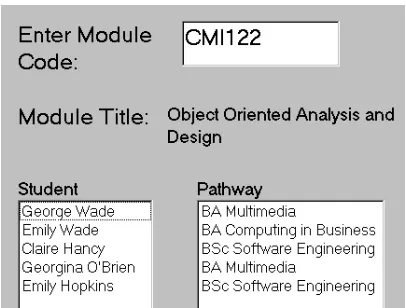
The process of developing software support for a use case is known as use case “realization”. As a simple illustrative example we will discuss how the “create class list” use case might be realized. First we agree a primary path for the use case, in this case we might identify the following steps: The user enters a module code into the system, the system displays the associated module title and the names of each student enrolled on the module along with their pathway (i.e. their named programme of study e.g. BSc Software Engineering). To support this primary path, the implemented system might include the screen shown in figure 2.
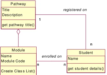
sequence diagram we might produce the initial UML class diagram shown in figure 4. The model indicates that a module is part of a pathway and that a student is registered on one pathway but may enrol upon many modules.
The class diagram is a modelling technique that runs through nearly all object-oriented methods. Cook and Daniels (1994) have described the type of class diagram depicted in figure 4 as representing an “essential” perspective. This means that the diagram represents the concepts in the domain under study. These concepts will naturally relate to the classes that implement them in software, but it is often not a direct mapping. Indeed the model is drawn with little or no regard for the software that might implement it, and is generally language independent. Later we might develop a class diagram related to this one from a “specification” perspective; in that perspective we are looking at software and the diagrams would not normally be comprehensible to users.
An essential class diagram can be used as an epistemological device during review meetings with stakeholders. Once the notation is understood the model can be used to identify inconsistencies and gaps while validating requirements. With reference to the model above we might consider questions such as: how do we model the fact that a module might be a mandatory part of one pathway and an optional part of a different pathway? And how do we represent the fact that undergraduate and postgraduate students cannot enrol on the same modules? And that students can only enrol on modules that are part of their pathway?
In our consultancy work we have experienced significant problems in conducting reviews based on object-oriented models such as class diagrams and sequence diagrams. These types of model are hard to understand for somebody unfamiliar with the underlying principles of object technology. Such models would normally be created by developers based on their personal perception and interpretation of the real-world situation. A stakeholder could interpret the situation differently but have difficulty translating their interpretation into the notation of the modeling language. The advantage of use cases in this context are their lack of object orientation and the fact that they are neutral to the implementation technology.
increased in size it became necessary to organize them in some way and we have done so by developing a simple use case repository in MS Access. Figure 5 represents the structure of our repository.
The classes in this model are implemented as tables in the database. It will be seen that the database structure accommodates the storage of images of screenshots and sequence diagrams. Thus the documentation of the “create class list” use case discussed above can be published as a database report. These reports can be produced in varying degrees of detail for a specific use case or for the set of use cases associated with a particular actor.
Our experience of asking students to document use cases using this repository has been that in practice use cases can be difficult to develop. Students are often uncertain about what to put in, or to leave out and how much of the system’s internal activity to include. It is not unusual to see use cases that are very clear about how the system needs to get and process data but don’t seem to capture business processes. This arises from the emphasis placed on designing the information system - not on designing the system supported by the information system.
There are situations in which there is a distinct lack of clarity about the nature of a problem situation and the use cases related to it. In the example presented above we considered use cases relating to attendance monitoring; the problem situation in which this takes place is complex: partly relating to our accountability to external bodies who provide funding for our students, partly concerned with our desire to identify students who might be experiencing difficulties with the course. In discussing these types of issue it is more natural to talk in terms of goals and business activities than use cases. For example if we assert the need to pursue a goal of “improving student retention rates by careful monitoring of student attendance” we expose the assertion to debate. Is this the best way to improve retention rates? What are the reasons for poor attendance? This type of discussion may lead to creation of an improved pastoral care service the activities of which might not be supported by a software system.
• Develop an expanded, flexible portfolio of courses. • Recruit, and retain, a greater number of students.
• Provide a caring and friendly culture supporting a stimulating and broadly-based
learning experience.
• Support participation in decision-making processes.
• Pursue excellence in teaching, scholarship and research.
When considering the implications these goals have for information systems design we were able to identify a number of use cases and a (larger) number of open-ended questions. For example the goal of developing more flexible courses implies the need for access to information about a student’s progress through an increasingly individualised programme of study. The use case “produce student progress report” would be important in this context but is also important to personal tutors who are trying to cultivate a “caring and friendly culture” in the context of “a greater number of students”. The identification of use cases to support a “stimulating and broadly-based learning experience” is more problematic and raises questions about the efficacy of IT-assisted teaching and learning in complementing conventional course delivery. We found that discussion of these types of issue often became very heated and inconclusive. The problems with our earliest meetings arose because they were held as brainstorming sessions in which participants were encouraged to pull use cases out of the air and argue about them. We subsequently found the application of SSM techniques to structure the deliberations did
encourage a more reflective and focussed consideration of issues leading to clearer conclusions.
Application of Soft Systems Methodology
The way in which SSM should be applied in different problem situations is discussed in detail in the key texts identified earlier. In the remainder of this section we provide a brief overview of the approach and an indication of how we have applied it.
student numbers. Some members of staff in the school had expressed the view that substantial development of the school’s intranet was the only way of addressing the problem with the resources available. In the initial stages of analysis we followed the SSM approach to exploring the problem situation through the development of mind maps and rich pictures to informally record and understand different views of stakeholders such as students, academics and
administrators. This background research included a study of 150 student assessments based on their experiences with the existing intranet. An extensive email debate was also recorded. During the interviews with module and pathway leaders the focus shifted to a discussion of a putative “student retention” problem. It was clear that the school would have to make every effort to support students through their chosen programmes of study and that our efforts to do so would be assessed in terms of the proportion of students successfully proceeding to graduation. Many views were expressed on this issue, some of them strongly held, but there was no consensus.
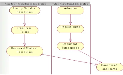
In keeping with the SSM approach we moved from identification of general issues of concern to the identification of relevant Human Activity Systems (HAS). The concept of a HAS is central to SSM. A relevant HAS is not an existing real-world system but a conceptual one related to an issue of concern. In order to clarify the nature of a particular HAS a “root definition” and “conceptual model” are created. Importantly these stages are carried out in the “systems world” and will be influenced by the application of “systems thinking” techniques. The root definition is a concise description which captures the essential nature of the HAS. For example we agreed the following root definition for a proposed “peer mentoring system”:
A system owned by the school that provides study skills support to students using
volunteers from more senior members of the student body with the quality of their
support activities monitored by academic staff
for the peer mentoring system. We have presented this conceptual model using the UML notation for activity diagrams, instead of the “cloud” notation used in the majority of SSM texts. This is a matter of personal preference, the notational differences are not significant and do not influence the semantics of the model.
When considering figure 6 in light of “systems thinking” criteria provided by SSM our attention was drawn to the question of how we would measure good and bad performance and what control actions should be taken in the event of poor performance. This and other questions led us into further development of the conceptual model and added structure to the debate.
The issues raised by the application of this type of thinking can be difficult to resolve. Discussion about how to monitor the effectiveness of introducing computer-based learning materials was particularly heated. We have agreed the following long-winded root definition:
The module delivery system is owned by both students and module leaders it is a vehicle
for the dissemination of teaching materials, but must also facilitate dialogues between
students and other students as well as students and staff. This will be facilitated with
discussion groups that provide assignment support, interactive teaching materials,
online feedback for modules. A steering group will be established, including student
representatives, to encourage the transfer of good practices in the development of
resources for one module to others. The system must enable students who miss key
lectures and/or tutorials through illness or other work commitments to “catch up”.
different mental models of what a core domain object actually is have profound implications for the design of the module delivery system.
We might expect that certain aspects of the activities in the conceptual model would be supported by a software system. To design this software system we need to extract use cases from the conceptual model. In figure 6, there is at least one activity that maps to an unambiguous use case – “book times and rooms”. Thus the conceptual model provides a baseline for understanding the wider role that use cases have in an organisational setting.
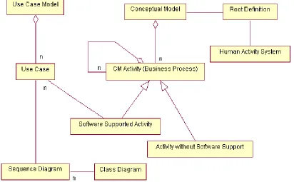
In considering these issues we have been pushed towards making a clear distinction between stakeholder goals, business activities and use cases. Figure 7 shows how our earlier repository model has been developed to support this distinction. The model suggests a hierarchy of business activities related to stakeholder goals that are taken to be the primary reasons for developing the system. The business activities would be represented in a hierarchy of conceptual models with the lowest models containing more primitive, elementary business activities than the higher ones. An individual business activity is represented in context in the image of the conceptual model of which it is a part. This model was particularly helpful during the development of the MaPPiT (Mapping the Placement Process with Information Technology) system in our school.
Many of our courses include a twelve-month industrial placement which needs to be carefully integrated into the curriculum. This is only possible when the placement is well-managed incorporating assignments that promote self-assessment and personal development. The MaPPiT system was developed to support this. We only provide a brief description of the system here, a more detailed account can be found in Downs and Lunn (2002) and on the MaPPiT website (www.hud.ac.uk/scom/mappit/).
MaPPiT is a software system developed to support a HAS defined by the following root definition:
A system owned by the placement unit to secure, develop and monitor rich learning
with their career aspirations; enhance their employability through experience in the
workplace; and increase their skills and knowledge, subsequently enabling higher levels
of achievement.
An initial conceptual model developed from this root definition included the following high-level activities:
• liaise with placement providers • prepare students for placement
• find and vet placements
• match students to placements • plan the placement programme
• monitor the placement
• help employers to supervise and appraise the placement
• equip students to reflect on and analyse the placement learning • assess/accredit the placement achievements
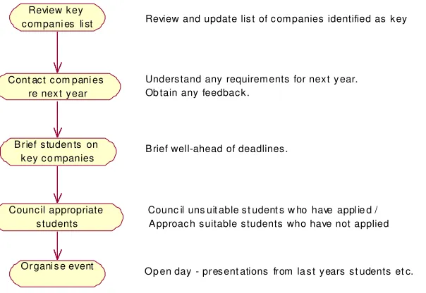
Each of these activities was then decomposed into a more detailed conceptual model containing more specific business activities in the hierarchical manner suggested by our repository model. For example the process “liaise with placement providers” is concerned with looking after liaison with key companies. Some companies will be key to the Placement Unit, and the unit will have a greater knowledge of these companies and what they are looking for. It is recommended that the unit should proactively seek suitable students for these companies in order to maintain the relationship with them. This process is represented as a conceptual model in figure 8.
web-enabled support developed in Lotus Domino. Complete documentation of the analysis and design of MaPPiT is available from the MaPPiT website.
Issues in documenting and supporting the proposed framework
In the examples presented above we have come close to prescribing a step-by-step procedure for converting relevant parts of root definitions and SSM conceptual models into use case models. Figure 9 communicates an idea of how this step-by-step process is currently conceived. Presented in this way the method seems prescriptive but this is not the intention. Figure 9 should be
interpreted as an SSM conceptual model. The appropriateness of this model should be discussed on a case-by-case basis. For example for each activity we should ask, with respect to a specific project or iteration within a project, the following questions: How will this activity help to meet the goals of this project/iteration? How will I assess the impact that this activity is having on the achievement of those goals? It is anticipated that the entire method would only be applied in situations characterised by uncertainty and confusion at the outset.
In an attempt to support our framework of techniques we have been developing a simple CASE tool that does not impose a specific step-by-step method. Figure 10 gives an idea of the principle abstractions that will be manipulated by the tool and how they are related. The model represents a development of the one presented earlier. The concept of an “iteration” is not represented in this model but we might expect the choice of iterations to be influenced by earlier identification of relevant HAS. For example software to support our “attendance monitoring system” could be developed in a single iteration. Development of software to support more complex HAS (such as the “industrial placement system”) would be accomplished through a series of closely related iterations.
conceptual and use case models in a diagrammatic form. In the immediate future we intend to develop the tool as an Add-In to Rational Rose (the most widely used CASE tool supporting the UML and USDP). This will involve using the Rose Extensibility Interface (REI) to provide links between our own diagram editors for the SSM models and UML models held in the Rose Repository.
In contemplating figure 9 some people may be concerned about the highly participative nature of our approach which can make it very time-consuming. It has been argued that web-based software systems should be developed in a software culture that is simpler, faster and more responsive to users than the one suggested here (Beck, 2000). The argument is concerned with our requirement for a large up-front commitment. In the full version of the method, stakeholders must engage in lengthy discussions based on SSM techniques and be interviewed by process experts who are able to develop formal use cases, from which the developer can produce UML class and collaboration models. The choice between unmanaged chaos and over-managed process is a long-standing one in software design. We argue that in situations such as the one discussed here, where the benefits of developing an intranet are unclear and possibly unquantifiable, linking the development process to fundamental business activities is self-evidently important.
SSM is perhaps best viewed as a disciplined approach to learning about the problem situation in which an intervention is to be made. It is hard to see how our approach could be applied without any learning taking place. We are an academic institution so the culture of our organisation is based on the belief that learning is generally beneficial.
Conclusion
avoids a consideration of system structure initially, this is in contrast to methods based on the UML.
This paper has reported on our work in developing a method to allow for the results of an SSM analysis to be incorporated into a requirements specification based on use cases. One of the main benefits arising from application of this method should be an improved user requirement definition for certain types of development project. This is an important pre-requisite to successful systems implementation.
References
Ackoff, Russel: (1972) On Purposeful Systems, Aldine Press, Chicago
Allen, P., Frost, S., (1998) Component-Based Development for Enterprise Systems: Applying the SELECT Perspective. John Wiley & Sons
Ashworth, C. and Goodland, M. (1990) SSADM: A practical approach. McGraw-Hill.
Ambler, S.W. (2002) Agile Modeling: Effective Practices for Extreme Programming and the Unified Process. John Wiley & Sons
Avison, D.E. and Wood-Harper A.T. (1990) Multiview: An exploration in Information Systems Development. Blackwell Scientific Publications.
Beck, K. (2000) eXtreme Programming Explained. Addison Wesley, 2000
Bustard, D. W., Dobbin, T. J., and Carey, B. N. (1996) “Integrating Soft Systems and Object-Oriented Analysis”, IEEE International Conference on Requirements
CCTA (1993) Applying Soft Systems Methodology to an SSADM Feasibility Study. HMSO, London.
Checkland, P. and Holwell, S.E. (1998) Information, Systems and Information Systems, Wiley, Chichester,
Checkland, P. (1981) Systems Thinking, Systems Practice, John Wiley & Sons, New York.
Checkland, P., and Scholes (1990) J, Soft Systems Methodology in Action, John Wiley & Sons, New York,
Coad P., et al (2002) Java Modeling In Color With UML: Enterprise Components and Process Prentice Hall
Cockburn A. (1997) Structuring use cases with Goals. Journal of Object Oriented Programming. Sep-Oct and Nov – Dec. SIGS Publications.
Cockburn A. (2001) Writing Effective use cases. Addison Wesley.
Cockburn, A. (2002) Agile Software Development. Addison Wesley Professional
Cook, S. and Daniels, J. (1994) Designing Object Systems: object-oriented modeling with Syntropy, Prentice Hall International.
Downs,D and Lunn, K. (2002) Analysis and Design for Process Support Systems using Goal-oriented Business Process Modelling, Workshop on Goal-Oriented Business Process Modeling (GBPM'02), Toronto (Canada), May 27- 28, 2002,
Fowler, M. and Scott, K., (2000) UML Distilled. Reading, M.A.: Addison-Wesley.
Highsmith, J. (2001) Agile Software Development Ecosystems. Wiley.
Jacobson, I. (1992) Object oriented software engineering: A use-case driven approach. Reading, MA.: Addison-Wesley.
Jacobson, I., Booch, G. and Rumbaugh, J. (1999) The Unified Software Development Process. Addison-Wesley.
Kaindl, H. (1998). Combining goals and functional requirements in a scenario based design process. Proc. HCI 98.
Keys, P. and Roberts, M.,(1991) Information Systems Development and Soft Systems Thinking: towards and improved methodology. In Systems Thinking in Europe, Plenum, London.
Krutchen, P. (2000). The Rational Unified Process – An Introduction. 2nd Edition. Addison-Wesley.
Lai, L.S. (2000) An integration of systems science methods and object oriented analysis for determining organisational information requirements. Systems Research and Behavioural Science 17, 205-228.
Miles, R., (1988) Combining “hard” and “soft” systems practice: grafting or embedding? Journal of Applied Systems Analysis 15 pp 55-60.
Miles, R., (1992) Combining “hard” and “soft” systems practice: grafting and embedding revisited. Systemist 14 (2) 62-66.
Mingers, J., (1988) Comparing conceptual models and data flow diagrams. The Computer Journal 31 (4) 376-379.
Mylopoulos, J., Chung, L., Nixon, B. (1992). Representing and using nonfunctional requirements: a process-oriented approach. IEEE Trans.Software Eng.18, 6, 483-497.
Prior, R., (1992) Linking SSM and IS development. Systemist 14 (3) 128-132.
Schneider and Winters (1998) Applying Use Cases: A Practical Guide. Addison Wesley.
Figures
P rint Clas s List
Enter A tt endanc e Data for Cl as s Tutorial
P rint A ttendanc e Rec ord for S pecific Clas s Mod ule Leader
[image:20.595.155.406.137.412.2]P rint A ttendanc e Record for S pec ific S tudent
[image:20.595.113.316.472.626.2]Figure 1 – Use Case Diagram for Attendance Monitoring System.
: Pathway
: Module : Student
Create Class List Form
CreateClassList( )
getStudentDetails( )
[image:21.595.132.502.76.244.2]getPathwayTitle( )
Figure 3 – Sequence Diagram for “Create Class List”
M odule Nam e M odul e Code
Create C las s Li st()
S tudent Name
get s tu dent detai ls ()
n n
n n
enrolled on P athway
Title Des c ription
get pathway title() 1
n n 1
regis tered on
[image:21.595.122.309.303.435.2]A c tor Nam e Des c ription
Us e Cas e Des cription
Frequenc y of E x ec ution P re-Conditions
P os t-Conditions n
n n
n
P rim ary P ath Desc ription of B as ic Flow S equenc e Diagram (im age)
A lternative S tep
Desc ription
S c reenshot (im age)
S tep
Desc ription
S c reenshot (im age) n
n
[image:22.595.124.381.82.364.2]n n
Figure 5 – Class diagram for our Use Case repository
[image:22.595.114.524.421.671.2]Use Case Business Activity
Name Description
Conceptual Model (image)
n n n n n n Goal
Priority (Low, Medium, High) Description n n n n Stakeholder Name
[image:23.595.133.511.77.268.2]Description nn nn
Figure 7 – Extensions to the repository model
Review k ey c om pani es li st
Cont ac t c om pani es re nex t y ear
B rief s tuden ts on k ey c o mpanies
Counc il appropriate s tudents
Or gani s e event
Review and update lis t of c om panies identified as k ey
Unders tand any requirem ents for nex t y ear. Ob tain any feedbac k .
B rief well-ahead of deadlines .
Counc il uns uit able s t udent s w ho have appl ie d / A pproac h s uitable s tudents who have not applied
Op en day - pres ent ations from la s t y ears s t udents et c.
[image:23.595.144.446.335.543.2]A im s
+ E x plore the problem s ituation
+ Rec ord and unders tand different views of people
+ Develop c learer pic tures of the situation and factors that influenc e the s ituation.
+ Determ ine the difference between what is c onc eptually des irable and how that differs from what c an be done within the c ulture (what is culturally feas ible).
Tools / Tec hni ques / Methods
+ Interviews with the ac tors , p roblem owners , c l ients a nd other s tak eholders + Obs ervation of organis ational ac tivities , behaviours and proces s es + Col lecti on of s ec ondary data
+ B rains torm ing + Root Definitions (RDs)
O utc o mes
+ Ric h pic tures /m ind m aps repres enting s tak eholders / k ey play ers views + A n im proved unders tanding of the problem s ituation
+ Conc eptual m odels of des ired future s y s tem s (and s ub-s y s tem s ) as des c ribed in the root defin itions
D efine the P roble m S ituation: Uns truc tured
Ex pres s th e P roblem S ituation
Identify Relevant Hum an A c tivity S y s tem s (HA S ) and c ons truc t Root Definitions for these
B uil d Concep tual M odel for eac h HA S
A naly s e Conc eptual M odel and identify Candidate Us e Cas es
Doc um ent prim ary and alternative p aths fo r each Us e Cas es
Develop Collaboration Diagr ams for eac h Us e Cas e
Develop Clas s Diagram c ons is tent with full s et of Collaboration Diagram s
A im s
+ Identify use c as es in term s of us er goals and bus ines s proc es s es + M ap us e c ases to an iterative developm ent plan for propos ed s oftware s y s tem + Develop objec t c ollaboration from use c as es
[image:24.595.134.504.89.407.2]+ M odel objec t c ol laboration us ing UM L s equenc e di agram s + Cros s c hec k between s equenc e diagram s and UM L c las s diagram
Figure 9 – Conceptual model for the proposed development method
[image:24.595.116.528.463.718.2]