2016 Joint International Conference on Artificial Intelligence and Computer Engineering (AICE 2016) and International Conference on Network and Communication Security (NCS 2016)
ISBN: 978-1-60595-362-5
An Intelligent NIC Solution Based on T4240 Processor
Xin SONG
School of Electronic and Information Engineering Tianjin Vocational Institute Tianjin, 300410, China [email protected]
Keywords: INIC, SR-IOV, NFV, SDN, Open VSwitch, Virtual Machine.
Abstract. Intelligent network interface cards are used throughout the servers deployed in compute,
storage and network infrastructure. This paper presents an intelligent NIC solution based on Freescale T4240 processor. It is a low profile PCI Express card with 4 SFP+ ports, up to 128 virtual network interface and integrates standard NIC, SR-IOV, virtual switch functions. Moreover, it can not only offload TCP segment, IP fragment, QoS, filtering, but also route and bridge the data packets between the virtual machine and virtual machine, virtual machine and physical network, physical network and physical network. The solutions can be widely used in new cloud computing data centers that need to deploy SDN and NFV to reduce costs, increase network flexibility, scalability and reliability
Introduction
As cloud computing continues to drive investment in networking, data center infrastructure with network virtualization applications is becoming the fastest growing markets. Cloud service providers are using virtualization technologies such as network function virtualization (NFV) and software defined networking (SDN) to reduce costs, while increasing network flexibility, scalability and reliability. Open vSwitch (OVS) is an open source virtual switch providing Virtual Networking services in the NFV and SDN [1]. It provides network connectivity from Virtual Machines (VMs) to the physical network and between Virtual Machines.
[image:1.612.222.386.457.682.2]
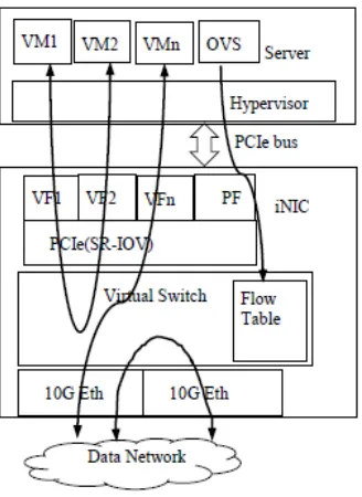
Figure 1. Typical iNIC Deployment.
fourth core to manage the creation and operation of virtual machines (VMs). The paper presents an intelligent NICs (iNIC) solution, which integrate standard NIC function, PCIe Single Root I/O Virtualization (SR-IOV) and virtual switch functions. SR-IOV allows the server to separate access to the physical network among the physical function (PF) and the virtual function (VF). This iNIC offloads all the switch functions to their own processor, freeing up those cores for other uses.
A typical iNIC deployment is shown in Fig. 1. A Powerful computer is used to provide cloud service. Only one core is reserved to run OVS controller to configure iNIC vSwitch via PF and flow table. Other cores can be used to run VM for various customized services. Each VM is assigned a VF which enables network traffic to bypass the server’s software switch layer of hypervisor and achieves higher performance. Server’s OVS actually only contains control plane. Accordingly, iNIC’s virtual switch is a data forwarding plane and supports three kinds of traffic flow VM to VM, VM to Ethernet and Ethernet to Ethernet.
Hardware Design
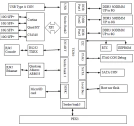
[image:2.612.179.447.415.667.2]The iNIC’s hardware function units is shown in Fig. 2. The main chip is T4240 processor, which combines 12 dual threaded e6500 cores for a total of 24 threads with high performance data path acceleration logic and network and peripheral bus interfaces [2]. The three fully programmable DDR SDRAM controllers supports DDR3 memories up to 3x8G size. The serialization/deserialization (Serdes) is for high speed serial interfaces. Serdes bank1 and bank2 is used for network protocol. Cortina Quad HY CS4340 is selected as PHY connected to Serdes bank2 and provides 4x10G SFP+ port. 128M nor flash is used to store uboot, Linux kernel, root file system and virtual switch application which is connected to local bus. T4240 contains 4 PCI Express controllers (PEX), which can be configured to operate as either a PCI Express root complex (RC) or endpoint (EP) device. The third PCIe controller supports SR-IOV with up to 128 VFs, thus the iNIC can supports up to 128VMs. PEX3 is assigned 8 lanes achieving 40Gbps bandwidth. Other PEX works in RC mode.
Figure 2. INIC Block Diagram.
processor cores, network interfaces, and hardware accelerators in a multicore SoC [3]. BMan primary function is to reduce the overhead on software for managing free buffer pools for multiple hardware modules via managing pools of data storage buffers and the acquisition and release of these buffers on behalf of multiple processor cores, network interfaces, and hardware accelerators. FMan is a functional unit that combines the Ethernet network interfaces with packet distribution logic to provide intelligent distribution and queuing decisions for incoming traffic at line rate. The DPAA significantly reduces software overheads associated with high touch, packet forwarding operations.
Other units such as SATA controller, USB controller and PEX can extend iNIC functionality. For example, inserting hard disk to SATA allows iNIC to provide network attached storage server. Inserting a crypto chip to a PEX allows iNIC offload encryption and decryption
Software Design
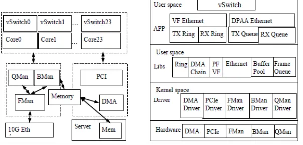
INIC application is a multiple threads in user space. Software Architecture is shown in Fig. 3, which can be divided into 3 major blocks Virtual Switch, DPAA Ethernet and VF Ethernet. They are indicated by the dashed line box. From the point of the level, iNIC software is divided to three layers hardware drivers, libs and apps which is shown in Fig. 4. Hardware driver layer is located in kernel space including the driver of the main hardware such as DMA, PCIe, FMan, BMan, QMan. The libs layer is in user space, wraps the driver functionality and provides application programming interface. The top layer is APP including VF Ethernet, DPAA Ethernet and vSwitch. Both Ethernets will register the RX and TX callback function to the vSwitch application.
VSwitch Design
VSwitch is the multiple threads, user space service program and integrates OVS data plane code and DPAA. T4240 need to change Make file using the PowerPC64 toolchain. This will make sure that iNIC is compatible with OVS control plane run in the serve. It is responsible for parsing packet header and processing/forwarding according to the Flow Table configured by the remote OVS control plane. It also manages QoS, filtering, offload functions. Each core will run a separated vSwitch thread. There is no resource shared among the cores except the Flow Table, but Flow Table is read only for vSwitch, so all the vSwitch threads are completely parallel, and the lock-free design improves performance.
[image:3.612.158.460.473.618.2]
Figure 3. iNIC Software Architecture. Figure 4. iNIC Software Layer.
VF Ethernet Design
bytes). The ring and BD contents are shared between the VM the iNIC. When transmitting the packets, VM Ethernet driver will update the BD and increase consumer index. The VF Ethernet TX function will check the ring index update and parse the corresponding BD, accurate the packet address and length, then call DMA to copy the data from server memory to the iNIC memory, finally push this packet to vSwitch for further processing.
USDPAA Ethernet Design
DPAA Ethernet block includes the driver of QMan, BMan and FMan. User space processes access QMan/BMan using software portals that are dedicated to user space. A user space process opens such a device and requests that the device be mapped directly into the process's address space. FMan is a hardware accelerator responsible for preprocessing and moving packets into and out of the data path. Usually, the main Rx flow follows these steps: packets are received from one of the Ethernet MACs, are temporarily stored in the FMan internal memory, and then delivered to SoC memory via the FMan DMA. The packet header (max size 256 bytes) is stored and the modules common database structure is allocated. Then the packet is parsed by the parser or by the FMan controller. According to parsing results a key may be extracted by KeyGen, a destination frame queue ID may be set, the packet may be classified by the FMan controller. In that stage, some offloads may be done like reassembly, fragmentation, header manipulation and frame replication. At the end of the classification and manipulations stage, the packet may be colored by policer. At the end of this process, packets are delivered to SoC memory via the FMan DMA and then are enqueued to a frame queue or dropped. The processing order is Parse-Classify-Distribute (PCD) flow dependent, based on user configurations. Each step is depends on previous state results. This structure enables flexibility, which efficiently supports many flows. On Tx the frames are transmitted via the desired MAC with optional checksum generation.
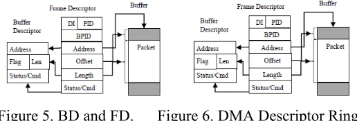
The Frame Descriptor (FD) is the basic element that is queued by the QMan. Fig. 5 shows the layout of this data structure. All the packets through the DPAA Ethernet must be descripted by FD. If walking through the VF Ethernet, the packets should be descripted by BD. The vSwitch is responsible for the converting BD and FD according to destination.
PCIe Design
PCIe driver in the kernel space is to provide the interface for access the controller register. PF/VF library initializes controller to enable VFs and PFs; configures the inbound windows, outbound windows, MSI-X trap window. Each function will be assigned different 64G outbound space for IOMMU support, so the VM’s memory cannot be greater than 64G. Up to 8 MSI-X interrupts can be triggered and shared by the 24 rings. PCIe endpoint exposes the local resources through BARs to the host side with inbound memories:
BAR0: 16MB size to map CCSR
BAR1: 8KB size to store MSI-X table and peddling table. BAR2: 256kB size to store Ring Descriptor and 521 BD entries.
Ring Design
Ring is used by the DMA, VF Ethernet, vSwitch. So the solution abstracts the common ring functions to develop a Ring library. Each ring has three index: head index, current index, tail index. DMA descriptor ring, Ethernet TX ring, RX ring are all the instance of ring. Fig. 6 shows the ring example of DMA.
DMA Design
DMA channel works in chain mode. The drive will create the list of DMA descriptor (DD) then set the last DD address to the DMA channel register. The DMA will load and parse the descriptor and then start the transfer. The detailed processing is as follows:
1. Build link descriptor segments in memory.
2. Poll the channel state to confirm that the specific DMA channel is idle. 3. Initialize CLNDARn to point to the first link descriptor in memory.
4. Clear the mode register channel transfer mode bit to indicate basic chaining mode. 5. Clear and then set the mode register channel start bit, start the DMA transfer.
DMA descriptor list is a ring instance. The working flow is shown in the Fig. 6. The DDs between the HEAD and TAIL index are idle and wait to use. The DDs between the TAIL and CURRENT index indicate the data has been transmitted and is ready to free. The DDs between the CURRENT and TAIL index mean that the data information has been update to descriptor. DMA channel will automatically load them and start the traffic.
[image:5.612.176.434.273.361.2]DMA chain library not only provides the interface for Ethernet to update the descriptor but also call the callback function to notify the transfer has been done.
Figure 5. BD and FD. Figure 6. DMA Descriptor Ring.
DMA Memory Design
Because iNIC application run in the user space, it is hard to convert virtual address to the physical address. But the hardware such as DMA, BMan needs the physical address not virtual address. So the solution provides a way to resolve this issue. A large memory region is reserved for the iNIC DMA memory when kernel initialize the memory and TLB1 will be created. Access the DMA memory will not encounter the page miss issue, which can improve the performance. The DMA memory is mainly used by Buffer Pool library to create a large number of buffers for the Ethernet to store the data packets.
Conclusion
Using T4240 powerful processing capabilities and architecture of the DPAA, the iNIC can achieve high network performance. Regarding 1518 bytes, the throughput between the DPAA Ethernet can reach 40Gbps. The throughput of VM to VM can reach 10Gbps. This iNIC supports 4 10G Ethernet and up to 128 VMs. It not only can be used as a SR-IOV network interface card, but also can be used as a network switch. More importantly, the iNIC provides the Virtual Switch implemented based on standard OVS, integrating the NIC and OVS server. It is easier to use, and more flexible and reliable. It is better suited to NFV or SDN network and can be will greatly reduce the data network deployment costs.
References
[1]Open Vswitch for NFV https://wiki.opnfv.org/open_vswitch_for_nfv.
[2]T4240 QorIQ Integrated Multicore Communications Processor Family Reference Manual, NXP Semiconductors, 2014.