© 2016, IRJET | Impact Factor value: 4.45 | ISO 9001:2008 Certified Journal | Page 137
Amphibious Vehicle
Prof.Anup M.Gawande
1, Mr.Akshay P. Mali
2,
1 Asst. Prof. Mechanical Engg Dept, STC SERT, Khamgaon, Maharashtra, India
2UG Student of Mechanical Engg, STC SERT ,Khamgaon, Maharashtra, India
...**...
Abstract-
An Amphibious vehicle is a means of transport, viable on land as well as on water even under water. It is simplymay also called as Amphibian. Amphibious vehicle is a concept of vehicle having versatile usage. It can be putforward for the commercialization purpose with respect to various applications like in the field of military andrescue operations. Researchers are working on amphibious vehicle with capability to run in adverse conditionsin efficient way. This paper focuses on concept of amphibious vehicle in detail. In later stage of paper we haveexplain and described the design and analysis of amphibious car. We have followed proper design procedureand enlisted the material used in detail. Capabilities of efficient amphibious vehicle will fulfil all the emergingneeds of society. Success of every concept largely relies on research and development, though amphibiousvehicle is yet to travel a long journey of innovative development, it has shown excellent potentials for futurebenefits.
Introduction
Vehicle design is one of the important aspects for the performance of a vehicle. When the vehicle across amedium at high speed, the medium will acts on the vehicle in term of resistance [1]. Air is one of the medium ofspace that provide resistance when vehicle travelling at high speed due to air space densities. This contributes to
the consumption of fuel use of for vehicles. Besides that, the design of the vehicle should have an aura ofattraction to people who see every details of design in terms of creativity and aesthetical value. Therefore, in thispaper designs process are documented according to stage which the design is start from scratch. Selection ofmaterials for the manufacture of basic materials is an important vehicle for ensuring that the vehicle is able tofloat on the water [2]. Among the criteria required material for manufacture of the vehicle is that it
must bedurable, has good properties of waterproof, easy to set up and easy to do the repairs in the event of damage and
maintenance work.
Need of Amphibious Vehicle
About 75% of Earth‘s surface is covered by water. A vehicle that could travel on land and water couldpotentially change current transportation model. Transportation on land is very common but on the other hand
water ways are naturally available but are not considerably used relatively, and here the Amphibian vehicles areproved to be beneficial.
LITERATURE SURVEY
4.1 Amphibious Vehicle
There are not many vehicles of this type used in daily use. Only some vehicles are used and that are used in military. Some of them are as follows.
4.2 Amphibious Cycles
An Amphibious Cycleis capable of operation on both
© 2016, IRJET | Impact Factor value: 4.45 | ISO 9001:2008 Certified Journal | Page 138 recumbent frame with separate floats, and is
propelled using a paddle wheel. A speed test on water achieved an average speed of 1.12 m/s. The cyclist was able to transition the cycle both into and out of the water unassisted. This elegant prototype has a real application in urban areas of flooding, as well as applications in the leisure industry [5].
Amphibious buses
Amphibious buses are employed in some locations as a tourist attraction. A recent design is the AmphiCoach GTS-1.
Construction and Working
The Amphibian car consists of following part:-TubeThe tube is located at the bottom side of the car frame or chassis. It has two valves are provided, one is to fillthe air in tube and the other is for outlet valve to exhaust the air. When we want the car to run on the water thenair filler machine is started for the filling the air in tube. Thus the tube is filled by air which will help the car tofloat on water and also carry the weight of car. Thus the tube serves the function that it help to float the car onwater. The tube is manufacture of some special material which will not puncture easily.
There are two blades (fans) each of them having four plates used in amphibian car. These are circular in shapewith some inclination. The diameter of the blades is slightly less than that of diameter of wheel, as the car hasthe front engine
rear wheel drive (frwd) the blades fitted on the rear axle which will propel the car on the water.
It serves the function to give motion like wheel, on water surface.Compressor (air filler)As its name indicates it serves as the function to fill the air in the tube with high pressure and instantly. Itdoesn‘t require fuel to work. The machine is connected to the battery. This machine requires the d c voltage of12 volt. It is fitted in car body.
Motor
The motor transmits the power to rear axle with the help of bevel gear arrangement to transmit the power in 90º
from motor to rear axle. The range of power required to it is 12v. The motor will run with the help of battery
supply. (In model the motor will serve as the function of engine).
Battery
The battery used in the car is of 12v, 3.5amp. The battery is used to supply the power to air filler machine, motorand other equipments or accessories like head light, tail lamps and horns. It supplies dc current to the motor which requires 12v dc supply and also to the air filler machine.
Transformer
Transformer is used to reduce the ac power supply and charge the battery. It is fitted in the car body to charge the
© 2016, IRJET | Impact Factor value: 4.45 | ISO 9001:2008 Certified Journal | Page 139 In our model of amphicar, we have used a wiper
motor which is connected to the D.C. supply battery asan engine. The engine rotates the driver shaft and so the bevel gear rotates and due to which the power
is transmitted from engine to rear shaft. As the rear shaft rotates the blades assembled on it also rotatewith rear axle speed, thus the blades propels the vehicle in forward direction.
Materials Used
System design
System design mainly concerns with various physical constrains, deciding basics working principles, space requirement, arrangement of various component etc. Following parameters are look upon in system design [8, 9] Selection of system based on physical constrains. The mechanical design has directs norms withthe system design hence system is designed such that distinctions and dimensions thus obtain inmechanical design can be well fitted in to it. Arrangement of various components made simple
to utilized every possible space. Ease of maintenance and servicing achieved means of simplified lay out that enables quickdecision assembly of component.
Scope of future improvement.
System design
System design mainly concerns with various physical constrains, deciding basics working principles, space requirement, arrangement of various component etc. Following parameters are look upon in system design [8, 9]
Selection of system based on physical constrains. The mechanical design has directs norms with the system design hence system is designed such that distinctions and dimensions thus obtain in mechanical design can be well fitted in to it.
Arrangement of various components made simple to utilized every possible space.
Ease of maintenance and servicing achieved means of simplified lay out that enables quick decision assembly of component.
Scope of future improvement.
Design process
The design stage process of UTeM’s AHV body is shown in Figure 1. The early stage of the design process is to create a conceptualization idea. Creativity is required to generate the ideas during the conceptualization stage. Brainstorming
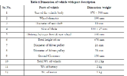
[image:3.595.39.249.98.223.2]approach is used to produce as many ideas that are relevant for the AHV specification as described in Table 1.
© 2016, IRJET | Impact Factor value: 4.45 | ISO 9001:2008 Certified Journal | Page 140 process and several concepts are feasible to
proceed to conceptual designs while the irrelevant ideas are eliminated. Once the conceptual design is finalized, the Pugh’s selection method is employed to conduct the analysis. The Pugh’s selection and assessment are evaluated by summation of ‘+’ and ‘-‘that indicate the element present in the criteria. The ‘+’ will be multiplied by weigh that been assessed for every criteria before been total up and the result is presented in Table 2 using Pugh method. There are eight criteria to be concerned to evaluate the best selection for the concept design.
Fabrication process
Fabrication process for the body of AHV is very crucial stage since all processes are executed manually and conventionally. Therefore, the most important aspect in fabrication process is to produce a good bodywork that meet the specifications and identical as possible to the design selected generate in CAD. The limitation in this process is to strictly follow the design specifications for the body of amphibious vehicle. The fabrication flow process for the body contains of several stages and it is shown in figure 4 below.
Molding process is the most important stage where at this stage the quality of mold will influence the end product of the quality. A good quality of mold will quicker the time forsurface finishing. The mold is made up from plywood which is use as a bone of the mold. Polystyrene is then applied to fill the empty space in the molding body. Wall filler will be used to fill pores of the molding surface and it will be sanding using sand paper to refine the surface finishing of mold.
Figure 5: Molding process
As the mould is completed, the glass fiber which is from chop strand mat and woven fabrics are used to fabricate the body by using hand layup technique. Figure 6 show the process of hand layup techniques. A release agent, liquid of wax form will be applied onto the mold. This allowed th finished product to be removed cleanly from the moldwithout any sticking problem that will affect the finished product quality. After the release agent have been applied to the entire surface mold, resin mixture which is consisting of polyester resin, epoxy type of resin is mixed together with its hardener and applied to the surface of the mold. Sheets of fibreglass cloth are cuts and lay onto the mold, and then more resin mixture is added using brush a brush or roller. It is important to ensure that no air is trapped between the fiberglass clothed and mold and roller is used to remove the air pockets by pushing out the air pockets away from the fiberglass layer. Air pockets will cause fibreglass strength weaker. To add more layer of fiberglass, additional resin is applied and possibly sheets of fiberglass cloth also applied onto it. To make sure the resin is saturates evenly and air pockets are removed, hand pressure and roller are used. The work is executed quickly enough to complete the job before resin starts to cure, unless high temperature resins are which will not cure until the part is warmed.
© 2016, IRJET | Impact Factor value: 4.45 | ISO 9001:2008 Certified Journal | Page 141 Next, demolding process is executed to separate the
product and mold. Demolding process must be done carefully to avoid defects in the product. The next process is the surface finishing stage. Car body filler putty and sand paper is used to gain smooth and continuous surface finishing. The final finishing can be observed in Figure
Figure 7: Surface finishing of the Bodywork
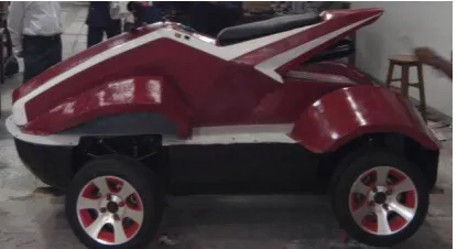
Lastly, the body undergoes painting process and it was assembled to the chassis by using bolt and nut. Marine seale applied to the area which is exposed openly and has gap between the surface to avoid leaking or water entering the body of the vehicle which can leads to additional weight problem to vehicle. The final product of the UTeM’s
[image:5.595.39.245.190.343.2]Amphibious Hybrid Vehicle is shown in Figure
Figure 8: Shows the final bodywork for the UTeM’s
AHV.
Conclusion
The development of body for amphibious is carried out based on the technical specification information required. The process started from the design selection stage and completed with the fabrication process of the bodywork. The AHV composite bodywork produced using fiberglass suit the AHV
capability to work on both the ground and water surface.
References
[1] McBeath, S. and Rouke, Brian, “Competition Car Composites, A Practical Book”, Haynes Publishing, (2000).
[2] Savitsky D. and Brown P. W., “Procedures for hydrodynamic evaluation of planning hulls in smooth and rough water”, Marine Technology, Vol. 13, No. 4, October, pp.381-400, (1976).
[3] Neewey, C., and Weaver, G. (ed), “Materials Principles and Practice”, Butterworth Scientific, (1990).
[4] Multi Sport Composite, “A Practical Guide to Composites”, Multi Sport Composite Ltd, (1995).
[image:5.595.38.246.497.610.2]