© 2016, IRJET | Impact Factor value: 4.45 | ISO 9001:2008 Certified Journal | Page 2626
DEVELOPMENT OF DIE FOR THE PRODUCTION OF PLASTIC CONTAINER
Abhishek Sawalkar
1, Ashish Yelekar
2, Yogesh Yadav
3, Aakash Bisen
4JD College of Engineering And Management, Nagpur, India. Department of Mechanical Engineering, Student1,2,3,4
---***---Abstract
The purpose of this project is to understand the development of die for the injection moulding machine. The injection moulding is one of the popular manufacturing process amongst the existing processes in which the parts are produced by injecting material into mould. The materials used mainly for injecting into the mould are thermoplastic and thermosetting polymers. This method helps to produce any intricate product easily and precisely. For generation of designed product needs to convert the product design into core and cavity of die. The die development is done by using CAD/CAM software’s and advanced machines which develop die easily and in stipulated time. The die development goes in various stages and machining operations.
Keywords-
plastic injection moulding, mould, thermoplastic, CAD, CAM, shot capacity.1. Introduction
Injection moulding is a manufacturing technique for making parts from plastic material in production. Molten plastic is injected at high pressure into a mould which is the inverse of the products shape. Injection moulding is widely used for manufacturing a variety of parts from smallest compared to entire body panels of cars. Injection moulding also known as presses holds the moulds in which the components are shaped. The clamping force applied by this machine is 800KN.This amount of force is needed to close the mould during injection process. An injection mould or die is an arrangement if metal parts in one assembly. It has one or several cavity spaces built in it to the plastic product shape. Molten plastic is injected into the cavity/cavities to form the plastic products.
1. Mould
Mould is the common terms used to describe the tooling used to produce plastic parts in moulding. It’s usually only used in mass production where thousands of parts were being produced.
The mould’s function has divided into five parts there are: 1. Receive the molten plastic
The mould will ready to receive the molten plastic and the opening will allow the molten plastic flow into the mould cavity. 2. Distribute the molten plastic
After the molten plastic flow into the mould the molten plastic will distribute by gate system of the mould. 3. Form and shape the plastic product
Through the gate system the molten plastic will fill up the cavity of mould and ready to form and take shape of the product in the cavity of mould.
4. Cool the moulded product
After the cavity has been filling up with the molten plastic the cooling system gets activated and it solidifies the molten plastic. 5. Eject the moulded product
After few seconds the plastic is reach the solid stage and the plastic product will be eject by the ejection system of the mould from the mould.
The mould is consisting of two main parts.
© 2016, IRJET | Impact Factor value: 4.45 | ISO 9001:2008 Certified Journal | Page 2627
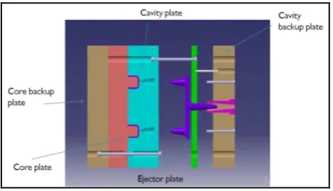
Fig 1. Basic injection mould structureMoulds are typically constructed from hardened steel, pre hardened steel, aluminium but in our project we have used tool steel P20 pre hardened as a mould material .The mould used in mass production where thousands of parts were being produced. The choice of material to build a mould is primarily one of economics. Steel moulds generally cost more to construct but their longer lifespan will offset the higher initial cost. Tool steel P20 is having higher life and good surface finish which offset the initial cost of this material. The mould is making by using the VMC (Vertical Milling Centre), EDM (Electrical Discharge Machining), CNC (COMPUTER NUMERICAL CONTROL) machine.
2. Design
The design of mould is a very important point in mould making. There are so many factors that we have to consider during the designing of mould but in our project we put emphasis on number of cavities in the mould. The following points are responsible for number of cavities.
A. Shot capacity
It is the capacity of machine which means the amount of resin required to fill the sprue, runner and cavity of mould. Method to find number of cavities from shot capacity:
Formula:
a. Shot capacity (w) = swept volume × µ × c
Where,
µ = density of plastic at normal temperature c = 0.35 for crystalline plastics
c = 0.95 for amorphous plastics
Shot capacity (w) =... (gm)
b. Determination of number of cavities by shot capacity
Based on 85% of rated shot capacity
Number of cavities by shot capacity (Ns) = 0.85 × w/m
Where,
w = shot capacity m = mass of component Number of cavities (Ns) =...
© 2016, IRJET | Impact Factor value: 4.45 | ISO 9001:2008 Certified Journal | Page 2628
B. Plasticizing capacity
The injection machine plasticizing capacity is also a factor. Divide the plasticizing capacity (P) OF the machine by the estimated number of shots per minute(X) and part weight (W).The relation is below:
NC=P/X×W
C. Clamping capacity
The clamping force required to keep the mould closed during injection. Clamping force must exceed the force given by the product of injection pressure and projected area of all impressions, runners and gate.
[image:3.595.204.396.214.310.2]
Fig 2. Designed cavity and core part in CREO software
After designing the parts of mould in CREO software the designed file is transfer to power MILL of DELCAM software where we can check machining is possible or not.
3. Machining
The file, once reaches to the power MILL software of DELCAM (is CAD/CAM as well as manufacturing software), it helps to produce CAM solution for the programming of tool paths for two to five axis VMC and CNC machines. As we are using VMC machine for the machining of mould the DELCAM software will generate the NC programming and process plan as per the design of mould for VMC machine.
[image:3.595.202.394.440.539.2]
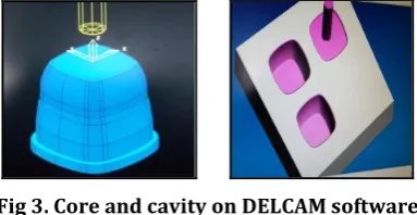
Fig 3. Core and cavity on DELCAM software
All we need is to provide some data like feed, depth of cut, rpm (rotations per minute), type of tool required and tool specifications. The NC programming’s are then transfer to VMC machine and copy the programme to the control system of the machine. The mould fabrication processes will be carried out using various type of machining process.
The various processes required for development of mould are:
A. Center adjustment:
This process is very important. We have to repeat this process every time when we do different type of machining process like roughing, drilling. In the centre adjustment by using dial gauge on VMC machine the centre of raw material is calculate.
© 2016, IRJET | Impact Factor value: 4.45 | ISO 9001:2008 Certified Journal | Page 2629
B. Center drilling and drilling operation:
The purpose of center drilling is to drill a hole that will act as a guide for drilling the final hole. The hole is only drilled part way into the work piece because it is only used to guide the beginning of next drilling process. For doing center drilling small diameter of tool has taken and then goes for drilling operation by using bigger drilling tool. Drilling is the operation of producing a cylindrical hole of required diameters and depth by removing metal by the rotating edge of a cutting tool called drill. Drilling is simplest method for producing a hole. The size of hole made by drilling may not be accurate and the internal surface will not be smooth due to which after drilling operation reaming is necessary for sizing and finishing a hole.
Fig 5. Drill bit
C. Roughing:
It is the machining process of using rotary cutters to remove material from a work piece advancing in a direction at an angle with the axis of the tool. The roughing is done on VMC machine. The cutter of roughing is moved perpendicular to its axis that cutting occurs on the circumference of the cutter. As the cutter enters the work piece, the cutting edges of the tool repeatedly cut into and exit from the material, shaving off chips from work piece with each pass. The tool used in roughing is insertable.
[image:4.595.253.346.355.471.2]
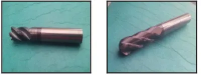
Fig 6.insertable tool
D.
Engraving process:
[image:4.595.221.367.572.610.2]Engraving is the practice of incising a design onto a hard, usually flat surface, by cutting grooves in to it. Dies used in mass production of moulded parts are sometimes engraved to add special touches or certain information such as part numbers. Steel engraving is the same technique on steel or steel-faced plates, and is used on cavity, so that it comes on the back side of product.
Fig 7.Engraving tool (burins)
E. Finishing:
© 2016, IRJET | Impact Factor value: 4.45 | ISO 9001:2008 Certified Journal | Page 2630
[image:5.595.199.399.98.173.2]
Fig 8. Endmill tool and Ballnose tool
The endmill tool is used where flat surface is present. The ballnose tool is used where rounded portion is present.
4. Super finishing
As the surface of mould has a direct impact on the surface of product being moulded. So proper super finishing is essential. There are some methods to do super finishing and get the product with good surface finished.
a. Stoning process:
The stones are used for clearing out the flaws by manually. They have different numbers of stones like 120,220 to 400.In our project we have used 220 number stone as it is cheaper and have good capability to remove the flaws.
[image:5.595.241.351.341.430.2]
Fig 9. Stoning process
Paste is used as an abrasive material to give the excellent surface finish.
b. Final finishing process:
In this some scrap papers have used by the machine to give the excellent surface finish of core and the cavity. Similarly the diamond finish.
Like in stoning, the papers and diamond paste also having the qualities according to the number assign to them. In scrap papers 220 to 400 number scrap papers available and diamond 10-20, 4-8, 0-2. This depends upon the size of material of grains in paste.
Fig 10. Polishing Process
5. Conclusion:
© 2016, IRJET | Impact Factor value: 4.45 | ISO 9001:2008 Certified Journal | Page 2631
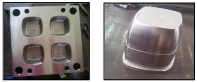
Fig 11.cavity and core after machining process
7. References
[1] RGW RAI (4th edition), injection moulding die design part 1.affiliated east-west pvt, 2014 [2] Martin Schuster (2005), mold making in 3-d, mold making technology, vol. 0.2/05, pp-21-22.
[3]Song Bin et. Al. (2003), a design methodology for compressing lead time from plastic part design to mould making. International journal of CAD/CAM, vol. 03, no. 02, pp. 43-50.
[4] Typical die casting machine http:\\ www.evergreatmc.com