© 2016, IRJET ISO 9001:2008 Certified Journal Page 2870
Experimental Analysis of Natural Convection Heat Transfer from
Horizontal Rectangular Fin Arrays with a Semi Circular Profiled Notch
at the Center
Vishal Hegana
1, P.R. Kulkarni
21P.G. Student, Department of Mechanical Engineering, Dr. J.J. Magdum College of Engineering, Jaysingpur,
Maharashtra, India
2Associate Professor, Department of Mechanical Engineering, Dr. J.J. Magdum College of Engineering, Jaysingpur,
Maharashtra, India
---***---Abstract -
A systematic experimental investigation of the fin spacing for the given fin height, fin length, for the width of array and heat input on natural convection heat transfer from horizontal fin array was carried out. A horizontal rectangular fin array with aluminum fin and aluminum spacer is constructed in which the distances between the fins are varied with adding or removing the spacers of different thickness between the fins. The objective of this experimentation is to determine the optimum spacing in which the maximum heat transfer is taking place by natural convection at different heat input having semicircular profiled notch at the center of fins.Key Words: Natural convection, semi-circular profiled notch, Horizontal Rectangular Fin Arrays.
1. INTRODUCTION
When available surface is found inadequate to transfer required quantity of heat with available temperature gradient, fins are used rate of heat dissipation from a fin configuration by convection heat transfer depends on the heat transfer coefficient and the surface area of the fins. The surface area of the fins can also be increased by adding more fins to the base material in order to increase the total heat transfer from the fins. But the number of the fins should be optimized because it should be noted that adding more fins also decreases the distance between the adjacent fins. Using fins is one of the cheapest and easiest ways to dissipate unwanted heat and it has been commonly used for many engineering applications successfully. Fins are used to enhance convective heat transfer in a wide range of engineering applications, and offer a practical means for achieving a large total heat transfer surface area without the use of an excessive amount of primary surface area. Fins are commonly applied for heat management in electrical appliances such as computer power supplies or substation transformers. Other applications include Internal Combustion Engine cooling, such as fins in a car radiator. It is important to
predict the temperature distribution within the fin in order to choose the configuration that offers maximum effectiveness. Natural convection heat transfer is often increased by provision of fins on horizontal or vertical surfaces in many electronic applications, motors and transformers. The current trend in the electronic industry is miniaturization, making the overheating problem more acute due to the reduction in surface area available for heat dissipation.
2.
Objective of Work
© 2016, IRJET ISO 9001:2008 Certified Journal Page 2871
So, for experimental investigation, the fin arrays with And without notch are built in such a way that fin flats area remains identical in both cases.
So, for experimental investigation parameters under study are:
Length of Fin (L) = 100mm Thickness(T) 3 mm Nominal
Height (H) 35 mm 50 mm 65mm
Spacing(S) 4 mm 7mm 10 mm 12 Heater input 60 W 90 W 120W 150 W
3. Experimental Setup
Fins:
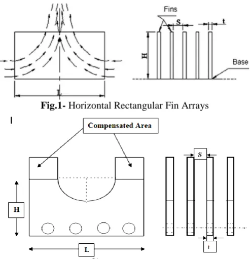
Fins were cut from rolled aluminum plates of 3mm thickness on a shearing machine. Four holes were drilled for inserting 12.7mm diameter cartridge heaters and two holes for inserting tie bolts of 6mm diameter. As per requirement of semi-circular profiled notch marking was made by using milling machine. Figure shows rectangular fin flat with and without semi-circular profiled notch. Two holes near corners on two fin flats were made with tapping for attaching thermocouple wires with the help of screws to fin flats.
Fig.1- Horizontal Rectangular Fin Arrays
Fig.2- Horizontal Rectangular Fin Arrays with a Semi Circular
Profiled Notch at the Center with area compensated type.
Spacers:
Spacers of required size were cut out aluminum sheets of thickness 2 mm and 3mm on shearing machine.
[image:2.595.307.533.142.233.2]Holes were drilled for heaters and tie bolts similar to fin flats. Figure shows sketch of a specimen spacer plates.
Fig.3- Spacer
Tie bolts, Nuts, Washers and Screws:
Tie bolts of 6mm diameter and of length 100 mm are directly purchased from market with nuts and washers. They are used for assembling fin arrays, as shown in Fig.4
Fig.4- Tie bolts, Nuts, Washers and Screws
Cartridge Heaters:
Cylindrical cartridge heaters of 12.7mm diameter and 90mm in length were used for heating purpose. Heaters have nichrome flat wire as a heating element, with mica as electriscal insulation and brass as cladding material Fig. 5 shows details of cartridge heaters. Four numbers of such heaters were used at a time.
Fig.5- Cartridge Heater
Insulating Bricks:
To avoid the thermal losses, the assembly of fin array is placed in insulating bricks cavity. These insulating bricks are made from ceramic material alumna. Reason behind using these bricks is that alumna bricks are soft and it can cut to required shape easily.
Enclosure: Array was placed in sufficiently large enclosure to provide natural convection condition.
Instrumentation:
[image:2.595.38.285.426.682.2] [image:2.595.326.539.480.592.2]© 2016, IRJET ISO 9001:2008 Certified Journal Page 2872
Heaters were connected to AC mains via dimmer stat so that input power can be varied.
Temperature measurement:
Thermocouples were used for average temperature of the fin array. Two for measuring heat lost by conduction through base of the array through insulating bricks, Two at sides of array 1.5cm apart, for measuring heat lost by conduction through sides of insulating bricks. Calibrated copper constantan thermocouples were used.
Fig.6-Schematic Diagram of experimental setup
4. Experimental procedure
i. Fin array was assembled and placed in the position, with thermocouples and heaters connected as per requirement.
ii. The predetermined heater input was adjusted with the help of dimmer stat. iii. The temperatures of assembled fin array at
different positions and ambient temperature were recorded at the time intervals of 30 min. up to steady condition. Generally it took 3 to 4 hours to attain steady state conditions.
iv. The heater input was kept constant by adjusting the dimmer stat for voltage fluctuations if any.
5.
RESULTS AND DISCUSSIONIn this section, the results are presented followed by relevant discussion. The results are obtained from the observations taken during experimentation and followed by detailed calculation procedure. The detailed observation tables were not given to avoid unnecessary increase of the thesis volume. Relevant part of observations was used to obtain the results as given in sample calculations. The notched configurations yield 50–55% higher values of heat transfer and coefficient of heat transfer compared with
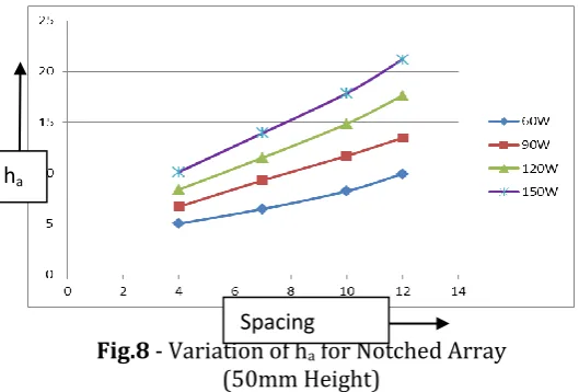
the unnotched fin for natural convection. It is also observed that the values of ha are higher at higher heater input as expected.
5.1 Effect of fin spacing on ha
Fig. 7 shows the effect of fin spacing on ha with heater
input as the parameter for unnotched array. From the figure it is clear that as the fin spacing increases the ha
increases.
Fig. 7- Variation of ha for Unnotched Array
(50mm Height)
The trend of increase in average heat transfer coefficient and hence in the Nusselt number with fin spacing is observed in case of the notched array also. Fig. 8 shows the relative performance of fin array with average heat transfer coefficient of notched array is 30 to 40% higher than corresponding unnotched array.
Fig.8 - Variation of ha for Notched Array
(50mm Height)
5.2 Effect of fin spacing on Nua
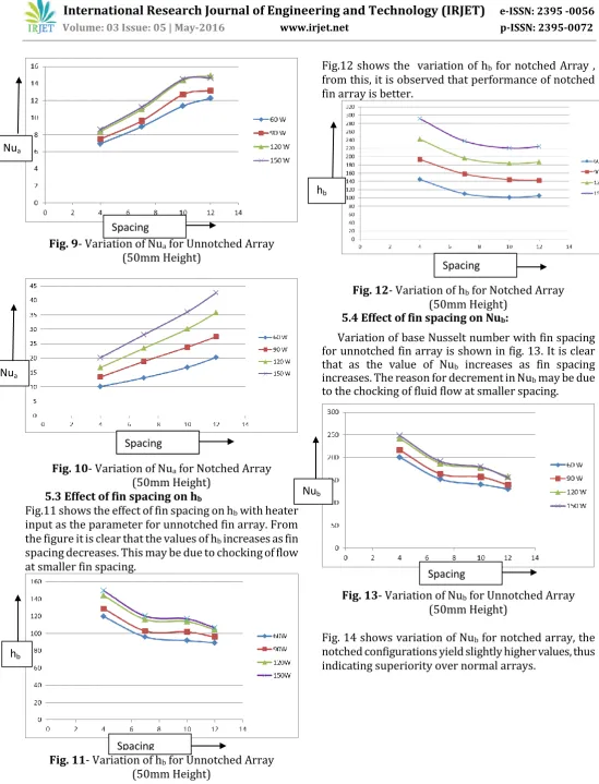
It is clear from the Fig. 9 that as spacing increases the average Nusselt number Nua increases for the notched
array. In general it is observed that the Nua increases with increase in fin spacing, this is due to reason that with increase in spacing, the fluid can flow more freely through the fin channel.
ha
ha
Spacing
[image:3.595.282.561.213.379.2] [image:3.595.39.288.232.381.2] [image:3.595.296.561.471.650.2]© 2016, IRJET ISO 9001:2008 Certified Journal Page 2873 Fig. 9- Variation of Nua for Unnotched Array
(50mm Height)
Fig. 10- Variation of Nua for Notched Array
(50mm Height)
5.3 Effect of fin spacing on hb
Fig.11 shows the effect of fin spacing on hb with heater
input as the parameter for unnotched fin array. From the figure it is clear that the values of hb increases as fin
spacing decreases. This may be due to chocking of flow at smaller fin spacing.
Fig. 11- Variation of hb for Unnotched Array
[image:4.595.13.563.46.766.2](50mm Height)
Fig.12 shows the variation of hb for notched Array ,
from this, it is observed that performance of notched fin array is better.
Fig. 12- Variation of hb for Notched Array
(50mm Height)
5.4 Effect of fin spacing on Nub:
Variation of base Nusselt number with fin spacing for unnotched fin array is shown in fig. 13. It is clear that as the value of Nub increases as fin spacing
increases. The reason for decrement in Nub may be due
to the chocking of fluid flow at smaller spacing.
Fig. 13- Variation of Nub for Unnotched Array
(50mm Height)
Fig. 14 shows variation of Nub for notched array, the
notched configurations yield slightly higher values, thus indicating superiority over normal arrays.
hb
Nua
Nua
hb
Nub
Spacing
Spacing Spacing
Spacing
Spacing
© 2016, IRJET ISO 9001:2008 Certified Journal Page 2874 Fig. 14- Variation of Nub for Notched Array
(50mm Height)
6. Conclusion
In this experimental study, an attempt is made to improve the performance of horizontal rectangular fin array by removing the less effective portion of the fin flat in the form of a semicircular profiled notch. It is observed that heat transfer coefficient increase as compensate the area at specified position. As area removed from the fin is compensated at the air entry ends of the fin it provides chance to get greater amount of fresh cold air to come in contact with hot fin surfaces. As the air moves inwards along chimney profile, it gets heated and temperature difference between the fin and entering air decreases. When this area is removed and added at place where it is more useful for heat transfer, the heat transfer increases and so does the convective heat transfer coefficient. This analysis reveals that the recommended single chimney flow pattern is maintained for the notched fin arrays. The performance of notched fin arrays is 30 to 50% superior than corresponding unnotched arrays, in terms of average heat transfer coefficient. It will be interesting to investigate further the optimization of all geometrical parameters viz. aspect ratio of the fin array, percentage area removal in the form of semi circular profiled notch as well as to find the optimum notch profile for the given heat dissipation.
REFERENCES
[1] N.K. Sane, S.D. Suryawanshi, “Natural Convection Heat Transfer from Horizontal Rectangular Inverted Notched Fin Arrays”, Journal of Heat Transfer, Volume 131, Issue: 1, Pages: 082501-1 to 082501-6, August 2009.
[2] N.G. Narve, N.K. Sane, R.T. Jadhav, “Natural Convection Heat Transfer from Symmetrical Triangular Fin Arrays on Vertical Surface”, International Journal of Scientific & Engineering Research, Volume 4, Issue 5, Pages:775 to780, May-2013.
[3] P.R. Kulkarni, “Natural Convection heat transfer from horizontal rectangular fin arrays with triangular notch at the center”, “Paper presented at NCSRT-2005, Pages: 241-244, Nov-2005.
[4] Anant Joshi, D.G. Kumbhar, “Analysis of Heat Transfer from Horizontal Rectangular (Square Notched) Fin Arrays by Natural Convection”, International Journal of Engineering Innovation & Research, Volume 4, Issue 1. [5] S.D. Wankhede, S.G. Taji, V.M. Suryawanshi, “Experimental Investigation of Heat Transfer from Inverted Notch Fin Arrays (INFA) Under Natural and Forced Convections”, IOSR Journal of Mechanical and Civil Engineering (IOSR-JMCE) Pages: 14-22.
[6] S.D. Wankhede, S.G. Taji, V.M. Suryawanshi, “Experimental Investigation of Heat Transfer from Inverted Notch Fin Arrays (INFA) Under Natural and Forced Convections”, IOSR Journal of Mechanical and Civil Engineering (IOSR-JMCE) Pages: 14-22.
[7] G.P. Lohar, S.Y. Bhosale, “Experimental Investigation of Heat Transfer for Optimizing Fin Spacing in Horizontal Rectangular Fin Array Under Natural and Forced Convection and Validation Using CFD.”, International Journal For Technological Research In Engineering, Volume 2, Issue 2, Pages:120-123, October-2014. [8] A.A. Walunj, V.S. Daund, D.D. Palande, “Review of
Performance of Rectangular Fins under Natural Convection at Different Orientation of Heat Sink”, International Journal of Thermal Technologies, Vol.5, Issue 2, Pages: 232-238, June-2015.
Nub