© 2016, IRJET ISO 9001:2008 Certified Journal Page 2329
Design, Analysis and Weight Reduction of Roller of Conveyor System
through Optimization
Piyush B. Ingale
1, Hemant P. Kadam
1, Kiran M. Narkar
1, Nilesh M. Nighot
21
Department of Mechanical Engineering, D. Y. Patil College of Engineering, Akurdi, Pune-44
Savitribai Phule Pune University, Maharashtra, INDIA
2
Project Manager
Matchwell Engineering Private. Ltd. (Unit-II), Chikhali , Pune-411062, Maharashtra, INDIA.
---***---
Abstract - Conveyors are the major parts of the industries
that play an important role for transportation of materials. Heavy and Bulky load of any sizes and shape can be transferred from one location to other. Conveyors generally used for efficient transportation of material from one location to another. The existing roller of a conveyor system is made up of mild steel which is higher in weight. Because of this higher weight bending occur between two supports after some period of duration. So aim of this work is to study existing roller of conveyor system for weight reduction. In our work we are going to reduce the weight of roller by changing the material. As these material are light in weight than mild steel so expected outcome of project is reduction in weight of roller.Key Words: Optimization, Weight Reduction, Material
Handling System.
1. INTRODUCTION
Conveyors play an important role in all the industries for efficient transportation of material from one location to other. Conveyors are generally used for safely moving of materials from one level to another, which when done by human would be time consuming and expensive. Conveyors can be installed anywhere, and are much safer than using other machine to move materials. Conveyors generally move loads of all types of shapes, sizes, and weight.Because of higher self-weight of roller, after some period bending occurs between two supports.
The problem is taken for study and involving execution for alternative design while obtaining weight optimization for the Roller of the conveyor system. The FEA methodology would be applied to solve the for finding out the structural strength of the roller and getting the reduction in weight without affecting on the strength of material handling member parts in the assembly of conveyor system.
1.1
Objectives
Objectives of the Work as follows:
Study the existing roller of conveyor system. Creating Geometric model of existing Roller of
conveyor system.
Numerical study and Analysis of roller of conveyor system is carried out.
Optimization of Roller is carried out by changing material.
Comparison is done between existing and optimized design.
1.2
Problem Statement
The aim of this work is to analyze existing roller of conveyor system by using suitable material, to minimize the overall weight of the roller. There are number of rollers in between two supports. Because of higher self-weight of roller, after some period bending occurs between two supports. It affects performance of gravity roller conveyor.
2. PROPOSED METHODOLOGY
1. Study the existing roller of conveyor system. 2. Analytical calculations, Geometrical modeling and
analysis of existing roller are carried out.
3. Selection of material is carried out on the basis of CEMA.
4. Analytical calculations, Geometrical modeling and analysis of selected material roller are carried out. 5. Manufacturing of selected material roller are carried
out.
6. Weight measurement is carried out by using weighting machine.
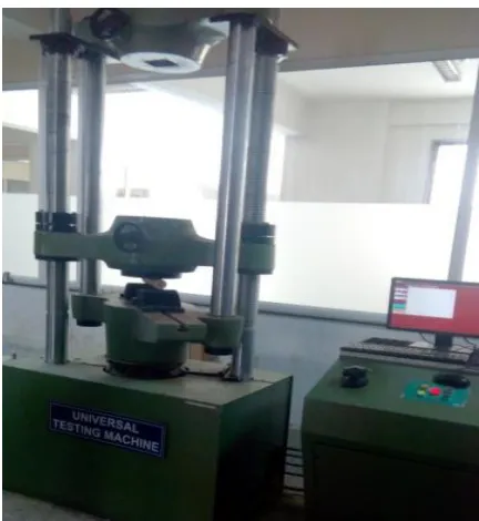
7. Experimentation is carried out for existing roller and selected material roller for calculating how much it can resist load by using UTM machine.
© 2016, IRJET ISO 9001:2008 Certified Journal Page 2330 Nomenclature
3. DESIGN FOR ROLLER
Details about Roller (By company)- D1= Outer diameter of roller = 48 mm D2 = Inner diameter of roller = 41 mm L = Width of roller = 450 mm
W= Maximum load on one roller = 40Kg N= Number of Rollers = 18
Existing Roller weight (M.S.) = 1.28Kg
3.1 Design of Existing Roller
Material – MSStandard Properties of Material E = 2.10*105 MPa, ρ= 7860 Kg/m3 Maximum Stress Calculation
W= 40kg
D1= Outer diameter of roller = 48 mm D2 = Inner diameter of roller = 41 mm w = Width of roller = 450 mm
y = Neutral axis Distance = 0.048/2 = 0.024
Considering uniformly distributed load Maximum Moment (Mmax) = W*L2 /8
Mmax = (40*9.81*.452)/8 Mmax = 9.9326 Nm
Moment of Inertia (I) = П (D14 - D24) / 64 I = П (0.0484 – 0.0414)/64
I = 1.2186*10-7 m4
Maximum bending stress σb = Mmax * y/ I
σb = 9.9326 * 0.024/ 1.2186*10-7 σb = 1.95 MPa
3.1.1 ANSYS Result of Existing Roller
Geometrical modeling of Roller is carried out in CATIA V5 R20 .Analysis is carried out in ANSYS 13.0
Load Applied-400N
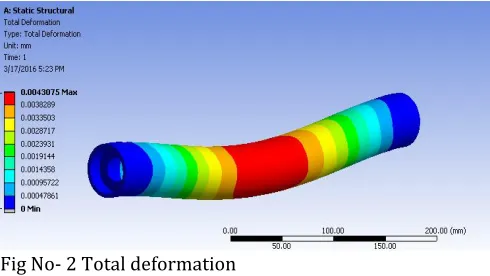
[image:2.595.32.552.32.768.2]Boundary Condition- Roller is fixed at the place where bearing is placed.
Fig No.-1 Equivalent (Von-Mises) stresses
Fig No- 2 Total deformation
3.2 Design of Polyoxymethylene (POM) or Delrin
Roller
Standard Properties of Material E = 2760 MPa, ρ=1420Kg/m3 Maximum Stress Calculation W= 40kg
D1= Outer diameter of roller = 58 mm D2 = Inner diameter of roller = 41 mm w = Width of roller = 450 mm
y = Distance from neutral axis = 0.058/2 = 0.029
Considering uniformly distributed load,
Maximum Moment (Mmax) = W*L2 /8
Mmax = (40*9.81*.4502)/8 Mmax = 9.9326 Nm
Moment of Inertia (I) = П (D14 - D24 ) / 64 I = П (0.0584 – 0.0414)/64 I = 4.16*10-7 m4
Maximum bending stress σb = Mmax * y/ I
σb= 9.9326 * 0.024/ 4.16*10-7 σb = 0.573 Mpa
3.2.1 ANSYS Results of Polyoxymethylene Roller
Geometrical modeling of Roller is carried out in CATIA V5 R20. Analysis is carried out in ANSYS 13.0
Load Applied-400N
Boundary Condition- Roller is fixed at the place where bearing is placed.
Symbol Description
σb Maximum bending stress
Mmax Maximum Moment
L Width of roller
I Moment of Inertia
W Maximum load on one roller
E Modulus of Elasticity
[image:2.595.304.549.244.382.2]© 2016, IRJET ISO 9001:2008 Certified Journal Page 2331 Fig No.-3 Equivalent (Von-Mises) stresses
Fig No- 4 Total deformation
4. EXPERIMENTATION
Experimentation is carried for existing roller and selected material roller for calculating how much it can resist load by using UTM machine.
Fig No 5- Manufacturing of Roller using Lathe Machine.
4.1 Weight Measurement
[image:3.595.304.505.287.442.2]Weight measurement is carried out by using weighting Machine
Fig No.6-Weight measurement of DELRIN Roller
Fig No.7-Weight measurement of Existing (M.S.) Roller
4.2 Testing of Roller
[image:3.595.36.267.496.642.2] [image:3.595.303.519.504.739.2]© 2016, IRJET ISO 9001:2008 Certified Journal Page 2332
[image:4.595.33.286.140.407.2]5. RESULT AND DISCUSSION
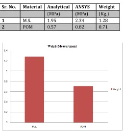
Table No. 1 - Results for Stresses
Sr. No. Material Analytical ANSYS Weight
(MPa) (MPa) (Kg.)
1 M.S. 1.95 2.34 1.28
2 POM 0.57 0.82 0.71
Chart-1 Graph for weights measurement
Chart-1: Graph for stresses
5.1 Result for Maximum load by UTM Machine
Table No. 3 – Maximum Load Measurement
Sr. No. Material Maximum load (Kg)
1 Delrin 5740
6. CONCLUSION
Existing calculations shows that factor of safety of existing roller is more than requirement and hence there is scope for certain weight reduction.
Though we get the value of deflection and stresses more than the existing, but it is in allowable limit.
Actual optimized physical model is done for validation for selected material.
Results obtained from the ANSYS and analytical calculations for existing roller are compared.
Results obtained from the ANSYS and analytical calculations for POM roller are compared.
44.57% weight reduction is achieved when compared with Delrin (POM).
Delrin Roller is then tested by using UTM Machine for calculating the maximum load.
ACKNOWLEDGMENT
I would like to express my deepest gratitude to Dr. Tapobrata Dey (PG Coordinator) & Dr. D. R. Panchagade (HOD Mechanical Dept.) and all the faculty member of the mechanical department for giving a continuous support while doing this project.
Also, I would like to thanks Mr. Tukaram N. Kachale and Mr. Vinayak Ramesh Sonawane, Mr. Ganesh Y. Thorat for their kind cooperation and support throughout the project.
REFERENCES
[1] Zhang Shirong, Xia Xiaohua “Modeling and energy efficiency optimization of belt conveyors”, Department of Automation, Wuhan University, Wuhan 430072, September, 2009
[2] S. M. Shinde, R.B. Patil “Optimization Technique Used for the Roller Conveyor System for Weight Reduction”, International Journal of Engineering Research & Technology (IJERT) Vol. 1 Issue 5, July – 2012.
[3] S.H. Masood · B. Abbas · E. Shayan · A. Kara “An investigation into design and manufacturing of mechanical conveyors Systems for food processing”, Springer-Verlag London Limited 2004.
[4] DimaNazzal, Ahmed El- Nashar “Survey Of Research
In Modelling Conveyor-Based Automated Material
Handling Systems In wafer fabs” Proceedings of
the 2007 Winter Simulation Conference.
[5] Karolewski B., Ligocki P., “Modelling Of Long Belt Conveyor” Maintenance And Reliability-2014,16 (2), PP-179-187.
[image:4.595.36.293.439.616.2]© 2016, IRJET ISO 9001:2008 Certified Journal Page 2333 [7] Zhang S, Xia X. “A new energy calcualtion model of belt
conveyor”. IEEE AFRICON 2009; Nairobi, Kenya; 23– 25 September, 2009.
[8] Marcus Haines “Development of idler roller of conveyor for Light Weight and Low Noise”.