Hard ware implementation of area and power efficient
Carry Select Adder using reconfigurable adder
structures
Neelima.V
*, R. Ramesh Babu
*** ECE, Jagruthi Institute of Engineering & Technology (JIET)
**
ECE, Jagruthi Institute of Engineering & Technology (JIET)
Abstract- In data processing processors, adder is a basic digital circuit. To perform any arithmetic operation, addition is the basic operation to perform. To compute fast arithmetic operations adder must be fastest. CSLA is the fastest adder when compare to RCA and CLA. From the structure of CSLA it is observed that there is a scope to reduce area further so that power can be lowered [3-4]. This paper proposes a new architecture of CSLA using reconfigurable adder structures (RAS) and is compared with regular SQRT CSLA, CSLA using BEC [7]. The experimental analysis shows that the proposed CSLA using RAS is having advantages regarding area and power
.
Index Terms- area efficient, low power, CSLA, BEC, SQRT CSLA and RAS
I.INTRODUCTION
In VLSI designing, most important areas of research is to design area and power efficient data processors. In digital adders, speed of addition operation depends on the propagation of carry bit through the adder. In a conventional RCA sum of each bit is generated only after the previous bit has been summed and carry propagated into the next position. Next position bits has to wait until it found the previous carry bit takes longer computation time to perform addition. For fast addition operation CLA is designed which occupies more area and consumes more power. CSLA is designed to compromise between small delay and large area of CLA and longer delay and small area of RCA [5-6]. This paper provides comparison of existed designs and proposed design of CSLA using RAS. This paper structured as follows. Section II deals with literature survey. Section III deals with CSLA using dual RCA. Section IV explains about CSLA using BEC. Section V deals with CSLA using RAS. Section VI deals with the delay and area evaluation of all groups of CSLA using RAS. Simulation results are mentioned in section VII. Results are compared and analyzed in section VIII and section IX concludes the work. Section X indicates the future scope of this work
II.LITERATURE SURVEY
By generating multiple sums by considering Cin=0 and Cin=1 and then select a carry to generate sum so that the carry propagation delay has been overcome which is proposed by o.j.Bedrij.1962 [1].
Maximum carry propagation delay in last stage of carry save adder is to be reduced through BEC method which is proposed by Ram Kumar.2010 [2]. Instead of using dual RCA in SQRT CSLA, BEC method is proposed which replaces one set of RCAs
thus the total area and power will be reduced to great extent which is proposed by B. Ram Kumar and Harish.M.kittur.2011 [7].
III.CSLA USING DUAL RCA
[image:1.612.310.542.589.733.2]Structure of 16 bit SQRT CSLA using dual RCA is shown in fig.1. It consists of five groups with different sizes of RCAs. The delay and area evaluation of basic blocks used in regular CSLA is shown in table I[7]. The numerals with in square braces of fig.1. specifies the delay.
The structure of group2 is shown in fig.2. Consists of two sets of 2 bit RCA. Selection input c1 arrival time is t=7 which is later than s2[t=6] but earlier than s3[t=8]. Therefore sum2[t=10] is the summation of delay of mux[t=3]. Similar evaluation can be done for remaining other groups[7]. Area and delay evaluation of all groups listed in table II.
TABLE I
Delay and area of basic blocks of CSLA using dual RCA
TABLE II
Delay and area count of groups in 16bit CSLA using dual RCA
Basic blocks
Delay(number of gates in critical
path)
Area (total number of
gates)
XOR 3 5
2:1 MUX 3 4 Half adder 3 6 Full adder 6 13
Group Delay (number of gates present in critical path)
Area (number of gates)
Group 1 7 26
Group 2 13 57
Group 3 16 87
Group 4 19 117
X3 X2 X1 X0 X1 X0
B3 B2 B1 B0
B0 B1 B0
5 5 4 4 3 3 2 2
[image:2.612.303.560.83.438.2]MUX 12:6 CY MUX 10:5 CY MUX 8:4 CY MUX 6:3
Fig.1. 16bit SQRT CSLA using dual RCA A3 B3 A2 B2
FA FA
C1[7]
Fig.2. Delay and Area evaluation of Group2 of CSLA using dual RCA
Fig.4. BEC logic
IV.SQRT CSLA USING BEC
Structure of 16bit SQRT CSLA using BEC logic is shown in fig.3. It also consists of 5 groups with different sizes of RCAs. Structure of BEC logic is shown in fig.4. In regular CSLA second set of RCA with Cin=1 can be replaced with BEC logic to reduce the area and power of conventional CSLA[]. Group2 of
5 5 4 4 3 3 2 2
[image:2.612.30.575.87.425.2]CY MUX 12:6 CY MUX 10:5 CY MUX 8:4 CY MUX 6:3
Fig.3. 16bit SQRT CSLA using BEC A3 B3 A2 B2
[image:2.612.57.222.464.614.2]C1[7]
Fig 5. Delay and Area evaluation of Group2 of CSLA using BEC H is a Half Adder
F is a Full Adder
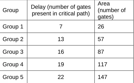
the 16 bit SQRT CSLA using BEC is shown in fig.5. Area and delay evaluation of each group is done manually by referring table1 and listed in table III.
a sum b
carry 1 2 3 delay Fig.6. Reconfigured Half Adder
2-b RCA
5-b RCA 5-b RCA
2-b RCA 2-b RCA
3-b RCA 3-b RCA
4-b RCA 4-b RCA
CY 6:3 MUX[3]
FA HA
2-b RCA
6-b BEC 5-b RCA
3-b BEC 2-b RCA
4-b BEC 3-b RCA
5-b BEC 4-b RCA
CY 6:3 MUX[3] HA FA
A[15:11] B[15:11] A[10:7] B[10:7] A[6:4] B[6:4] A[3:2] B[3:2] A[1:0] B[1:0] A[15:11] B[15:11] A[10:7] B[10:7] A[6:4] B[6:4] A[3:2] B[3:2] A[1:0] B[1:0]
Cin=’0 ’
Cin=’0’ Cin=’0’ Cin=’0’ Cin Cin=’0’ Cin=’0’ Cin=’0’ Cin=’0’ Cin
Cyout sum[15:11] sum[10:7] sum[6:4] sum[3:2] sum[1:0] Cyout sum[15:11] sum[10:7] sum[6:4] sum[3:2] sum[1:0]
Sum2[10] Sum3[11]
C3[10]
Sum2[10] Sum3[12]
5 5 4 4 CY MUX12:6 CY MUX 10:5 CY
[image:3.612.43.578.51.761.2]5 4
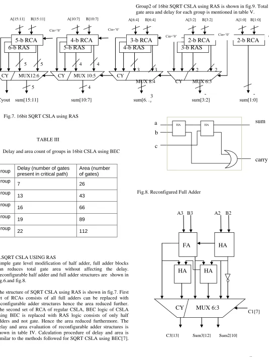
Fig.7. 16bit SQRT CSLA using RAS
TABLE III
Delay and area count of groups in 16bit CSLA using BEC
V.SQRT CSLA USING RAS
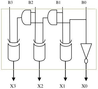
[image:3.612.350.559.465.726.2]Simple gate level modification of half adder, full adder blocks can reduces total gate area without affecting the delay. Reconfigurable half adder and full adder structures are shown in fig.6.and fig.8.
The structure of SQRT CSLA using RAS is shown in fig.7. First set of RCAs consists of all full adders can be replaced with reconfigurable adder structures hence the area reduced further. The second set of RCA of regular CSLA, BEC logic of CSLA using BEC is replaced with RAS logic consists of only half adders and not gate. Hence the area reduced furthermore. The delay and area evaluation of reconfigurable adder structures is shown in table IV. Calculation procedure of delay and area is similar to the methods followed for SQRT CSLA using BEC[7].
Group2 of 16bit SQRT CSLA using RAS is shown in fig.9. Total gate area and delay for each group is mentioned in table V.
3 3 2 2 MUX 8:4 CY MUX 6:3
2 2
Fig.8. Reconfigured Full Adder
A3 B3 A2 B2
C1[7]
Group Delay (number of gates present in critical path)
Area (number of gates) Group
1 7 26
Group
2 13 43
Group
3 16 66
Group
4 19 89
Group
5 22 112
2-b RCA
6-b RAS
5-b RCA
3-b RAS
2-b RCA
4-b RAS
3-b RCA
5-b RAS
4-b RCA
a
c
b
sum
carry
FA
HA
CY MUX 6:3
HA
HA
A[15:11] B[15:11] A[10:7] B[10:7] A[6:4] B[6:4] A[3:2] B[3:2] A[1:0] B[1:0]
Cyout sum[15:11] sum[10:7] sum[6:4] sum[3:2] sum[1:0]
Cin
Cin=’0’ Cin=’0’
Cin=’0’ Cin=’0’
3
Sum2[10] Sum3[12]
C3[13]
Fig.9.group 2 of CSLA using RAS
TABLE IV
Delay and area of reconfigurable structures of CSLA using RAS
Basic blocks
Delay(numb er of gates in critical path)
Area (total number of gates) 2:1 mux 3 4 Half adder 3 4
Full adder 6 9
VI.DELAY AND AREA EVALUATION METHODOLOGY OF 16-BIT CSLA USING RAS
Evaluation of delay and area of each group of the proposed structure is similar to the evaluation of SQRT CSLA using BEC. SQRT CSLA using RAS uses reconfigurable structures of half adder and full adder having less number of gates, hence area reduced to great extent.
Estimation of maximum delay of 16 bit CSLA using RAS is similar to the delay estimation of 16 bit CSLA using BEC[7]. By referring Tables III and V, it is clear that, the gate count in CSLA using RAS is reduced without affecting the delay.
Area evaluation has been determined as follows
Group1:-
Gate count=FA*2 =9*2=18 Group2:-
Gate count=FA+(HA*3)+NOT+(MUX*3) =9+(4*3)+1+(4*3)=34
Group3:-
Gate count=(FA*2)+(HA*4)+NOT+(MUX*4) =(9*2)+(4*4)+1+(4*4)=51
Group4:-
Gate count=(FA*3)+(HA*5)+NOT+(MUX*5) =(9*3)+(4*5)+1+(4*5)=68
Group5:-
Gate count=(FA*4)+(HA*6)+NOT+(MUX*6) =(9*4)+(4*6)+1+(4*6)=85
(ref table IV for individual gate areas of RAS blocks)
TABLE V
Delay and area count of groups in 16bit CSLA using RAS
VII. SIMULATION RESULTS input1 input2
Group
Delay (number of gates present in critical path)
Area (number of gates)
Group 1 7 18
Group 2 13 34
Group 3 16 51
Group 4 19 68
Group 5 22 85
Sumout with Cin=’1’ Sumout
TABLE VI
Comparison of CSLA using RAS with CSLA using BEC and CSLA using dual RCA
VIII.RESULT ANALYSIS
Efficiency of the SQRT CSLA can be evaluated using the comparison of number of gates utilized in the existing adders and the proposed SQRT CSLA using RAS which is shown in table VI. From the comparison table it is clear that, the proposed SQRT CSLA using RAS saves 178 gate areas than regular CSLA, 80 gate areas than SQRT CSLA using BEC without affecting gate delays. So the proposed design has given better results as compared to existing designs.
IX.CONCLUSION
A simple gate level reconfigurable approach of full adder and half adder is proposed in this paper to reduce the area and power
of SQRT CSLA. The proposed CSLA with RAS is simple, low power, area efficient for VLSI implementation.
X.FUTURE SCOPE
This proposed design is implemented for 16bit word size and parameters like area, delay, power are evaluated. This work can be further extended for 32 bit, 64 bit, 128 bit and so on.
REFERENCES
[1] O.J.BEDRIJ,“CARRY-SELECT ADDER,”IRETRANS.ELECTRON.COMPUT.
PP.340–344,1962.
[2]B.RAMKUMAR,H.M.KITTUR, AND P.M.KANNAN,“ASIC IMPLEMENTATION
OF MODIFIED FASTER CARRY SAVE ADDER,”EUR.J.SCI.RES., VOL.42, NO.1, PP.
53–58,2010.
[3]T.Y.CEIANG AND M.J.HSIAO,“CARRY-SELECT ADDER USING SINGLE RIPPLE
CARRY ADDER,”ELECTRON.LETT., VOL.34, NO.22, PP.2101–2103,OCT.1998.
[4]Y.KIM AND L.-S.KIM,“64-BIT CARRY-SELECT ADDER WITH REDUCED AREA,”
ELECTRON.LETT., VOL.37, NO.10, PP.614–615,MAY 2001.
[5] J.M.RABAEY,DIGTAL INTEGRATED CIRCUITS—ADESIGN PERSPECTIVE.
UPPER SADDLE RIVER,NJ:PRENTICE-HALL,2001.
[6]Y.HE,C.H.CHANG, AND J.GU,“AN AREA EFFICIENT 64-BIT SQUARE ROOT
CARRY-SELECT ADDER FOR LOW POWER APPLICATIONS,” IN PROC. IEEEINT.
SYMP.CIRCUITS SYST.,2005, VOL.4, PP.4082–4085.
[7] Ram kumar, B. and Harish M Kittur, (2011) ‗Low Power and Area Efficient Carry Select Adder‘, IEEE Transactions on Very Large Scale Integration (VLSI) Systems, pp.1-5.
AUTHORS
First Author – Neelima.v, Mtech(VLSI), Jagruthi Institute of
Engineering & Technology(JIET) , [email protected].
Second Author – R.Ramesh Babu, assistant professor, Jagruthi
Institute of Engineering & Technology(JIET), [email protected].
Group
16 bit SQRT CSLA using dual RCA
16 bit SQRT CSLA using
BEC
16 bit SQRT CSLA using