ANALYSIS OF VRPPIC AND PPIC FOR SISO AND SIMO
MC-CDMA UPLINK SYSTEM
1
NOOR MOHAMMED. V, 2P. S. MALLICK, 3L. NITHYANANDAN
1
Member IEEE,
2 Senior Member IEEE
3 Pondicherry Engineering College, India.
Email: [email protected], [email protected] , [email protected]
ABSTRACT
This paper presents an extended version of Partial Parallel Interference Cancellation (PPIC) called Variance reduced Partial Parallel Interference Cancellation (VRPPIC) for multicarrier code division multiple access uplink systems. The combination of PPIC receiver and new bit estimator is called VRPPIC detector. This realization is derived for the main PPIC operation and soft decision (SD) from PPIC, which are linear combination of the bit estimator using appropriate Weighting Factors (WF). These weighting factors are derived from Partial Parallel Interference Cancellation (PPIC) weighting factors. It is used to reduce the conditional variance of the final stage signal estimation. An Optimal Weighting Factor (OWF) selection algorithm has been derived for VRPPIC detector scheme, to minimize a monotonically increasing condition variance function. For all the interference cancellation stages the derived OWFs are equal and can easily be obtained from a linear function of active users. Simulation has been done in VRPPIC detector and PPIC detector using optimal weighting factors and randomly selected weighting factors. The result shows that the
VRPPIC with OWFs outperforms both VRPPIC and PPIC with randomly selected weighting factors. Also it
is shown in this paper that if there are multiple antennas at the receiving end, the performance of the detector is further improved. This leads to generalization that if data comes from single stream (single input) and there are multiple outputs (antennas) at the receiving end, the detector for multiple reception MC-CDMA strikingly outperforms the conventional systems with single antenna at the receiving end.
Keywords:Optimal Weighting Factor (OWF), Multiuser Detection, Variance Reduced Partial Parallel
Interference Cancellation (VRPPIC), Multiple Access Interference (MAI).
1. INTRODUCTION
Multicarrier Code Division Multiple Access (MC-CDMA) is a combination of Code Division Multiple Access (CDMA) and Orthogonal Frequency Division Multiplexing (OFDM). The main advantages of the MC-CDMA systems are efficient utilization of spectrum and immunity to multipath impairments. This MC-CDMA is one of the promising techniques for fourth generation wireless communication systems. The main drawback of this system is Multiple Access Interference (MAI). To mitigate this drawback, Multiuser Detection scheme is used for an MC-CDMA uplink system.
There are many multiuser detection schemes have been proposed in the literature [3],[4]. Amidst them the attention has been focused on multistage parallel interference cancellation (PIC), because of its low latency and low complexity. But it fails to
ISSN: 1992-8645 www.jatit.org E-ISSN: 1817-3195
(BER) were suggested for CDMA system in [10] and [11]. However if the number of IC stages increases then complexity of BER also increases, so these methods are commonly not suitable for applications with more than two IC stages.
In this paper we have considered the PPIC and an extended version of PPIC (i.e) Variance Reduced PPIC(VRPPIC), for uplink MC-CDMA system. Further we have shown that this can also be used in Single Input and Multiple Output (SIMO) systems.
2. SYSTEM MODEL
Consider synchronous MC-CDMA uplink system, having K number of users and N numbers of subcarriers, which is equal to spreading factor G for each user. The MC-CDMA uplink modulators performs the Inverse Discrete Fourier Transform (IDFT) to generate the time domain transmitter signal for user k, it is given as
𝒛𝒏
𝒌 = 𝟏/𝑵∑
𝑵−𝟏𝒊=𝟎 𝒁Rik
e
j(2π/N)ni=
1/𝑁 ∑𝑁−1(𝑖=0 𝑎k
c
iks
k)ej
(2π/N)ni(1)
where signal amplitude represents as 𝑎k , the ith chip of the normalized spreading code vector ck is represented as 𝑐𝑖𝑘 and signal data for the user k represents as 𝑠𝑘. After insertion of the cyclic prefix the signal is transmitted through a channel. The impulse response vector of the channel for user k is given by
hk =[α0kα1k …….,α0k αL-1k]T (2)
the channel fading gain of the lth path is represented as αlk
.
Now at the base station, the received data ( i.e nth time sample without cyclic prefix) is the summation of the distorted transmitted signal from each user and the Additive White Gaussian Noise (AWGN) gn with variance N0/2 respectively, in the in-phase branch and the quadrature branch[12] is given by
xn = ∑𝐾𝑘=1𝑧Rn
k
⊗ αnk + gn , n =0,1,….,N-1
(3)
Here ⊗ denotes circular convolution [1]. The
above equation can be represented in vector form as 𝑋 = ⎣ ⎢ ⎢ ⎢ ⎢ ⎡ 𝑥𝑥01
. . . 𝑥𝑁−1⎦
⎥ ⎥ ⎥ ⎥ ⎤ =∑ ⎝ ⎜ ⎛ ⎣ ⎢ ⎢ ⎢ ⎡ 𝑧0𝑘
𝑧1𝑘
. . 𝑧𝑁−1𝑘
𝑧𝑁−1𝑘
𝑧0𝑘
. . 𝑧𝑁−2𝑘
. . . . . . . . . .
𝑧𝑁−𝐿+1𝑘
𝑧𝑁−𝐿+2𝑘
. . 𝑧𝑁−𝐿𝑘 ⎦
⎥ ⎥ ⎥ ⎤ 𝑋 ⎣ ⎢ ⎢ ⎢ ⎡ 𝛼0𝑘
𝛼1𝑘
. . 𝛼𝐿−1𝑘 ⎦
⎥ ⎥ ⎥ ⎤ ⎠ ⎟ ⎞ + 𝑔 𝐾 𝑘=1
(4) Here, g= [g0 , g1 ,…., gN-1]
T
(5)
The MC-CDMA uplink demodulator performs Discrete Fourier Transform (DFT) on the time domain signal in the (4), the received data vector (i.e frequency domain) is represented in (6), where F is an N point DFT matrix containing the twiddle factor FN =(-j2𝜋/𝑁), A is the diagonal amplitude
matrix, s consists of all users data, w is the DFT of g, and H is channel matrix consists of spreading code chip cik and the frequency response Hik of the
ith subcarrier for user K.
From (6) it is observed that the user data’s overlapping in the frequency domain with the code non-orthogonality will cause MAI in the received data vector.
XF=FX =HAs+w, XF: N x 1 (6)
So, now to collect the energy of the received data vector scattered over the frequency domain, a linear de-spreader D on XF is performed, [1]
y= DH xF
= DHHAs + DHw
= [diag(DHH)+ DHH - diag(DHH)] As + DHw = diag(DHH) As + [DHH - diag(DHH)] As +DHw = Bs + i + wC , Y : N X 1 (7)
where, the Hermitian transpose is represented as
(•)H , Bs = diag(DHH)As is containing the data
vector s, i = [DHH - diag(DHH)]As is the MAI vector, and wC = DHw is the AWGN vector.
From the de-spreader output vector y, the data
vector s is estimated using hard decisions
estimation on y. This is equivalent to parallel single user detection method, which frequently does not provide satisfactory performance. The PPIC detector can be performed based on the de spreader output y in order to have a more correct estimate of the data vector s. The MAI vector i in the above equation is estimated and partially removed from y
IC stage. The optimum choice of WF can enhance the PPIC performance. Since PPIC performance highly depends on WFs.
The MAI estimates can be represented in vector form using (7) (i.e) mth IC stage
i(m)=[ DHHe - diag(DHHe)]APh(m-1) , i(m): K X 1 (8)
Here, estimate of H is represented as He and Ph(m-1)
is the hard decisions of the signal estimations at the prior stage generated from the soft decisions Ps(m-1)
equation (8) also exposes that the channel state information and transmission power condition of each user are essential for the MAI reconstruction. With the MAI estimate in (8), the PPIC detector [1] operation can be written as follows
Ps(m)=q(m)(y-i(m))+(1-q(m))Ps(m-1)
ŝ(m) = Ps(m))= sign[Ps(m)]
Initial condition: Ps(0)= y and Ph(0)=sign[y]
Ps(m),Ph(m):K×1 (9)
where, the WF is represented as q(m), which
determine the amount of interference cancellation at the mth IC stage and hard decision estimation is represented as sign [•].
3. THE VRPPIC DETECTOR
3.1 New Bit Estimator
The PPIC performance highly depends on the WFs, a new bit estimator combines the soft estimates from the PPIC operation to form VRPPIC detector [1]. Rewriting (9) as
Ps(m)= (y-i(m))q(m) +(1-q(m)) Ps(m-1)
=(y-i(m))+(1-q(m))[Ps(m-1)-(y-i(m))] (10)
and substituting (7) into (10), we obtain
Ps(m)= (y-i(m)) +(1-q(m))[Ps(m-1)- (y-i(m))]
=Bs + wC +{ i-[q(m) i(m)+(1-q(m))[q(m-1) i(m-1)
+(1-q(m))(1-q(m-1))q(m-2) i(m-2+ ……….+ (1-q(m))( 1-q(m-1))…(1-q(2))q(1) i(1)]}
= Bs + wC + ir(m) each IC stages.
4. SINGLE RECEPTION SYSTEM
In this system a single antenna at the receiving end has been taken. All the data which is coming from the transmitting end is passed on to both the detectors separately, for performance analysis.
4.1 The Ppic Detector Operation
At the mth IC stage as in [7], the MAI estimate using equation (7) is
Ps (m)
= (y-i(m)) +(1-q(m))[Ps (m-1)
- (y-i(m))] = Bs + wC +{ i-[q
(m)
i(m)+(1-q(m))[q(m-1) i(m-1) +(1-q(m))(1-q(m-1))q(m-2) i(m-2+ …+(1-q(m))( 1-q
(m-1))…(1-q(2))q(1) i(1)]}
= Bs + wC + ir(m) (11)
where ir(m) is the "residual MAI vector"
representing the rest of MAI after the interference
cancellation performed at the mth stage. Each
element of the residual MAI vector can be observed as a Gaussian random variable when K is large enough [5]. Substituting the MAI vector in (7) and the MAI estimate vector in (8) into the residual MAI vector in (11), then
ir(m) = [DHH - diag(DHH)]As
-{[DHHe - diag(DHHe)]A
X [γm(m) Ph(m-1) + γm(m-1) Ph(m-2) +….+ γm(1) Ph(0)
(12) where, γm(n) =(1-q(m)) (1-q(m-1))… (1-q(n+1))q(n) for
1≤ n ≤ m and γm(m) =q(m). From (12) data vector s
can be estimated using weighted sum of hard decision estimation which implies that the PPIC detector inherently uses an average bit estimator. The bit estimator for the mth IC stage is given by Ŝ(m)= [γ
m (m)
Ph (m-1)+ γ
m (m-1)
Ph
(m-2)+….+ γ m
(1)
Ph (0)
]
(13) An additional bit estimator that combines soft decision estimation generated from each IC stage of PPIC, which improve the performance of PPIC, this extended PPIC structure would reduce the conditional variance of the final signal estimate so we call it VRPPIC. Following (13), the additional bit estimator[1] can be express as
Ś = [γm(m) P
h(m-1)+ γm(m-1) Ph(m-2)+….+ γm(1) Ph(0)]
Ŝ=sign[Ś] (14) where, γM+1
(m )
= (1-q(M+1)) (1-q(M))…
(1-q(m+1))q(m) for1≤ m ≤ M and γM+1(M+1) =q(M+1).PS
(m-1) is the soft decision from the (m+1)th IC stage, Ś
is the final soft decision estimate of the data vector
s, and Ŝ is the hard decision corresponding to Ś.
The q(M+1) does not actually exist, to determine
γM+1(m) for 1 ≤ m ≤ M+1, we can simply let q(M+1)
=q(M ).
4.2 An OWF Selection Algorithm for VRPPIC
Subject to a given first-IC-Stage’s WF
To derive the OWFs, the following assumption is made
(i) H is the channel matrix, which is the
ISSN: 1992-8645 www.jatit.org E-ISSN: 1817-3195
-5 0 5 10 15 20 25
10-3 10-2 10-1 100 Eb/No, dB BER
bPR 0.75 0.85 0.95 bVR 0.75 0.85 0.95 bPR 0.65 0.45 0.25 bVR 0.65 0.45 0.25 bPo 0.65 bVo 0.65
(ii) A is the diagonal amplitude matrix (
identity matrix) that is each user have perfect power control (PC)
(iii) s, wc, and each iP
(m)
P
are mutually independent.
(iv) 0 <qP (1 )
P
≤qP (2 )
P≤ . . . ≤qP (M )
P
< 1 [7].
With assumptions (i) to (iv) we derive the conditional variance from VRPPIC, which is estimated as follows
σRv RP 2
P
= var{ Ś|S } ~ var{[qP
(M )
P
+ (1-qP (M-1 )
P
)qP (M )
P
+… +(1-qP (M )
P
) (1-qP (M )
P
) + … (1-qP
(2)
P
)qP (1)
P
]wRcR} + var{qP (M ) P qP (M ) P iP (m) P } + var{qP (M ) P (1-qP (M) P )qP (M-1 ) PP + P (1-qP (M) P )qP (M ) P (qP (M-1 ) P
)] iP
(m-1)
P
} (15) From (15) it can be realized that conditional variance for a fixed signal to noise ratio (SNR) is a function of all the WFs. In general, if the detector is unbiased, a small conditional variance of final signal estimate from a detector implies good performance. As exposed in [6], in PPIC first IC stage WF should be properly selected to balance the bias effect and interference cancellation performance. Referring to [10] both real and imaginary part of MAI is approximated as Gaussian. The OWF selection algorithm for the VRPPIC detector subject to a given first IC-stage’s WF can be defined by
min σRvRP 2 qP (2), P qP (3) P ……qP (M) P
subject to qP (1)
P
=qRG RP (1)
Pand(iv.) (16)
where, qRG RP (1)
P
is the OWF of single-stage PPIC that needs to be determined before solving equation (12). By differentiating equation (15) with respect to qP
(M )
P
(the last-IC-stage’s WF), it can be proved that the conditional variance σRvRP
2
P
increases
monotonically with qP
(M )
P
. With qRG RP (1)
P
and this monotonically increasing property, the solution to (16) can easily be derived as follows:
qP (M) P =qP (M-1) P
= . . . =qP (2)
P
=qP (1)
P
=qRG RP (1)
P
(17)
Results of (17) offers a simple OWF selection rule for VRPPIC, where the complexity is clearly much lower than that of the OWF selection patterns [11].
5. MULTIPLE RECEPTION SYSTEM
Here it is considered that there are multiple antennas at the receiving end. With this consideration all the further analysis of the detector has been kept same as in section III. Because the work is totally restricted to the
receiver side, with simple assumption that the data comes from a single antenna i.e.an antenna at the transmitting end, the system can work well for the SIMO MC-CDMA Uplink systems.
6. SIMULATION RESULTS
In our simulation work, we consider Rayleigh fading channel with four paths for each user, and modulation techniques used is QPSK. An assumption is made that the channel has a constant impulse response and there is no Doppler shift during the burst transmission [12]. The channel is normalized by ∑ (𝐿−1𝑙=0 σRk,lRP
2
P
) =1 where σRk,lRP 2
P
is the variance of the lP
th
P
path. The spreading factor G=16 (spreading code is pseudo noise sequence) and dispreading scheme is the maximal ratio combining techniques.
The simulation results from Fig. 1 to Fig. 4 correspond to the single reception system [1] and Fig.5 is the multiple reception system. To explain the simulation results shown in Fig.1 and Fig.2, the following representations are adopted: bPR is the randomly selected weighting factor for PPIC, bVR is the randomly selected weighting factor for VRPPIC
Fig.1 Error Performance Of PPIC And
-5 0 5 10 15 20 25 10-3
10-2 10-1 100
Eb/No, dB
BER
PC error=30% & CE error=30% PC error=20% & CE error=20% PC error=10% & CE error=10% Perfect PC & Perfect CE
-5 0 5 10 15 20 25
10-3 10-2 10-1 100
Eb/No
BER
[image:5.612.65.534.70.368.2]PC error=20% & perfect CE CE error =20% & Perfect PC
[image:5.612.60.536.77.687.2]Fig.2 Impact Of Interference Cancellation Stages On Error Performance
Fig 3 Impact Of Imperfect Channel Condition On Error
Performance
[image:5.612.56.279.387.676.2]Fig.4 Impact Of Perfect And Imperfect Channel Condition On Error Performance
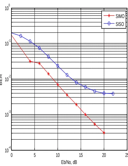
Fig.5 Impact Of SISO And SIMO Error Performance
0 5 10 15 20 25
10-4 10-3 10-2 10-1 100
Eb/No, dB
BER
SIMO SISO
1 2 3 4 5 6 7
10-3 10-2 10-1
Number of IC stages(M)
BER
[image:5.612.326.539.399.675.2]ISSN: 1992-8645 www.jatit.org E-ISSN: 1817-3195
bPo is optimum weighting factor for PPIC and bVo is optimum weighting factor for VRPPIC. Fig. 1 shows the comparison of the performance of VRPPIC and PPIC using different WF selection schemes under perfect PC and CE in a 10-user scenario. Here the number of stages we have taken is 3.It can be seen from Fig.1 that as the Eb/No is increasing, the performance of VRPPIC using the OWFs gets better and better with reduction in BER as compared to VRPPIC( or PPIC) using RS-WFs. Fig. 2 also gives us the similar type of conclusion and it can be seen that the as the number of interfering cancellation(IC) stages is increasing, the performance of VRPPIC using the OWFs keeps improving as compared to VRPPIC ( or PPIC) using RS-WFs. From the analysis of Fig. 3 and 4 it can be seen VRPPIC detector with the OWF shows a comparative performance to about 20% error in both PC and CE as in Fig. 3. It should be noted that in Fig.4 both perfect and imperfect scenarios are taken into consideration where as Fig.3 we use only imperfect scenarios. In Fig. 5 it can be seen that with multiple reception MC-CDMA Uplink system the performance of the detector significantly outperforms the MC-CDMA Uplink system with single reception.
7. CONCLUSION
The performance of the two detectors VRPPIC and PPIC has been compared on the various set of parameters and it is concluded that the VRPPIC using the Optimum Weighting Factor (OWFs) significantly outperforms the PPIC as well as VRPPIC using the Randomly Selected Weighting Factor (RS-WFs).The choice of the weighting factor plays a key role as the number of interfering cancellation stages increases and theoretically it was shown that the optimum weighting factor for each stage should be equal rather than different for the improved performance. Moreover the optimum choice of the weighting factor is countering the effect to some percentage of error in power control and channel estimation as this is proved from the simulation work. Further it is shown as the number of interfering cancellation stages are increasing the performance of VRPPIC gets better and with this a conclusion can be drawn that for a better estimate of the user signal the number of interfering stages should be a large value.
Moreover, it is shown that if there are multiple antennas at the receiving side the performance of the two detectors VRPPIC and PPIC gets improved outstandingly as compared to the one with single antenna at the receiving side. Since our work is
totally restricted to the receiving side, an assumption that the data comes from single stream (single input) and multiple reception is taken, so together it forms a SIMO system and with this a realization can be made that multiple reception can further help in interference cancellation by combating the effect of multipath fading which leads to further improvement in the performance of the detector.
REFERENCES
[1] Chin-Liang Wang, Chang-Chen Chu and Chih-Chiang Wu, “Variance-Reduced Partial Parallel Interference Cancellation for MC-CDMA Uplink Systems”, IEEE Trans. Wireless Commun., Vol. 8, No.10, October 2009, pp. 4951-4956.
[2] R. van Nee and R. Prasad, OFDM for Wireless Communications Systems Boston/London: Artech House, 2000.
[3] S. Verdú, Multiuser Detection. Cambridge, U.K.: Cambridge Univ.Press, 1998.
[4] P. H. Tan and L. K. Rasmussen, “Linear interference cancellation in CDMA based on iterative techniques for linear equation systems," IEEE Trans. Commun., vol. 48, No.12, Dec. 2000, pp. 2099–2108.
[5] M. K. Varanasi and B. Aazhang, “Multistage detection in asynchronous code-division multiple-access communications," IEEE Trans. Commun. vol. 38, No.4, Apr. 1990, pp. 509–519.
[6] R. M. Buehrer and S. P. Nicoloso, “Comments on partial parallel interference cancellation for
CDMA," IEEE Trans. Commun., vol. 47,
No.5, May 1999, pp. 658–661.
[7] D. Divsalar, M. K. Simon, and D. Raphaeli, “Improved parallel interference cancellation for CDMA," IEEE Trans. Commun., vol. 46, No.2, Feb. 1998, pp. 258–268.
[8] S. Moshavi, “Multi-user detection for
DS-CDMA communications," IEEE Commun.
Mag., vol. 34, No.10, Oct. 1996, pp. 124–136. [9] M. Chen, Y. Li, S. Cheng, and H. Wang, “On
the bit estimator of partial parallel interference cancellation for DS-CDMA," in Proc. IEEE Int. Conf. Commun., Helsinki, Finland, June 2001, pp. 1945–1949.
[11] C.-H. Hu, S.-Q. Li, Y.-X. Tang, and Z.-L. Li, “Performance and optimization of multistage partial parallel interference cancellation for wideband CDMA systems in multipath fading channels," IEEE Trans. Veh. Technol., vol. 55, No.4, July 2006, pp. 1137–1158.
[12] J. Proakis, Digital Communications, 4th ed.
![Assessment of Physiological Health Status in Relations to Different Anthropometric and Cardio respiratory Measures of Head Supported Load Carrying Male Porters of Sikkim, India [Article Retracted]](data:image/gif;base64,R0lGODlhAQABAIAAAP///wAAACH5BAEAAAAALAAAAAABAAEAAAICRAEAOw==)