EK-OFM 16-UG-001
DFM Series
Intelligent
Communications
Processor
User Guide
© Digital Equipment Corporation 1986 AU Rights Reserved
1 st Edition, January 1986
The information in this document is subject to change without notice and should not be construed as a commitment by Digital Equipment Corporation. Digital Equipment Corporation assumes no responsibility for any errors that may appear in this document
Printed in U. S.A.
The following are trademarks of Digital Equipment Corporation:
~DmDDmD
DEC DECmate DECset
DECsystem-lO DECSYSTEM-20 DECUS
DECwriter DIBOL MASSBUS PDP P/OS Professional Rainbow RSTS
RSX Scholar ULTRIX UNIBUS VAX VMS
VT
PREFACE
CHAPTER 1
1.1 1.2 1.2.1 1.2.2 1.2.3 1.2.4 1.2.5 1.2.6 1.3 1.3.1 1.3.2 1.3.3 1.3.4 1.3.5
CHAPTER 2
2.1 2.2 2.3 2.3.1 2.3.1.1 2.3.1.2 2.3.1.3 2.3.1.4 2.3.2 2.3.3 2.4 2.4.1 2.4.2 2.5 2.5.1 2.5.2 2.6 2.6.1 2.6.2 2.7 2.8 2.9 2.9.1 2.9.2 2.10 CONTENTS Page INTRODUCTION
MULTIPLEXING ••••••••••••••••••••••••••••••••••••••• 1-1 DFM FEATURES ••••••••••••••••••••••••••••••••••••••• 1-4 Channel Switching and Port Contention •••••••••••• 1-4 Network Management and Contro1 ••••••••••••••••••• 1-5 Intelligent Interfacing •••••••••••••••••••••••••• 1-7 Comprehensive Diagnostics •••••••••••••••••••••••• 1-8 Expansion Capabi1ity ••••••••••••••••••••••••••••• 1-8 Maximized Throughput ••••••••••••••••••••••••••••• 1-9 APPLICATIONS AND CONFIGURATIONS ••••••••••••••••••• 1-11 Switching and Contention •••••••••••••••••••••••• 1-11 Tail Circuits ••••••••••••••••••••••••••••••••••• 1-14 Satellite Links ••••••••••••••••••••••••••••••••• 1-17 Synchronous Channels •••••••••••••••••••••••••••• 1-18 Multiple DFM Configuration •••••••••••••••••••••• 1-18
PREINSTALLATION PLANNING
G ENE RA L. • • • • • • • • • • • • • • • • • • • • • • • • • • • • • • • • • • • • • • • • • • • 2-1
CHAPTER 3 3.1 3.2 3.3 3.3.1 3.3.2 3.3.3 3.3.4 3.4 3.4.1 3.4.2 3.4.3 3.5 3.5.1 3.5.2 3.5.3 3.5.4 3.6 3.6.1 3.6.2 3.6.2.1 3.6.2.2
CHAPTER 4
4.1 4.2 4.3 4.3.1 4.3.2
CHAPTER 5
5.1 5.2 5.3 5.4 5.4.1 5.4.2 5.5
CONTENTS (Cont)
Page
INSTALLATION
G ENE RA L. • • • • • • • • • • • • • • • • • • • • • • • • • • • • • • • • • • • • • • • • • • • 3-1
UNPACKING AND INSPECTION ••••••••••••••••••••••••••• 3-l VISUAL INSPECTION •••••••••••••••••••••••••••••••••• 3-l Removing the Bezel ••••••••••••••••••••••••••••••• 3-l Checking the Identification Decal •••••••••••••••• 3-l Checking the Modules ••••••••••••••••••••••••••••• 3-3 Rear Panel Connectors •••••••••••••••••••••••••••• 3-4 CONTROLS AND INDICATORS •••••••••••••••••••••••••••• 3-6 Control Module ••••••••••••••••••••••••••••••••••• 3-6 Channel Expansion Module ••••••••••••••••••••••••• 3-6 Integral Modem Module •••••••••••••••••••••••••••• 3-6 PREINSTALLATION BENCHTEST AND OPERATOR
FAMILIARIZATION ••••••••••••••••••••••••••••••••••• 3-l8 Logging on with USER and SYSTEM MANAGER Level
Passwords ••••••••••••••••••••••••••••••••••••••• 3-l8 Setting System Parameters ••••••••••••••••••••••• 3-20 Entering Data Channel Command Mode •••••••••••••• 3-24 Switched Channel Operation •••••••••••••••••••••• 3-25 INSTALLATION •••••••••••••••••••••••••••••••••••••• 3-28 DFM Cabling ••••••••••••••••••••••••••••••••••••• 3-29 Installing Module Options ••••••••••••••••••••••• 3-29 Installing Integral Modems •••••••••••••••••••• 3-30 Installing Channel Expansion Modules •••••••••• 3-3l
USING THE DFM UNIT
INTRODUCTION ••••••••••••••••••••••••••••••••••••••• 4-l UNSWITCHED CHANNELS •••••••••••••••••••••••••••••••• 4-l SWITCHED CHANNELS •••••••••••••••••••••••••••••••••• 4-2 Remote Switching Application ••••••••••••••••••••• 4-2 Local Switching Application •••••••••••••••••••••• 4-8
COMMAND DESCRIPTIONS
CHAPTER 6 6.1 6.2 6.2.1 6.2.2 6.2.3 6.2.4 6.2.5 6.2.6 6.2.7 6.3 6.3.1 6.3.2 6.3.2.1 6.3.2.2 6.3.2.3 6.3.2.4 6.4 6.5 6.5.1 6.5.2 6.5.3 6.5.4 6.5.5 6.5.6 6.5.7 6.5.8 6.5.9 6.6 6.6.1 6.6.2 6.7 6.7.1 6.7.2 6.7.3 6.7.3.1 6.7.3.2 6.8 6.8.1 6.8.2 6.8.2.1 6.8.2.2 6.8.2.3 6.8.2.4 6.8.2.5 6.8.2.6 6.8.2.7 6.8.2.8
CONTENTS (Cont)
Page
SELECTING CONFIGURATION OPTIONS
6.8.2.9 6.8.2.10 6.8.2.11 6.8.3 6.8.3.1 6.8.3.2 6.8.3.3 6.8.3.4 6.8.3.5 6.8.3.6 6.8.3.7 6.8.3.8 6.8.3.9 6.8.3.10 6.8.3.11 6.8.4 6.8.4.1 6.8.4.2 6.8.4.3 6.8.4.4
CHAPTER 7
7.1 7.2 7.3 7.4 7.4.1 7.4.1.1 7.4.1.2 7.4.1.3 7.4.1.4 7.4.1.5 7.4.1.6 7.4.1.7 7.4.1.8 7.4.2 7.4.2.1 7.4.2.2 7.4.2.3 7.4.2.4 7.4.2.5 7.4.2.6
CONTENTS (Cont)
Page
Asynchronous Messages ••••••••••••••••••••••••• 6-34 Asynchronous Command Terminal (COMTERM) ••••••• 6-35 Asynchronous Command Echo (COMECHO) ••••••••••• 6-36 Switched Channel Options •••••••••••••••••••••••• 6-36 Switched Speed •••••••••••••••••••••••••••••••• 6-36 Switched Flow Control ••••••••••••••••••••••••• 6-37 Switched Signa1s •••••••••••••••••••••••••••••• 6-37 Switched Fillcharacter •••••••••••••••••••••••• 6-39 Switched Priority ••••••••••••••••••••••••••••• 6-40 Switched Echo ••••••••••••••••••••••••••••••••• 6-40 Switched Messages ••••••••••••••••••••••••••••• 6-40 Switched Command Terminal (COMTERM) ••••••••••• 6-41 Switched Command Echo (COMECHO) ••••••••••••••• 6-41 Switched Channel ID/Group Access •••••••••••••• 6-41 Switched Automatic Disconnect (AUTODISC) •••••• 6-44 Synchronous and DDCMP Channel Options ••••••••••• 6-44 Synchronous Speed ••••••••••••••••••••••••••••• 6-44 Synchronous Flow Control •••••••••••••••••••••• 6-45 Synchronous Blocksize ••••••••••••••••••••••••• 6-45 Synchronous SYNFILL ••••••••••••••••••••••••••• 6-45
TROUBLESHOOTING AND TESTING
GENERAL •••••••••••••••••••••••••••••••••••••••••• ~.7-1 AUTOMATIC SELF-TESTS ••••••••••••••••••••••••••••••• 7-2 DFM UNIT FAILS AUTOMATIC SELF-TEST ••••••••••••••••• 7-5 LINK Oij CHANNEL COMPONENTS ••••••••••••••••••••••••• 7-8 Isolating and Testing Link Components •••••••••••• 7-9 End-to-End LBACK Test ••••••••••••••••••••••••• 7-11 Remote Modem Digital Loopback (Using
DFM Pattern) •••••••• ~ ••••••••••••••••••••••••• 7-14 Remote Modem Digital Loopback (Using
Modem Pattern) •••••••••••••••••••••••••••••••• 7-16 Remote Modem Analog Loopback (Using DFM
Pattern) •••••••••••••••••••••••••••••••••••••• 7-18 Remote Modem Analog Loopback (Using Modem
APPENDIX A
APPENDIX B
B.1 B.2 B.3 B.4 B.5 B.5.1 B.5.2 B.6 B.6.1 B.6.2
APPENDIX C
C.1 C.2 C.3 C.4 C.5 C.6
APPENDIX D
APPENDIX E
E.1 E.2 E.3 E.4 E.4.1 E.4.2 E.4.3 E.4.4 E.4.5 E.4.6 E.4.7 E.4.8 E.5 E.5.1 E.5.2
CONTENTS (Cont)
Page
DFM FUNCTIONAL SPECIFICATIONS
LINK MODEMS
LINK MODEM OVERVIEW •••••••••••••••••••••••••••••••• B-1 LINK MODEM CONFIGURATIONS WITH THE DFM UNIT •••••••• B-1 THE DF124 LINK MODEM ••••••••••••••••••••••••••••••• B-4 THE DF126 LINK MODEM ••••••••••••••••••••••••••••••• B-9 THE DF127 LINK MODEM •••••••••••••••••••••••••••••• B-14 DF127 Version 1 Configuration Options ••••••••••• B-15 DF127 Version 2 and 3 Configuration Options ••••• B-17 THE DF129 LINK MODEM •••••••••••••••••••••••••••••• B-25 DF129 Version 1 Configuration Options ••••••••••• B-26 DF129 Version 2 and 3 Configuration Options ••••• B-28
CABLES
GENERAL •••••••••••••••••••••••••••••••••••••••••••• C-1 CABLE E (BC22E) DFM TO ASYNCHRONOUS DTE •••••••••••• C-2 CABLE F (BC22F) DFM TO SYNCHRONOUS DTE ••••••••••••• C-3 CABLE L (BC22L) SPECIAL DIRECT LINK •••••••••••••••• C-4 CABLE M (BC22M) DCE TO DCE CROSSOVER ••••••••••••••• C-5 CABLE T SPECIAL LOOPBACK TEST CABLE •••••••••••••••• C-6
CONFIGURATION WORKSHEET
SIGNAL CHARACTERISTICS
INTRODUCTION ••••••••••••••••••••••••••••••••••••••• E-1 CONCENTRATED LINK SIGNAL CHARACTERISTICS ••••••••••• E-2 CHANNEL SIGNALS INTERFACE CHARACTERISTICS •••••••••• E-4 SIGNAL CHARACTERISTICS FOR ASYNCHRONOUS AND
SWITCHED CHANNEL TYPES ••••••••••••••••••••••••••••• E-7 Assert Mode •••••••••••••••••••••••••••••••••••••• E-7 Pass Mode •••••••••••••••••••••••••••••••••••••••• E-8 Dial Mode ••••••••••••••••••••••••••••••••••••••• E-10 Dia1* Mode •••••••••••••••••••••••••••••••••••••• E-12 Assert* Mode •••••••••••••••••••••••••••••••••••• E-14 Asynchronous CTS-RTS F1ow ••••••••••••••••••••••• E-15 DSR-DTR F1ow •••••••••••••••••••••••••••••••••••• E-16 CTSx-RLSx F1ow •••••••••••••••••••••••••••••••••• E-17 SIGNAL CHARACTERISTICS FOR SYNCHRONOUS AND DDCMP
CONTENTS (Cont)
Page
APPENDIX F INCOMPATIBILITIES OF SOFTWARE LEVEL 1.9 WITH LATER RELEASES
F.l INTRODUCTION ••••••••••••••••••••••••••••••••••••••• F-l F.2 HALF-/FULL-DUPLEX DDCMP •••••••••••••••••••••••••••• F-l F.3 SATELLITE DELAY •••••••••••••••••••••••••••••••••••• F-l F.4 MULTILINE BROADCAST MESSAGES ••••••••••••••••••••••• F-l F.5 INDEFINITE REPEAT •••••••••••••••••••••••••••••••••• F-l F.6 ABILITY TO SET A CHANNEL TYPE TO ·UNUSED· WITHOUT
LOSING PARAMETERS •••••••••••••••••••••••••••••••••• F-2 F.7 SWITCHED CONNECTION FROM SUPERVISORY CHANNEL ••••••• F-2 F.8 GROUP ·NAMES" •••••••••••••••••••••••••••••••••••••• F-2 F.9 SYSTEM WARNING FOR COMMANDS THAT RESTART
F.IB
F.ll
F.12
F.13
INDEX
Figure No.
1-1 1-2 1-3 1-4 1-5 1-6 1-7 1-8 1-9 2-1 2-2 2-3 2-4 2-5 2-6 2-7 2-8
THE SYSTEM ••••••••••••••••••••••••••••••••••••••••• F-2 ABILITY TO SET SPEEDS SEPARATELY FOR EITHER END
FOR SYNCHRONOUS CHANNELS ••••••••••••••••••••••••••• F-3 ADDITIONAL ASYNCHRONOUS CHANNEL FLOW CONTROL
SELECTIONS ••••••••••••••••••••••••••••••••••••••••• F-3 SWITCHED CHANNEL "DIAL-UP" OPTION NOW CALLED
n SIGNALS n • • • • • • • • • • • • • • • • • • • • • • • • • • • • • • • • • • • • • • • • • • F-3
COMMAND CHARACTER (COMCHAR) •••••••••••••••••••••••• F-4
FIGURES
Title Page
Figure 2-9 3-1 3-2 3-3 3-4 3-5 3-6 4-1 4-2 4-3 6-1 6-2 7-1 7-2 7-3 7-4 7-5 7-6 7-7 7-8 7-9 7-10 7-11 B-1 B-2 8-3 B-4 B-5 B-6 B-7 B-8 B-9 8-10 C-l C-2 C-3 C-4 C-5 No.
FIGURES (Cont)
Title Page
Inventory and Requirements Form ••••••••••••••••••• 2-l7 DFM Enclosure, Module Placement, and ID Decal •••••• 3-2 DFM Rear Panel Connectors •••••••••••••••••••••••••• 3-5 Control Module Pushbuttons and LEDs ••••••••••••••• 3-11 Line Module Indicators •••••••••••••••••••••••••••• 3-l2 Modem Module Pushbuttons and LEDs ••••••••••••••••• 3-l3 Integral Modem Link Connections ••••••••••••••••••• 3-22 Typical Asynchronous Configuration ••••••••••••••••• 4-l Typical Remote Switched Configuration •••••••••••••• 4-3 Local Switching Application •••••••••••••••••••••••• 4-9 Sample Configuration Diagram ••••••••••••••••••••••• 6-4 Sample of Completed Configuration Worksheet •••••••• 6-5 End-to-End Link Loop Configuration •••••••••••••••• 7-ll Remote Digital Loopback (Using DFM Pattern) ••••••• 7-14 Remote Digital Loopback (Using Modem Pattern) ••••• 7-16 Remote Analog Loopback (Using DFM Pattern) •••••••• 7-18 Remote Analog Loopback (Using Modem Pattern) •••••• 7-20 Local Analog Loopback (Using DFM Pattern) ••••••••• 7-22 Local Analog Loopback (Using Modem Pattern) ••••••• 7-24 Link Signals Test Configuration ••••••••••••••••••• 7-27 Channel Echo Test Configuration ••••••••••••••••••• 7-3l Channel Pattern Test Configuration •••••••••••••••• 7-32 Channel Signals Test Configuration •••••••••••••••• 7-33 Standalone Link Modem Connections •••••••••••••••••• B-2 Integral Modem Link Connections •••••••••••••••••••• B-3 DF124-AM Module Layout and Switchpack Locations •••• B-4 DF126-AM Module Layout and Switchpack Locations •••• B-9 DF127-AM Module (Version 1) Layout and Switchpack
Locations ••••••••••••••••••••••••••••••••••••••••• B-15 DF127-AM Module (Version 2) Layout and Switchpack
Locations ••••••••••••••••••••••••••••••••••••••••• B-17 DF127-AM Module (Version 3) Layout and Switchpack
Locations ••••••••••••••••••••••••••••••••••••••••• B-18 DF129-AM Module (Version 1) Layout and Switchpack
Locations ••••••••••••••••••••••••••••••••••••••••• B-26 DF129-AM Module (Version 2) Layout and Switchpack
Locations ••••••••••••••••••••••••••••••••••••••••• B-28 DF129-AM Module (Version 3) Layout and Switchpack
Example No. 2-1 2-2 2-3 2-4 2-5 5-1 5-2 5-3 5-4 5-5 5-6 5-7 5-8 5-9 5-10 5-11 5-12 5-13 5-14 5-15 5-16 5-17 5-18 5-19 5-20 5-21 5-22 5-23 5-24 5-25 5-26 5-27 5-28 5-29 5-30 5-31 5-32 5-33 5-34 5-35 5-36 EXAMPLES
Title Page
Channel Connections ••••••••••••••••••••••••••••••• 2-13 Supervisory Command Channel (SCC) Connections ••••• 2-14 Direct Link Connections (No Modems) ••••••••••••••• 2-14 Link Connections with Integral Modems ••••••••••••• 2-15 Link Connections with External Modems ••••••••••••• 2-15 Using RETURN at the SYS> Prompt •••••••••••••••••••• 5-3 Using RETURN After the First Valid Entry ••••••••••• 5-3 Using RETURN After the Second Valid Entry •••••••••• 5-3 Using RETURN After the Third Valid Entry ••••••••••• 5-4 Using RETURN After the Fourth Valid Entry •••••••••• 5-4 Broadcast Message •••••••••••••••••••••••••••••••••• 5-5 Canceling a Test Sequence •••••••••••••••••••••••••• 5-6 Using the CLEAR Command •••••••••••••••••••••••••••• 5-7 Connecting from a Switched Data Channel •••••••••••• 5-9 Connecting from the Supervisory Channel •••••••••••• 5-9 Connecting from the Supervisory Channel
(Channel Busy) •••••••••••••••••••••••••••••••••••• 5-10 Connecting from a Switched Data Channel (Channel
Queued or Busy) ••••••••••••••••••••••••••••••••••• 5-10 Copy One Channel to All Channels •••••••••••••••••• 5-11 Disconnecting from Switched Data Channels ••••••••• 5-12 Disconnecting a Local Channel Using the
Supervisory Channel ••••••••••••••••••••••••••••••• 5-13 Disconnecting a Local Channel Using the
Example No. 6-1 6-2 6-3 6-4 6-5 7-1
Table No.
2-1 3-1 3-2 3-3 3-4 3-5 3-6 3-7 5-1 5-2 6-1 6-2 6-3 6-4 6-5 6-6 6-7 7-1 8-1 8-2 8-3 8-4 8-5 8-6 8-7 8-8 8-9 8-10 8-11 8-12 8-13 8-14 8-15 8-16 8-17
EXAMPLES (Cont)
Title Page
Setting Multiple Options •••••••••••••••••••••••••• 6-1l Set Channel All ••••••••••••••••••••••••••••••••••• 6-l1 Programming with the COpy Command ••••••••••••••••• 6-12 Setting Group ID/Access ••••••••••••••••••••••••••• 6-42 Assigning Group Name •••••••••••••••••••••••••••••• 6-43 Running L8ACK from the Supervisory Channel •••••••• 7-13
TA8LES
Title page
Table No.
8-18
8-19
8-20 8-21 8-22 8-23 8-24 8-25 8-26 E-l E-2 E-3 E-4 E-5 E-6 E-7 E-8 E-9 E-10 E-ll E-12
TABLE (Cont)
Title Page
DFI27-AM Switchpack 2 Selections
(Versions 2 and 3) •••••••••••••••••••••••••••••••• 8-23 DFI27-AM Switchpack 3 Selections
PREFACE
This manual provides technical information that allows the user to install, test, program, and operate the DFM Intell igent Communications Processor.
Chapter 1 provides a general description of the important features of the DFM unit and summarizes a variety of DFM applications and configurations.
Chapter 2 contains procedures for proper site setup and prelnstallation planning. Important link considerations and unit cabling requirements are covered.
Chapter 3 describes the physical features of the DFM unit and details the different controls and indicators of each module that mounts in the DFM enclosure. This chapter also includes a comprehensive preinstallation benchtest that verifies system and link operation, and allows the operator to become familiar with some of the features and functions of the DFM unit.
Chapter 4 provides typical examples of DFM configurations and the steps necessary to program the DFM unit properly to implement those configurations.
Chapter 5 contains detailed descriptions of each DFMcommand, where used, and the command I ine format for executing each command. Examples are provided for each command.
Chapter 6 describes the many configuration options that are
ava i lable wi th the DFM uni t to set up system, channel, and link parameters.
Chapter 7 identifies actions that should be taken when service is required. A systematic troubleshooting procedure using various DFM test features is provided to isolate problems with
the hardware or telephone facilities.
Appendices A through F include a variety of material from specifications, details of all possible link modems, cables, a blank Configuration Worksheet, signal characteristics, and release notes.
This manual uses red and blue color highlighting to bring attention to certain features, operator interactions, and conditions. Many of the examples in this manual show how the operator must interact with the DFM unit to program certain operational characteristics. In these examples, operator input is highlighted in red, while expected system responses are printed in bl ue.
1.1 MULTIPLEXING
CHAPTER 1 INTRODUCTION
A multiplexer allows multiple terminals to share a pair of modems and a telephone line.
Each multiplexer controls the incoming data flow from local channels by combining it into a single stream of data for transmission to the other unit. Likewise, each unit receives a stream of data from the other uni t, determines channel destinations, and forwards the data to the individual local channel destinations.
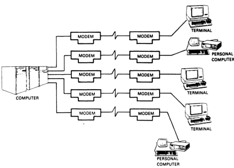
The original method for linking several devices at one site to a computer at another site is shown in Figure 1-1. Each device
requires its own telephone line and two modems, one at each location. In the illustration, a total of ten modems and five separate telephone lines are required. Phone line usage is ineff ic ient and costl y in te rms of monthly charges. Al so, the large number of modems represent a high purchase or monthly rental expense.
Multiplexers solve the cost problem of multiple modems and phone lines otherwise required to connect several remotely located terminals to long distance or local area networks.
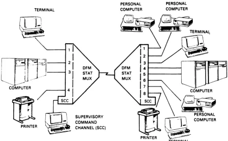
The DFM system can replace the configuration of Figure 1-1 wi th both reduced costs and greater efficiency. Two DFM units, two modems, and one high-speed telephone line (Figure 1-2) can service multiple terminals as well as provide other valuable network management benefits.
The DFM unit monitors the usage and performance of each channel as well as the concentrated link. It can print or display error counts and statistics on utilization for each channel or the link.
Additional cost savings and efficiency are realized because the DFM Intelligent Communications Processor (ICP) is an intelligent interfacing device. The DFM unit connects previously incompatible devices, provides automatic error correction, and manages the entire network from one location.
COMPUTER
PERSONAL COMPUTER
TERMINAL
~
~~PERSONALCOMPUTER
ra
TERMINAL [image:15.615.55.525.82.419.2]TK·10651
TERMINAL
@.
I-",
,, ,
i
PRINTER
SUPERVISORY COMMAND CHANNEL (seC)
PERSONAL COMPUTER
@
PRINTER
rr=Q, --}-,
~
TERMINALFigure 1-2 DFM
rcp
Commun ication Network [image:16.613.90.558.92.382.2]1.2 DFM FEATURES
A conventional multiplexer channel can communicate only with devices attached to the same channel on the remote unit. This type of operation is called dedicated. Other devices cannot access a dedicated channel even when it is inactive.
The DFM ICP eliminates the limitation of dedicated channels by allowing any channel in the network to be connected to any other channel. Multiple channels at one location can contend for a
limited number of computer ports or other facilities at the other end of the system. Channel switching and port contention provide the flexibility that is required in today's rapidly changing communications environment.
The modular design permits quick and easy removal or insertion of modules into the backplane. No tools are requi red, which speeds troubleshooting, simplifies field upgrades, and decreases down time for maintenance.
DFM flexibility is a key feature. Programmable configuration options adapt the units to most types of data communications requirements and independent channel configurations allow the units to interface between nearly any type of bit serial devices. The DFM unit supports both synchronous and asynchronous communications traffic. Two out of every group of four channels can support either Digital Equipment Corporation's DDCMP or other synchronous protocols. Synchronous protocols other than DDCMP are handled in a transparent mode.
1.2.1 Channel Switching and Port Contention
DFM handling of switched channels allocates valuable computer ports more efficiently, services a greater range of hardware facilities, and provides easy expansion to support additional users.
Switched channel ends are treated independently. A device connected to a switched channel on the local unit may communicate with any device connected to the local or remote unit. If a selected channel or all channels assigned to a group are busy, the request for connection is queued. The connection is made as soon as the requested channel or any other channel assigned to the same group is available.
The contention feature of switched channels enables sharing of a limited number of computer ports or other facilities among a var iety of users. Thi s feature allows a l6-channel uni t to be connected to a uni t wi th fewer ports, wi th channels at one end contending for connections on a first come, first served basis.
1.2.2 Network Management and Control
Management of the DFM system is accomplished through interactive
commands that are entered ~o the system through the supervisory
channel. Programming, diagnostic testing, and monitoring of the system are accomplished by the supervisory command program, which
is directly accessed by the supervisory channel. If desired, t~e
supervisory channel can be dialed into from a remote location.
Nondisruptive, current data information can be disPlared or
printed by the supervisory channel using the monitor capab lities for channel, link, or system. Monitored information for channels includes four types of error counters, EIA signal status, the last
characters transmitted and received by the terminal, and
transmit/receive utilization statistics.
Monitor information for the link and system includes link error counters, EIA signals, link transmit/receive utilization, and system status indicators.
This vital information enables the user to analyze data traffic
trends and potential congestion points. It also isolates the
location and nature of error conditions. For example, widely
fluctuating link statistics can provide an early warning of
telephone line failure. When telephone line performance is
questionable, link categories can be monitored (and printed out) over time to help define a link problem before it causes the
system to go down. A full range of diagnostic tests quickly
isolates malfunctioning components to replaceable modules.
Supervisory Channel
The supervisory channel provides direct access to the
supervisory command program, which processes DFM interactive commands. The supervisory command program may also be accessed from the data channels once they are enabled to do so by the
system manager. Supervisory channel output takes full
advantage of CRT display capabilities, displaying a full screen of system information on request.
Down-line Loading of Parameters
When units are reset, reinitialized, or reconnected, channel
parameters are checked for consistency and down-line loaded, if necessary. This not only ensures parameter compatibility between units, but also speeds the initial configuration
process. Channel parameters need to be entered on only one
Selective Modem Control
The integral modem module permits switch selectable modem control and single source support of the DFM system. When the front panel signal quality monitor indicates signal deterioration, the user may manually initiate a fallback io transmission speed.
Parameter Protect
The front panel parameter protect switch protects current configuration of parameters from being changed either by command or down-line loading. This prevents either accidental or deliberate tampering with system parameters from a remote location once the system is set up.
Simple Programming Dialog
Interactive commands make supervisory functions easy. DFM command structure includes prompting that helps first-time users through each step of a complete command. Experienced users can use abbreviated commands to speed the process.
Nonvolatile Storage
DFM option settings are stored in NVROM (nonvolatile read only memory), which is not disturbed by loss of power. Thus, units do not have to be reprogrammed if a power interruption occurs.
Password Secured Access
Passwords assigned and changed only by the system manager limit the use of supervisory and data channel command modes to authorized users only. There are two levels of password access: user and system manager.
The USER level allows access to noncritical functions such as monitoring status, displaying configuration parameters, executing limited test functions, and normal data channel usage via the CONNECT/DISCONNECT commands. The SYSTEM MANAGER level allows access to all command functions.
Autodisconnect
1.2.3 Intelligent Interfacing
Channels may operate synchronously or asynchronously using 5-, 6-, 7-, or a-bit data with even, odd, or no parity, and anyone of thirteen flow control conventions. In addition, the DFM unit provides the following for each channel:
Speed Conversion
Channel ends may be programmed for different speeds allowing terminal devices to communicate with one another, regardless
of differences in speed. This is especially convenient in
applications using switched channels.
Flow Control Conversion
Flow control conventions are separately programmed for each channel end. The intelligent interface provided by the DFM unit automatically translates flow control types between ends. Incompatible devices now can be connected by taking advantage of this feature. For example, a computer using XON-XOFF flow control can be connected to a printer that uses DSR-DTR, and the DFM system ensures that data is stopped and started as required by either device.
Autobaud
Autobaud automatically adjusts the multiplexer data rate to
match the speed of the connected terminal. It does this by
determining the speed of the first character received
(expected to be a RETURN). This feature is a necessity when
DFM channels are connected to dial-up modems since the
transmit speed of the terminal may be an uncertainty. Autobaud also may be used on channels directly connected to terminals.
Break Character Control
Break characters are accepted by the DFM unit and reproduced
at the other channel end. Accuracy is crucial because some
data terminals have functions associated with break characters of different lengths.
Flyback (Fill) Character Delay
1.2.4 Comprehensive Diagnostics
Pinpointing failures is made easy by the automatic self-tests and diagnostic tests available to data channel operators or the system manager.
Power-up Self-test
Built-in self-test diagnostics are executed when the units are powered on or restarted from the supervisory channel. They
detect most hardware failures. LED error codes identify the
failure and location.
System Manager Level Tests
Diagnostic test capabilities including Channel Loopback, Link Loopback, Remote Echo, Local Echo, and Pattern tests are available to the system manager. Tests are executed from either the supervisory channel or any properly enabled data channel.
Data Channel Level Tests
Data channel command mode allows a limited subset of tests to
be run without having to enter a password. Local Echo, Remote
Echo, Channel Loopback, and Pattern tests may be run on any channel that is in command mode.
Manual Maintenance Mode
When the supervisory channel is inoperative or not available, a subset of testing features may still be run by using the two maintenance pushbuttons (Ml and M2) on the control module. Front panel LEDs indicate test results.
1.2.5 Expansion Capability
Modular Design
Simplicity of design enables tool-free access and module change by quick removal and reinsertion into the backplane. Failures are quickly isolated to a replaceable module. All LEDs and pushbutton swi tches are readily accessible on the front panel.
Expansion Line Modules
Channel capacity can be increased in A-channel increments, up
to a maximum of 16 channels. Of each 4-channel group, two
Integral Modem Module
For complete system independence and single-source support, Digital Equipment Corporation provides several integral modem modules available in 2400 bits/s, 4800 bits/s, or 9600 bits/s. Modem control, testing, and moni toring are made easy by the use of front panel switches and LEDs.
1.2.6 Maximized Throughput
DFM design and functions optimize both response time and link utilization (throughput):
Multi-microprocessor Design
The DFM uni t has up to four microprocessors that perform a
variety of independent processing tasks. The control module,
channel modules, and integral modem module have their own microprocessor(s). This distributes the workload and optimizes
microprocessor time, which maximizes throughput and
performance.
Internal Direct Memory Access (OMA) Data Transfer
Control board log ic transfers data directly between channel
and link, relieving the processor of this task. This
increases overall processing capability and provides
exceptional throughput and response time.
Channel Input and Output Buffers
Each DFM channel has input and output buffers. Each buffer
has a capaci ty of 4K bytes for synchronous channels and 2K bytes for asynchronous and swi tched channels. Separation of buffering, aids link throughput and minimizes the possibility of buffer overflow.
Error Correction
The DFM system provides automatic correction of errors that
occur during data transmission. A cyclic redundancy check
(CRC) is run on each block of data as it is transmitted and
received. Any discrepancy results in an automatic request for
retransmission. The CRC method guarantees an undetected error
1.3 APPLICATIONS AND CONFIGURATIONS
The versatil i ty of the DFM uni ts enable them to support a large variety of applications. Computers can be used at either or both ends of the link, as well as any mix of printers, terminals, personal computers, or moderns. Swi tching and contention features pe rm i t a si ng 1 e un i t to be used as a local equi pmen t allocat ion device. Configurations of the DFM system include support for:
• Channel switching and port contention
• Single-unit use of switching functions
• Tail circuits (either dial-up or dedicated modems connected to a remote DFM port)
• Dial-up computer timesharing
• Communications via satellite
• Both asynchronous and synchronous traffic
• Multiple DFM configurations
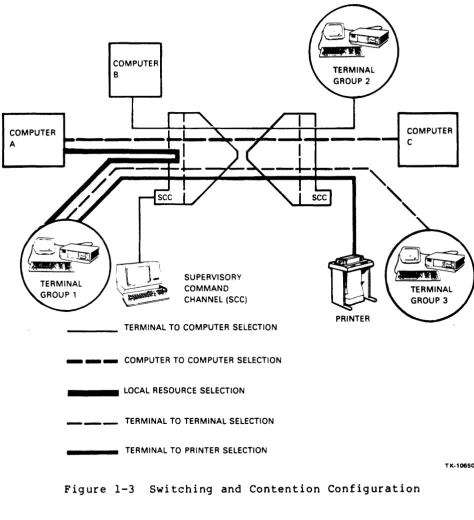
1.3.1 Switching and Contention
Channel switching and contention features provide the flexibility required in the rapidly changing data communications environment. Any switched channel end can be connected to any other, if allowed by the security feature. This makes it possible for a user to have immediate access to all authorized company facilities (see Figure
1-3) •
The channel contention feature allows a unit at one end of the network to be connected to a unit with fewer channels at the other end. Terminals at one end contend for connections on a first corne, first served basis. Inactivity for a time period selected by the system manager results in an automatic disconnect, freeing unused computer facilities.
COMPUTER A
COMPUTER B
I
l
-j _\
SUPERVISORY~~ ~~ COMMAN 0 ~ CHANNEL (SCC)
TERMINAL TO COMPUTER SELECTION
_ _ _ COMPUTER TO COMPUTER SELECTION
_ _ _ _ LOCAL RESOURCE SELECTION
TERMINAL TO TERMINAL SELECTION
TERMINAL TO PRINTER SELECTION
PRINTER
COMPUTER C
TK-10650
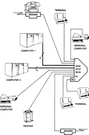
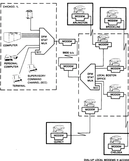
[image:25.615.55.530.82.602.2]There are circumstances in which a large number of users require connection to a variety of in-plant facilities, or a limited number of computer ports need to be shared locally by many users. In such an application, a single unit may be used as a local
swi tch (see Fig ure 1-4). By us i ng the simple CONNECT command,
users are either connected or queued for connection to the desired facility.
COMPUTER 2
PERSONAL COMPUTER
COMPUTER 1
4
PRINTER
TERMINAL
5
PERSONAL COMPUTER
TERMINAL
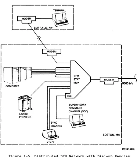
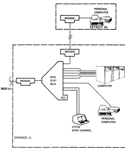
[image:26.623.150.490.178.690.2]1.3.2 Tail Circuits
Figure 1-5 illustrates a network configuration with DFM sites in
Boston and Chicago, each having a substation (called a tail
circuit). Each tail circuit connects to the DFM unit by modems
using either public switched telephone facilities or private
leased lines. Notice in Figure 1-5 that each DFM site has a
variety of channel devices.
COMPUTER
- - - ,
TERMINAL
I
QI
~~~Y_-_---1
- - - .
SYNC CHANNEL
~
SUPERVISORY COMMAND CHANNEL (SCC)
Q
I
I
I
I
BOSTON, MA
I
L _____
~~_ _ _ _ _ _ _ _
I
MKV~76
Figure 1-5 Distributed DFM Network with Dial-up Remotes
9600 b/s
I
I
I
I
I
I
I----~E:::_--,I
I
COMPUTERI
MODEM~."
I
~~I
L ____
DET-R.2!.!:~-.JVT278
SYNC CHANNEL
PERSONAL COMPUTER
I
CHICAGO, ILL _ _ _ _ _ _ _ _ _ _ _ _ ~
TK·10649
Figure 1-5 Distributed DFM Network with Dial-up Remotes (Sheet 2 of 2)
[image:28.624.116.525.106.604.2]IcHI~GO~ - - -
-~,I'
l-=2
!
~l
'I
I=;JD~
J~
I
COMPUTER,
I
9600 btsI~~
'-...;;;;::::.
I
PERSONALI
COMPUTER:n~.
I
I
~~.I
.-,' "
SUPERVISORYI
( l - COMMAND
,
\~~
CHANNEL (SCC) ,TERMINAL ~
L_~
_ _ _ _ _
QUINCY
I
I
L _____ _
CHELSEA DIAL-UP LOCAL MODEMS = ACCESS TO LONG DISTANCE CPU
MKV84-Q286
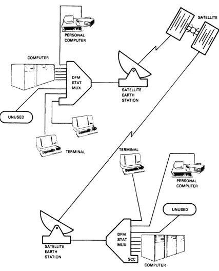
[image:29.615.64.517.80.648.2]1.3.3 Satellite Links
DFM network configurations are not limited to conventional terrestrial link facilities. Concentrated link facilities can include microwave, fiber-optic, or satellite components. Figure 1-7 illustrates the use of a satellite link instead of a telephone
line.
COMPUTER
PERSONAL COMPUTER
'---IT]
~
Q.
TERMINALSATELLITE EARTH STATION
EARTH STATION
rrT-l.
1-~
COMPUTER
PERSONAL COMPUTER
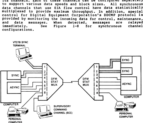
[image:30.615.111.538.161.689.2]1.3.4 Synchronous Channels
The DFM uni t handles synchronous data traffic on up to one-half its channels. Each of these channels can be configured separately
to support various data speeds and block sizes. All synchronous
data channels that use EIA flow control have data statistically multiplexed to provide maximum throughput. In addition, special. control for Digital Equipment Corporation's DDCMP protocol is provided by monitoring the incoming data for control, maintenance,
and data messages. When detected, messages are relayed
immediately. See Figure 1-8 for synchronous channel
configurations.
VT278 SYNC
SYNC
ASYNC ~_-.J
PERSONAL COMPUTER
~l
-,
SUPERVISORY _ COMMAND _ CHANNEL (SCC)~.
1---....
ASYNCCOMPUTER
~
PERSONALCOMPUTER
TK.108S7
Figure 1-8 Synchronous Channel Configuration
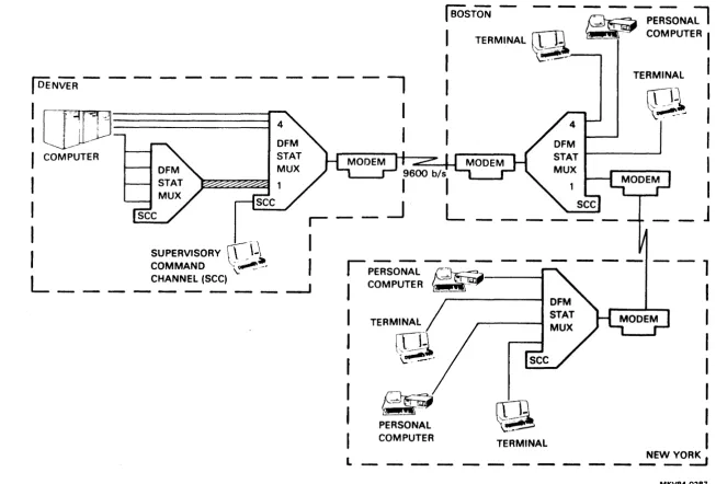
1.3.5 Multiple DFM Configuration
[image:31.612.48.525.108.520.2]I
DENVER - - - --: [][IJ---I
I
COMPUTERI
---,
I
I
I
BOSTON - - -~
~E;;NA;l
I
TERMINAL~
~""'9""
COMPUTERI
I
.'--
I
TERMINAL
:
~l
:
I
I
~~~~
I
I
I
-I
-\
I
I
__ J
I
SUPERVISORYCL
\~1.
COMMAND ~-.
I
L ____
C~NEL (SCC) _ _ ---.Jrp"E;SO-;;-L ~ - - -
- - 1
I
COMPUTER , -I
TERMINAL
PERSONAL COMPUTER
~
'(~I
I
I
I
I
TERMINAL
I
NEW YORK
L _ _ _ _ _ _ _ _ _ _ _ _ _ ~
[image:32.794.57.710.74.515.2]2.1 GENERAL
CHAPTER 2 PREINSTALLATION PLANNING
This chapter provides guideline information for planning DFM installations. This information is to help determine what additional equipment will be required to satisfy your application requirements. The latter portion of the chapter provides cross-reference data for determining placement of the uni ts, cabl ing, and other requirements.
2.2 SUPERVISORY CHANNEL
Use of the independent supervisory command channel (SCC) is required during initial installation to set up the system parameters, which are described in Chapter 6. Once the system is set up, the terminal may be moved to a data channel where it may alternatively be used for supervisory purposes. In most cases, once the system is set up, there is little need for supervisory access.
The SCC terminal should be located within 15.24 m (50 ft) of the DFM unit for a direct connection. For distances greater than 15.24 m (50 ft), line drivers, modems, or a dial-up connection may be used.
Terminals connected to the supervisory port must be asynchronous, and set to some combination of the following:
• Seven or eight bits
• Parity of even, odd, or none • One stopbit
• Flow control of either XON-XOFF or none
• Speed of 150, 300, 600, 1200, 2400, 4800, or 9600 bits/s
The supervisory channel is equipped wi th an autobaud mechanism that allows it to adjust to the current speed setting of a terminal when it is connected. Autobaud can detect speeds of 150, 300, 600, 1200, 2400, 4800, or 9600 bits/s.
There are three levels of system control:
• Supervisory Level -- This level is the highest level of system control and requires a password. The supervisory level password allows the system manager total supe rv i-sory capability. This level displays a SYS> prompt.
• User Level -- This level also requires a password, but is more restrictive, not allowing parameter changes or test
functions. This level displays a USR> prompt.
• Channel Operator Level -- This level allows channel users to perform tasks necessary for their channels only, without a password. This level is available only to channels that have been enabled via the supervisory level. This level displays a SEL> prompt.
2.3 CHANNEL CONSIDERATIONS
2.3.1 Channel Type
Channel type parameter allows the DFM unit to support the communications protocol of devices connected to the selected channel. Choices are:
•
Asynchronous,•
Switched,•
DDCMP,•
Synchronous, and•
Unused.2.3.1.1 Asynchronous Channels Asynchronous channel types operate with asynchronous protocol, and are dedicated. For example, a dev ice connected to Channel 1 on the local uni t can only communicate with whatever device is connected to Channell on the remote unit.
2.3.1.2 Switched Channels -- Switched channel types operate with asynchronous protocol, but can be connected to any other switched channel via the CONNECT command (see Chapter 5). Switched channels are completely independent; Channell on the local unit may be connected to any other switched channel on the local unit as well as any switched channel on the remote unit (see Channel ID and Group Access Options, Chapter 6).
If Channell's request is the first one queued, it will be connected as soon as Channel 3's current connection is terminated. Otherwise, it must wai t until prior requests for connection are satisfied. Channels requesting connection to busy channels or groups remain queued until either a connection is made, or the request is withdrawn with the DISCONNECT command.
2.3.1.3 Synchronous Channels -- Synchronous channels are defined as either DDCMP or sync channel types. DDCMP is Digital Equipment Corporation's proprietary protocol used primarily with systems joined by DECnet facilities. Synchronous channel types support any type of synchronous communications protocol in a transparent manner (that is, the DFM unit does not look at or interpret data on the channel). Because of internal buffering, however, some delay in the data transfer may be experienced.
Since constant commun icat ion between dev ices is a pa rt of most synchronous protocols, synchronous channels have a big impact on link utilization. Data rate calculations for the link must include 120% of the combined data rates for full-duplex syn9hronous
channels. For DDCMP and half-duplex synchronous operation, the
link calculations must include 50% of aggregate input.
Half-duplex operation is recommended
synchronous (non-DDCMP) channel types. selected by CTS-RTS flow control.
whenever possible for
Half-duplex operation is
DFM handl ing of the DDCMP protocol el iminates the need for flow
control or half-duplex operation. In DDCMP protocol, when the DFM
unit detects an "idle" frame (no data present), it does not
transmit it. This saves concentrated link bandwidth for frames
with data.
Synchronous channel loading must be spread evenly among channel modules. For this reason, the DFM unit only supports synchronous or DDCMP operation on two out of every group of four channels (Channels 1 and 2, 5 and 6, 9 and 10, and 13 and 14). The load should be spread as evenly as possible. For example, if 3 synchronous channels are required on a l2-channel unit, they
should be assigned to Channels 1, 5, and 9.
Since synchronous communications protocols typically include their own error detection and retransmission schemes, the DFM unit does not provide error correction on synchronous and DDCMP channel types.
Section 2.4.2 covers link speed
synchronous channel considerations.
2.3.1.4 Unused Channels -- Channels not currently in use may be set to a channel type of unused. This prevents the channel from being serviced by the DFM unit, reduces system overhead, and improves service to the remaining channels. Channels may be changed from one of the other types to unused and then back, without losing parameter settings.
2.3.2 Connecting a DFM Channel to a Modem
Either dial-up or dedicated modems may be connected to a DFM channel. For 12~~ bits/s dial-up capability, the 212A compatible DFl12 modem is available. For 24~~ bits/s operation, the DF124 or DF224 modems are available.
A crossover cable (BC22M cable or equivalent) must be used to connect a modem to a DFM channel. When a dial-up modem is used, it is possible to have the host computer or the DFM uni t manage the handshaking sequence. (See Section 6.7.2 for more info rmat ion.)
Synchronous and DDCMP channels can be dialed into only if a modem with an auto-answer feature is used; carrier detect (CD), data terminal ready (DTR), and clear to send (CTS) are always asserted on synchronous and DDCMP channels.
2.3.3 Channel Cabling
Regardless of the channel type setting, straight-through cables are used for connection directly to terminals, and crossover cables are required when a DFM channel is connected to a modem. Further information on DFM cables is found in Table 2-1. Cable wiring diagrams are found in Appendix C.
2.4 LINK CONSIDERATIONS
The first consideration for the link is to determine what type of facility will be used. The following sections discuss link types, then suggest a procedure for determining link speed. Having determined the required data rate for the link, it is possible to determine requirements for direct or modem connections. This, in turn, establishes cabling requirements.
2.4.1 Type of Link
A communications link can be anyone of the following:
• Dial-up phone line with modems;
• A leased (or dedicated) line with modems;
• Microwave or satellite transmission service ,(typically accessed through phone connections); or
With dial-up phone lines, data is sent through the telephone company's regular voice grade I ines and intermediate swi tching
circuits. At times, noise and interruptions on these lines can
make effective data communications difficult, if not impossible.
Leased lines are physically separate circuits that are not shared with other users. A leased line is available at all times and can achieve high-speed transmission in both directions simultaneously
by employing a 4-wire circuit. In addition, the monthly charge
for leased lines does not vary with hours of usage as it does with dial-up lines. Under some circumstances, however, even dedicated leased lines experience noise interruptions and line -hits,- which may lead to garbled data transmissions.
Two other forms of transmission media are becoming increasingly popular:
• Microwave, and
• Satellite.
Both provide high-speed, high-volume data communication. Microwave
links are particularly effective for intracity applications,
satellite links offer effective overseas and intercity
connections.
When data communications capabilities are needed for more than a few hours each business day, a dedicated phone line is usually the
most economical solution, even for one terminal. If there are
several terminals in use at the same time and location, the user will need a dedicated line to take advantage of the cost savings of multiplexing with the DFM unit.
All cables used as part of the concentrated link should be of ~igh
quality construction, preferably shielded twisted palrs.
Specifications for cables used as part of the concentrated link are described in Appendix C. The characteristics of the signals on the concentrated link as well as channel lines are covered in Appendix E.
2.4.2 Data The proper application performance handle the because of facilities.
Rate for the Link
data rate (speed) of the concentrated link in any
is an important factor in achieving optimum
Link speed is determined by:
1. Dividing channel devices into categories
a. Asynchronous CRTs with flow control b. Asynchronous CRTs without flow control c. Asynchronous block mode CRTs
d. Printers
e. DDCMP or half-duplex synchronous devices f. Full-duplex synchronous devices
2. Estimating a "required bandwidth factor" for each category
a. Async with flow control
=
.15 b. Async without flow control=
.25 c. Async block mode CRTs=
.30d. Printers
=
.35 to .6e. DDCMP, half-duplex sync
=
• 50f. Full-duplex synch
=
1.23. Multiplying the combined baud rates of each category times the required bandwidth factor
For example, suppose there are four asynchronous CRTs (using flow control) operating at 4800 bits/s:
Combined baud rates
=
4800X
4=
19,200 bits/s 19,200X
.15=
2880 bits/sThus, 2880 bits/s of link speed is required for these devices. Suppose there are also two DDCMP channels operating at 2400 bits/s:
Combined baud rates
=
2400X
2=
4800 bits/s 4800X
.5=
2400 bits/s2400 bits/s of link speed is required for these two devices.
The bandwidth factors listed are estimates only, based on average conditions and usage. Additional factors may require that these
estimates be revised either upward or downward. For example, if
an asynchronous terminal using flow control is planned for a very light usage application (one or two hours a day) the required bandwidth factor for that device may be lowered to .1B.
On the other hand, if the same terminal is to have an unusually heavy application, it is advisable to increase the bandwidth factor to .20.
In general, bandwidth factors should not vary much from the preceding figures. In the case of printers, however, the amount of usage can significantly alter the estimate given.
When a printer receives data at full capacity, it will tend to monopolize the link for the duration of the job. Thus, if a printer will be running for more than 10 or 15 minutes each hour, a factor of .6 (or greater) may be warranted. If it is going to be running only a few minutes each hour, a factor of .35 to .4 probably will be sufficient.
For asynchronous block mode terminals, the factor to be used is dependent on the size of the block, even when flow control is in use. This is because the CPU usually will not respond to flow control except between blocks of data. If the size of the blocks is not too big (for example, fewer than IB00 bytes), the suggested factor of .30 should be adequate. Otherwise, like a printer, terminals will monopolize the link for the duration of the block, and the factor required should be increased proportionately.
Flow control usually increases the response time to remote
devices. Since the DFM units regulate the flow of data, however, data will not be lost. Without flow control, as the speed of the concentrated link is reduced, the chance of buffer overflow and subsequent loss of data is increased.
When an error is detected, the DFM unit automatically retransmits data. Thus, a higher error rate directly reduces the effective
throughput of the concentrated link. If phone lines are known to
be troublesome, the estimated link speed should be increased
accordingly. In general, the larger the network, the more
conservative the estimate of link speed should be.
2.5 LINK MODEMS
The DFM unit can operate with either a variety of standalone external modems such as the DFl00 series or a variety of optional integral modem modules.
2.5.1 Optional Integral Modem
The DFM enclosure supports an optional integral modem module of either 9699, 4809, or 2499 bits/s, allowing complete system
independence and single-source support of the DFM system.
While the DFM unit can work in conjunction with nearly any type of modem, the DFM integral modem is the ideal match. The integral modem is a self-equalizing, synchronous modem designed for point-to-point applications. Self-equalization allows them to adjust automatically to changing line conditions, which means that they operate effectively over standard, unconditioned voice grade lines
(type 3992).
2.5.2 External Link Modems or Line Drivers
If external modems are used, they must meet two primary criteria:
• They must handle control signals in a way that allows the DFM uni ts to detect an interruption to communications
(for example, by dropping CTS).
• They must be data transparent; that is, they must not be dependent on the communications traffic being in character format.
The DFM unit can operate with synchronous moderns of any speed up to 19.2K bits/s. The only asynchronous link speed that is supported, however, is 9600 bits/s. Currently, the only type of asynchronous modern that is as fast as 9600 bits/s is a short haul modem.
If DFM units are to be a maximum of 15 to 20 miles apart, it may be possible to utilize short haul, asynchronous moderns operating at 9690 bi ts/s. Check manufacturer's requi rements for distance, and other requirements such as conditioning of the telephone line.
For interplant applications, the DFM units may be either directly connected, or connected with line drivers. Digital Equipment Corporation recommends a maximum of 15.24 m (50 ft), in accordance with EIA standards, for units to be directly connected. With high quality cable and the absence of any electrical interference, it may be possible to go farther than 15.24 m (50 ft).
Line dr i vers are used in conj unction wi th in-plant cables up to approximately 1524 m (5000 ft). They amplify the input digital signal so that longer distances can be covered without signal deterioration. Check manufacturer's requirements for distances and
Table 2-1 summarizes cable types and usage in conjunction with the various kinds of communication facilities.
2.6 OPERATING CONDITIONS FOR THE DFM UNIT
The DFM unit is designed to operate in a clean and dry environment
such as a computer room or office area. It is lightweight and can
be placed on any solid, unheated surface such as a shelf br
desktop. Do not place the unit on top of a cabinet that generates
heat. The DFM unit may also be located in the H9646 communications cabinet on an optional louvered shelf. Clearance on the sides of the unit is not important. Avoiding obstruction of the bottom and top ventilation holes, however, is very important.
CAUTION
Do not block top or bottom ventilation holes. Convection is the only method of
cooling the unit. If ventilation is
restricted, damage will result.
About 10.16 cm (4 inches) of clearance at the rear is required for
cable connection and routing. The front of the unit should be in a
position that makes the front panel LED indicators clearly
visible.
2.6.1 Environment
TheoDFM unitooperates within temperatures ranging from 00 to 400C
(32 to 104 F) and relative humidity ranging from 0% to 95%
noncondensing up to an altitude of 2438 m (8000 ft). Storage
(nonoperating) temperatures are from -350 to 7loC (-30° to l600F).
2.6.2 Power Requirements
Nominal power required for the DFM unit is 115 Vac (230 Vac optional) within the 50 to 60 Hz frequency range at 92 W. The DFM
uni t is Underwri ter' s Laboratory (UL) listed and Canadian
Standards Association (CSA) approved. The power cord is 2.1 m (7
ft) long.
2.7 PREINSTALLATION TEST AND FAMILIARIZATION
A pre installat ion benchtest (Chapter 3) is recommended for each
pair of DFM units prior to installation at local and remote sites. The purpose is both to ensure that the units are functioning
properly, and to familiarize operators with their use. For this
reason, it is strongly recommended that both DFM units be sent to the same site.
When integ ral modems are purchased, uni ts are connected for the test with a piece of phone wire or any other compatible 4-wire
cable. If integ ral modems are not purchased, Dig i tal Equipment
2.8 DFM CABLES
Figure 2-1 shows the locations of the various cables required with the DFM system. Table 2-1 provides cable descriptions and order numbers.
Each channel presents a DCE interface which can be directly connected to a terminal (DTE), in which case, a straight-through. cable is used. If a channel is connected to a modem (DCE), a crossover cable must be used.
The link (connector J18) presents a DTE interface, expecting to be connected to a modem (DCE). If units are to be directly connected
(DTE to DTE), a crossover cable must be used.
ASYNCHRONOUS OR
SWITCHED
0
CABLE E~~
CHANNEL 1 CHANNELDEVICE CHANNEL 2
CHANNEL 3
CHANNEL 4
CHANNEL 5
CHANNEL 6 SYNCHRONOUS OR
DDCMP
EJ
CABLE FIf
CHANNEL 7 CHANNELDEVICE CHANNEL 8
CHANNEL 9
CHANNEL 10
PRINTER
EJ
CABLE En
CHANNEL 11 DEVICECHANNEL 12
CHANNEL 13
DIAL-UP TAIL CHANNEL 14 CIRCUIT CONNECTS
TO CHANNEL 16 CHANNEL 15 DEVICE VIA MODEM
..si1
MODEM~
B
CABLE M CHANNEL 16 SUPERVISORY
COMMAND
EJ
CHANNEL (SCC)B
CABLE E
El
El
~
~
E1
0
EJ
0
~
~
~
E1
~
0
E1
EJ
USE CABLE F FOR EXTERNAL MODEM LINK; FOR SYSTEM PRETEST CONFIGURATION, USE CABLE L
[!}--B
~MODEM;tL-USE STANDARD 4-WIRE TELEPHONE CABLE FOR DFM
INTEGRAL MODEM CONNECTIONS
MKV85·2OQO
[image:42.613.56.516.240.669.2]