2018 2nd International Conference on Modeling, Simulation and Optimization Technologies and Applications (MSOTA 2018) ISBN: 978-1-60595-594-0
A Comparison Research into Characteristic Waves of the Well Hole II
Interface Cement Part Missing Sound Field
Dan-yan XIE
1,*, Jin QIAN
2and Wei YANG
3 1,2Taizhou University, Taizhou, China
3
Nanjing Yunduopu Network Co., Ltd., Nanjing, China
*Corresponding author
Keywords: The sector missing, The bow missing, The characteristic wave amplitude.
Abstract. Due to construction process and gravity, it forms a part missing in the cased hole cement ring during cementing. For example, in a vertical well, it often forms sector missing parallel to the well axis, or it forms bow missing in the upper layer cement ring of the horizontal well. These part missing are different from traditional cement ring circumferential missing. Study on the relationship between the II interface characteristic wave amplitude and the missing angle in the vertical well or the bow missing in the cement ring upper layer of the horizontal well. It shows that the larger the amount of part loss, the larger the first wave amplitude, which is equivalent to the thickness of the water layer in the circumferential loss. This study helps to establish a quantitative distribution law of part deletions.
Introduction
In order to ensure the normal implementation of oil recovery operations in the oil field, it needs cementing to fill the cement between the casing and the stratum. There is a lack of cement in some locations because of cementing operations. This is called a channel. The presence of the channel causes destruction to the axisymmetric structure of wellbore and seriously affects the normal operation of the well. In order to detect the presence of a channel and its size and position, studying the sound field of casing well with channel is necessary. In the traditional channel problem research, no matter analytic method or numerical calculation method is applied, it’s assumed that the cement layer is completely off, in the assumption that there is a 360 ° channel. However, this is not consistent with the actual situation. For example, it forms a sector channel parallel to the shaft axis in the vertical wellbore[1-4], or forms bow missing in horizontal well cement ring upper layer[5,6].
The current common researches focus on the separate study of sector missing or bow missing. There isn’t a comprehensive study of these part missing. In fact, although the vertical and horizontal well structures differ greatly, from the influencing factors of part missing. The two channels have their own characteristics and certain similarities. This paper wants to study the characteristic wave propagation characteristics of the II interface part channel which the vertical well II interface sector cement missing or the horizontal well bow cement missing.
Numerical Simulation Method for Part Cement Missing
The Part Cement Missing Model
The cross section of vertical well axis is as shown in Figure 1.The medium from the inside to the outside in turn represent the borehole fluid, steel casing, cement ring, formation in the well. Figure 1 (a) is II interface sector missing in vertical wells. h represents the thickness of the channel water layer. Figure 1 (b) is the bow cement missing in horizontal wells. h represents the channel water layer height. When h is less than the cement ring thickness 30mm, indicates that there is a channel in the II interface of the wellbore.
Figure 1. (a) The II interface sector missing in vertical wells (b) The bow cement missing in horizontal wells.
High – order Staggered 3-D Finite Difference Method
Use 3-D finite difference method based on stress - velocity to solute first-order partial differential equation of wellbore sound field, as shown in Eq. 1.
z y x t v z y x t v z y x t v zz yz xz z yz yy xy y xz xy xx x z y x f f f ) y x ( t ) x z ( t ) y z ( t z 2 ) z y x ( t y 2 ) z y x ( t x 2 ) z y x ( t xy xz yz zz yy xx x y z x z y zz z z y x yy y z y x xx x z y x v v v v v v g v v v v g v v v v g v v v v (1)
It uses a staggered grid difference format to improve the computational efficiency. It use 2 -order difference in time, and use 8-order difference in space. The finite difference simulation results need to satisfy the convergence and stability, and the time step of stability as shown in Eq. 2.
2 2 2 max 0 . 1 z y x v
t (2)
And the convergence of the spatial interval as shown in Eq. 3.
max min 4 ) , , max( f v z y
x
[image:2.595.72.486.408.621.2]max
v and vmin represent the maximum and minimum sound velocity of the medium, and fmax
represents the highest effective frequency of the sound source.
In the 3-D finite difference simulation, exist the false reflection of man-made boundary because of limited computing space, and use the non-cracked perfect matching method (NPML) to weaken this boundary reflection [11].
The Parameter
Sound source uses Gaussian sine wave in this paper, the center frequency is 18 kHz and bandwidth is 6 kHz. Casing radius is 0.06285m and Casing wall thickness is 0.007m. The parameters in the wellbore are shown in Table 1.
Table 1. The material parameters.
media P - wave
velocity (m/s)
s - wave velocity (m/s)
density (kg/m3)
well fluid 1580 0 1090
steel casing 6098 3354 7500
cement layer 2800 1700 1920
Fast formation 3800 2200 2600
Slow formation 3000 1765 2261
Study on the Characteristic Wave of the Part Missing Sound Field
Study on the Characteristic Wave of Sector Cement Missing in the Vertical Well
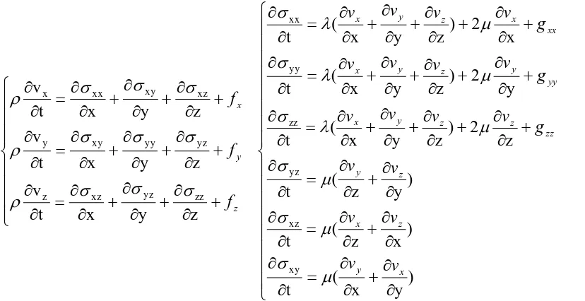
[image:3.595.95.493.632.744.2]Study on the effect of the missing angle of the II interface to the first wave amplitude and the travelling time of the characteristic wave. Calculate the sound field of the models with a sector angle of 15°, 30°, 45°, 90°, 135°, 180°, 270°, 360° (consistent with the calibration well) and a water layer thickness is 10.0 mm. In order to determine the first wave attribute, calculate the sound field of the fully cementation model and 360 ° missing model, as shown in Figure 2. The 360 ° missing amplitude is significantly smaller than the amplitude of the fully cementation. At the same time, it is found that the first wave travelling time of the 360 ° missing is about 0.475ms (peak),and the first wave travelling time of the full cementation is about 0.525ms. The first wave travelling time of the 360 ° missing is slightly faster than the full cementation. This is due to the fact that the first wave of 360 ° missing is the II interface characteristic wave, and the first wave of the fully cemented is stratum wave. Therefore, the first wave in Figure 2 should be II interface characteristic wave. The distribution pattern of the first wave amplitude and the travelling time change with missing angle as shown in Figure 3. The first wave amplitude of the II interface characteristic wave increases with the increase of the missing angle. That means, as the cementing quality deteriorates, the first wave amplitude of the characteristic wave gradually increases. The characteristic wave travelling time has little to do with the missing angle.
Figure 2. The sound field of different missing angle (P - wave velocity is 3800m/s,the fluid ring thickness is 10.0mm)
peaks, it can be seen from Figure 3(c) that when the thickness of the fluid ring is 1.0mm,5mm,10mm, the amplitude of the first wave of the characteristic wave increases as the cement missing angle increases. When the thickness of the fluid ring is 15mm, there is a small change in the missing angle of about15 °. The reason may be that the amplitude of the characteristic wave is interfered by other factors when the missing angle is too small or the missing thickness is too small. The overall distribution law is still increasing with the first wave of the characteristic wave as the angle of cement missing increases. The amplitude of the missing thickness is 1.0mm greater than that of 5mm and 10mm. If the missing thickness is greater than 5mm, the greater the thickness of the fluid ring, the greater the amplitude of the first wave would be.
(a) (b) (c)
Figure 3. (a) Distribution of characteristic wave first wave amplitude. (b) Travelling time change with missing angle (Fluid ring thickness was 10.0mm).(c) Distribution of the characteristic wave first wave amplitude changes with the missing angle
[image:4.595.105.494.202.327.2]in different fluid ring thickness (Peak,P - wave velocity is 3800m/s).
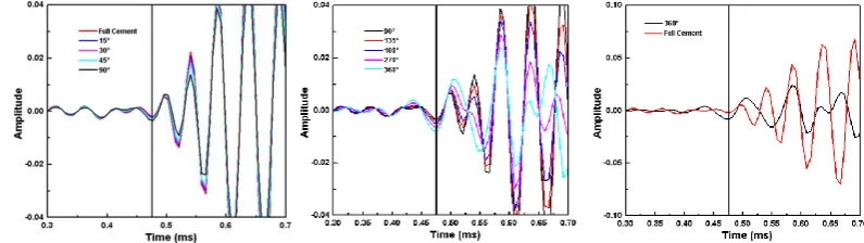
Figure 4. The sound field of different missing angle (P - wave velocity is 3000m/s,the fluid ring thickness is 10.0mm).
In the simulation of P - wave velocity is 3800m/s which is a fast formation. At this time, the characteristic wave first wave travelling time is about 0.475ms and the stratum wave first wave travelling time is about 0.525ms.The stratum wave travelling time is close to the characteristic wave, which interferes the characteristic wave. Next, we simulate the case that stratum wave velocity is 3000 m / s (medium velocity), and other parameters are consistent with the previous. The sound field of different missing angle is as shown in Figure 4. It is found from the figure that the first wave travelling time of the characteristic wave is 0.435 ms, and the first wave travelling time of the stratum wave is 0.585 ms. There is less interference between them. It is convenient to use characteristic waves to evaluate the II interface cementing quality.
Since mutual interference between the two is relatively small, it is convenient for evaluating the cementation condition of the II interface cement with the characteristic wave.
From the case of 360 ° missing and fully cemented. We can see that the first wave travelling time of stratum wave is 0.585ms, significantly bigger than first wave travelling time of the characteristic wave which is 0.435ms. In this case the interference is relatively small between the stratum wave and the characteristic wave. As a result, using characteristic wave evaluation II interface cement cementing situation is easier.
[image:4.595.101.494.376.489.2]the first wave amplitude of the characteristic wave increases. When the missing angle is less than 50°, there are some small mutations in the amplitude. If the missing thickness is greater than 5mm, the greater the thickness of the fluid ring, the greater the amplitude of the first wave would be. This is consistent with the conclusions obtained in the rapid stratum.
[image:5.595.157.440.418.539.2]Therefore, in the II interface part missing model of the vertical, it can be considered as that the characteristic wave amplitude changes with the missing angle equivalent to the channel fluid ring thickness.
Figure 5. Distribution of the characteristic wave first wave amplitude changes with the missing angle in different fluid ring thickness (Peak,P - wave velocity is 3000m/s).
Study on the Characteristic Wave of bow Missing in the Horizontal Well
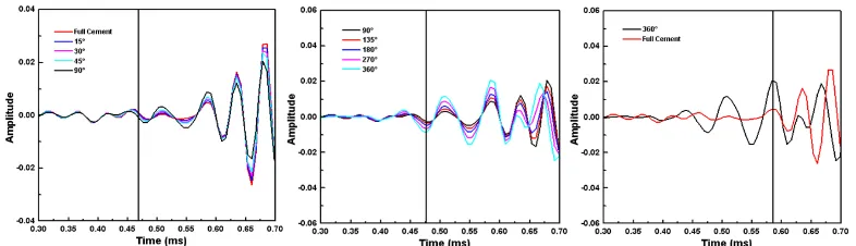
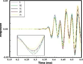
Vertical wells are prone to form II interface sector cement missing. Due to the gravity, bow missing may be formed in the upper layer of the horizontal well as shown in Figure 1(b). In order to study the effect of missing height on the sound field ,the nine cases with bow heights of 5mm, 10mm, 15mm, 20mm, 25mm, 30mm, 40mm, 50mm, and 60mm are simulated separately, and choose wave from spacing is 1.0m as shown in Figure 6.
(a) (b)
Figure6. (a) Comparison of sound field waveforms with different bow heights (b) Waveforms of different channeling types which is computed by real axis integration method.
Sound field first wave of different bow missing heights received from source distance is 1.0 m as shown in Figure 6(a). The travelling time of the four sets of first wave (ie solid line) with a missing height 5-25mm is later than the missing height 30mm or more (ie the dotted line). The first wave travelling time with a missing height 5-25mm is around 0.385ms. And the first wave travelling time with a missing height greater than 30 mm is around 0.225 ms. Waveforms of different channeling types is computed by real axis integration method as shown in Fig. 6(b). The first wave travelling time of the one interface channel is about 0.225ms, and the first wave travelling time of the empty casing is about 0.19ms. Both of them are closer to the travelling time of the casing wave. And the first wave of the II interface channel is about 0.415 ms. That is, the travelling time of the II interface characteristic waves.
portion is within 30 mm, there is an bow water layer in the II interface portion. The II interface is not well coupled, and it is possible to form a II interface characteristic wave. Similarly, when the height of the missing portion exceeds 30 mm, it is equivalent to forming an empty casing in the portion of the wellbore, and the first wave of the empty casing is an casing wave. In addition, in the bow missing model, only the part area produces the channel, and the other areas are cemented intact. Since the first wave of good cementation well is the stratum wave, its velocity is smaller than the casing wave and the characteristic wave. The first wave of the bow missing is the casing wave or characteristic wave. Finally, it can be considered that the first wave with a height of 30-60mm is a casing wave, the first wave with the missing height of 5-25mm is II interface characteristic wave.
[image:6.595.228.364.274.379.2]It can be judged as that the four sets of the first wave with the missing height at 5-25mm are II interface characteristic wave. The amplitude of the first wave changes with the bow missing height as shown in Figure 7. It proves that the amplitude of the first wave increases as the height of the missing increases. The characteristic wave amplitude changes with the missing angle is equivalent the channel fluid ring thickness.
Figure 7. The characteristic wave changes with the bow height.
Conclusion
Comparison of characteristic wave amplitudes shows that it changes with sector missing angle in vertical well or bow missing height in horizontal wells. Though the wellbore model is different, the missing shapes are different. Finally, the amplitude of the characteristic wave changes with the measure of the missing value. It is equivalent to the amplitude of the characteristic wave changes with the fluid ring thickness in the full missing vertical well. In conclusion, no matter it is the sector missing angle or the bow missing height, they can be converted into the fluid ring thickness. Thus, this research provide a basis for establishing the distribution law of the characteristic wave amplitude changes with the missing amount, and provide reference to complex wellbore sound field analysis.
Acknowledgement
This research is financially supported by the National Natural Science Foundation of China (Grant No. 61802274).
This research is financially supported by Natural Science Research Project of Jiangsu Province of China (Grant No. 18KJB510044).
References
[1] Weijun Lin, Chengyu Zhang, Hailan Zhang, Xiuming Wang, Acoustic field in a cased well with a sectorial crossing channel, Acta Acustica. Commun. 30(2005)10-14.
[3] Xiumei Zhang, Jianmeng Sun, Xuelian Chen, Numerical Simulation of the Logging Response of Segmented Bond Tool ( SBT),Well Logging Technology. Commun. 28(2004) 515-517.
[4] Ruolong Song, Jinxia Liu, Wei Han, Kexie Wang, Parallel Computation of Sound Field in Non - axisymmetric Casing Well with Sectoral Cement, China academic Journal Electronic Publishing House. pp. 399.
[5] Xiumei Zhang, Weijun Lin, Xiuming Wang, Effect of eccentralization on acoustic wave propagation in cased boreholes, Journal of Applied Acoustics. Commun. 33(2014)1-8.
[6] Leslie, H.D., Randall, C.J, Multipole sources in boreholes penetrating anisotropic formations: Numerical and experimental results, J. Acoust. Soc. Am. Commun. 91(1992) 12-27.
[7] Jun Ma, Kexie Wang, Gang Li, Numerical simulation method of three - dimensional SV - FD with anisotropic media surrounding the sound field in wellbore, The 18th Annual Meeting of the Chinese Society of Geophysics, Beihai China, 2002.
[8] Ruolong Song, Jinxia Liu and Guijin Yao, Parallel finite difference modelling of acoustic field in nonaxisymmetric cased hole, Chinese Journal of Geophysics. Commun. 53(2010) 2767-2775.
[9] Xuelian Chen, Xiaoming Tang and Conghui Zhang, Finite-difference numerical simulation and analysis on nonaxisymmetric acoustic field in cased borehole, Chinese Journal of Geophysics. Commun. 58(2015) 318-326.
[10] Ruijia Wang, Wenxiao Qiao, Numerical modeling of three-dimensional acoustic reflection logging while drilling, Chinese Journal of Geophysics. Commun. 58(2015) 2201-2209.