2018 2nd International Conference on Applied Mathematics, Modeling and Simulation (AMMS 2018) ISBN: 978-1-60595-580-3
Ray Tracing Dynamic Scenes Using Multiple Kd-trees
Jian ZHANG
*, Hui-long YU, Cui QIN, Jing ZHAO and Huan WEI
Nanjing Institute of Technology Nanjing, China
*Corresponding author
Keywords: Ray tracing, Dynamic scene, KD-tree, Render.
Abstract. With faster hardware and algorithmic improvements, real-time ray tracing is finally within reach. A variety of different data structures have been developed for ray tracing over the past decades. These spatial data structures crucial for fast ray tracing must be rebuilt or updated as the scene changes, and this can become a bottle-neck for the speed of ray tracing. In this paper, a novel algorithm is proposed to improve the rendering speed for static and moving objects by build kd-trees respectively, i.e., we construct multiple kd-trees. This building method allows for ray tracing animations without rebuilding the spatial index structures for the whole scene, just for dynamic objects. We implement the proposed algorithm for ray tracing dynamic scene on CPU+GPU platform, resulting in frame rates of 3~5 fps for 1024*1024 images, which improves rendering speed of dynamic scenes significantly.
Introduction
Ray tracing is a widely used and powerful rendering technique in computer graphics for generating photo-realistic images. The basic idea of ray tracing is an optic reversible method. To determine the color at each pixel of the image, one traces the path traversed by each ray of light arriving at the pixel back through several reflections and/or refractions. Ray tracing consists of three steps [1]:
1) generating primary rays;
2) traversing rays through a spatial index structure and rays intersection; 3) shading the corresponding intersection points.
It is a recursive process of computing mirror reflection and refraction. The deeper the recursive process continues, the more realistic of the image. After ray tracing, this can get the color at each pixel of the scene.
The most time-consuming phase of ray tracing is ray traversal [2], [3], i.e. step2, which requires a huge amount of ray-scene intersection tests. Generally, a variety of different data structures have been developed to accelerate the traversal step by reducing the intersection tests numbers. Although these acceleration structures exist (e.g., grids, kd-trees, octrees, and variant of BVHs), they fall into only two classes: spatial subdivision techniques, and object hierarchies. Spatial subdivision techniques uniquely represent each point in space, but each primitive can be referenced from multiple cells; object hierarchy techniques reference each primitive exactly once, but each 3D point can be overlapped by anywhere from zero to several leaf nodes (also see [4]). Grids, octrees, and kd-trees are examples of spatial subdivision, with varying degree of regularity (or “arity” of the subdivision [4]); bounding volume hierarchies and their variants (bounding interval hierarchies, s-kd trees, b-kd trees,) are object hierarchies.
Kd-trees are considered by many to be the best known method to accelerate ray tracing of static scenes [5], [6]. While kd-trees are well suited for static scenes, considerable effort is required for building them well. Though efficient algorithms with O (nlogn) complexity exist [7] they often require seconds to minutes even for moderately complex scenes. This pre-processing time is almost negligible for walk-through applications with a static geometry environment, however it is not acceptable to update or rebuild KD-trees at runtime due to changes in the scene.
1) Motion decomposition [8]. The motion decomposition approach requires that the connectivity of the deformable mesh is constant and that the motion is semi-hierarchical. In particular, Günther et al. assume that the motion is locally coherent. If this is the case they can decompose the motion into two parts: affine transformation and residual motion. Subtracting the affine transformation from the deformations yields a local coordinate system in which the (residual) motion of the vertices is typically much smaller. The residual motion of each triangle is bounded by a fuzzy box, a box bounding the motion of each vertex in the local coordinate system. Motion decomposition is only efficient when it operates on coherently moving primitives. The motion decomposition approach is restricted to semi-hierarchical, locally coherent motion handling random motion is not supported. Furthermore, the help of the application is needed to provide additional information such as bone and skinning information.
2) Multi-level kd-tree [9]. In this method, a bounding box is created for each object and a KD-tree is built for each bounding box. Therefore, it only needs to rebuild the top level of the kd-tree, not the whole kd-tree. The multi-level KD-tree is restricted to characteristics of the movement, and the range of application is narrow.
3) Rebuilding kd-tree each frame parallel [10-12]. Lots of researches focused on ray tracing dynamic scenes using fast KD-tree base on multi-core architectures to reduce the rebuilding time. These methods do not take into account the characteristics of different movements and the distribution of moving objects, resulting in long rendering time.
This paper studies the characteristics of dynamic scenes, proposes a new method of fast rendering for dynamic scenes. The objects in the scene are divided into two parts: static and dynamic, and the acceleration structures are built respectively. While rendering frames, update dynamic part of the acceleration structure, and remain static part of the same. While the detection light traversal, traversal the two acceleration structures.
Fast Rendering Algorithm for Dynamic Scenes
Dynamic scene rendering procedure includes the updating and traversal of the acceleration structure. According to the movement patterns of dynamic scenes and the distribution of moving objects, build kd-trees for static objects and moving objects respectively. Then only those kd-trees of moving object need to be updated during rendering process. Since a number of kd-trees are built, when traversal, each tree must be traversed, need to determine the correct light intersection point. The detail of the algorithm is described in this section. It is worth mentioning that, in order to improve the speed, the kd-trees’ build, update and traversal are implemented in the graphics processor unit (GPU) [13].
Fast Rebuild of KD-tree
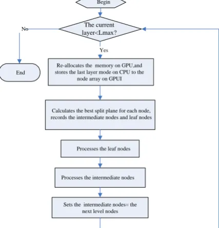
According to KD-tree creation method, it can be seen that there are so few upper nodes that the parallel processing is difficult. Therefore, it is unwise to implement the whole build KD-tree algorithm on GPU due to waste of CPU resources. So we divide KD-tree into upper and low levels, the upper tree level are built on CPU while the low tree level is built on GPU. The aim is to: 1) increase the parallel granularity of the low tree level on GPU; 2) at the same time of rendering the current image on GPU, building the KD-tree’s upper tree level of the next frame on CPU. CPU plus GPU in this way further improves the rendering speed.
When building kd-tree on CPU, the splitting plane is selected using SAH algorithm, from top to lower, stop building until the maximum level value (we choose the maximum level= 4). The related data of this maximum level node is transmitted to GPU to build the remaining levels of the KD-tree. The specific process is shown in Fig. 1.
level of intermediate node parallel processing, as shown in Fig. 2. The iteration process stops when reaching the threshold of the maximum number of layers.
When ray tracing a dynamic scene, only those kd-tree structures built for dynamic objects are need to rebuilt. The number of mesh which needs to be rebuilt is fraction of the total meshes in the scene. For example, the 110K triangles Kitchen with 7K animated triangles (from the BART of Stanford University), the acceleration structure is rebuilt quickly, as showed in Table 1.
Begin
Processes the leaf nodes
Processes the intermediate nodes Yes No
End
Re-allocates the memory on GPU,and stores the last layer mode on CPU to the
node array on GPUI
Calculates the best split plane for each node, records the intermediate nodes and leaf nodes
The current layer<Lmax?
[image:3.595.192.406.158.381.2]Sets the intermediate nodes= the next level nodes
Figure 1. The flow chart of KD-tree building on GPU.
4 3 2 4 3 2 1
move the intermediate nodes to the front of the array and the leaf nodes to the end
4 5 6 3
2
1 nodes which will be spilt in the next levelSet the intermediate nodes as the father The current layer nodes
Paralley compute the best split plane for each node,then split the father node
Intermediate node Intermediate node Leaf node Leaf node Intermediate node Intermediate node Intermediate node Intermediate node Intermediate node Intermediate node Intermediate node Intermediate node Intermediate node Intermediate node Leaf node Leaf node
[image:3.595.152.434.382.602.2]Figure 2. The schematic diagram of the node processing.
Table 1. The cost of updating and kd-tree rebuilding for the animated objects and the total scene.
The number of triangles
The cost of updating (ms)
The cost of kd-tree rebuilding(ms)
Animated objects 7K 112 31
Total scene 110K 112 434
The cost of updating is the time for calculating the new position of those animated triangles according to the motion track, therefore, it has nothing to do with the rebuilding cost.
Multiple KD-trees Traversal
these multiple intersection point should be recorded, the distance between the intersection point and the start point of the light should be determined. The true intersection point is the nearest.
[image:4.595.77.528.356.452.2]In the condition of the same total triangles, the cost for traversal one kd-tree is less than for multiple kd-trees. In the same condition (view angel and without rebuilding kd-tree), the time for traversal shows in Table 2.
Table 2. The cost of rebuilding kd-tree each frame and partially rebuilding.
rebuilding kd-tree per frame
partially rebuilding
with box without box
the cost of traversal(ms) 286 428 378
In Table 2, all results use the Kitchen scene at 10242 with 6 light sources and 4 reflection bounces.
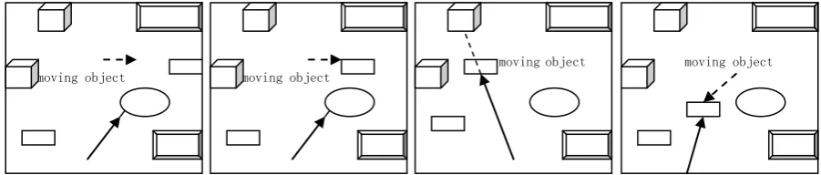
In the actual scenario, the moving objects are just a small part of the scene, and a large number of light may not intersect with the moving object, then the light traversing the dynamic objects becomes a waste. Considering the spatial relationship of the light and the objects in the scene, the light intersects with object including four situations: 1) the light only intersects with static objects; 2) the light intersects with both static and moving objects with the static objects blocked the dynamics objects; 3) the light intersects with both static and moving objects with the moving objects blocked the static objects; 4) the Light only intersects with moving objects. The four situations are shown in Fig.3.
Figure 3. Light intersects with objects in the scene.
For the first situation, it just needs to traverse the static KD-tree in rendering process. However the relative location of moving objects must be pre-calculated. For the second and the third, it need to traverse both static and dynamic KD-trees, and compare the distance of the two intersection point to the start point of the light, and choose the nearer as the intersection point for next step calculation. For the fourth, only need traversal dynamic KD-trees. In either case, it is necessary to determine the relative location of the moving objects/static objects and the light before the traversal.
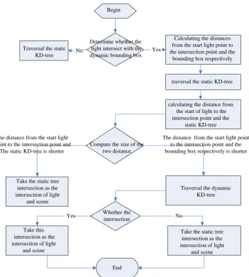
Firstly, it needs to determine whether the light intersect with the dynamic bounding box for every light. If “No”, then traversal the static KD-tree, set the light-box intersection point as the light-scene intersection point. If “Yes”, calculating the distances from the start light point to the intersection point and the bounding box respectively, then traversal the static KD-tree, calculating the distance from the start of light to the in the Specific processes shown in Fig. 4. The cost of traversal for partially rebuilding reduces to 378ms.
moving object moving object
Begin
Determine whether the light intersect with the dynamic bounding box
Calculating the distances from the start light point to the intersection point and the
bounding box respectively Traversal the static
KD-tree
Traversal the dynamic KD-tree
Whether the intersection
Take the static tree intersection as the intersection of light
and scene Take this
intersection as the intersection of light
and scene
End
Yes No
The distance from the start light point to the intersection point and the bounding box respectively is shorter The distance from the start light
Point to the intersection point and The static KD-tree is shorter
No Yes
traversal the static KD-tree
calculating the distance from the start of light to the intersection point and the
static KD-tree
Compare the size of the two distance
Take the static tree intersection as the intersection of light
[image:5.595.123.475.67.458.2]and scene
Figure 4. The flow chart of KD-tree traversal.
Algorithm Implementation
The specific process of the proposed multiple kd-tree rending algorithm is described as:
1) Store the initial image data of the dynamic scene, and divide it into static and dynamic parts;
2) Build dynamic kd-tree and static kd-tree according to the above data;
3) Rend the current image frame according to the kd-tree above constructed, and update the data structure of next image frame;
4) Go back to step 3).
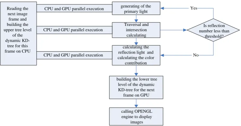
During the travesal process on GPU, partial data structure updating task can be implemented on CPU to further accelerate the rending speed. The whole framework of the proposed algorithm is shown in Fig. 5. To avoid the time consuming on the data switching between CPU and GPU, the KD-trees structure, the texture data, the starting point and the direction of the light are written into the texture memory on GPU. The specific process is as follows:
1) Generating of the primary light;
2) Intersection calculating of the light and objects in the scene, and determining the visibility of the light source;
3) Calculating the color contribution of intersection point to the image pixel;
4) Calculating the reflection light. If the terminal condition not met, then backing to 2);
5) while the above four steps processing on GPU, reading the next image frame and building the upper tree level of the dynamic KD-tree for this frame on CPU;
Traversal and intersection
calculating
Is reflection number less than
threshold? CPU and GPU parallel execution
CPU and GPU parallel execution
CPU and GPU parallel execution No Yes
building the lower tree level of the dynamic KD-tree for the next
frame on GPU
calling OPENGL engine to display
images Reading the
next image frame and building the upper tree level
of the dynamic
KD-tree for this frame on CPU
generating of the primary light
calculating the reflection light and calculating the color
[image:6.595.92.499.87.301.2]contribution
Figure 5. The flow chart of the dynamic scene rendering on CPU-GPU platform.
Results and Discussion
The described algorithm has been tested on an Intel CoreII 6320 CPU with an NVIDIA GeForce GTX 285 graphics card. The kitchen scene consists of 110K triangles, including one kitchen and one moving small car consisting of about 7K triangles.
[image:6.595.91.503.415.486.2]The rendering results are shown in Fig.6 with the test results are shown in Table 3.
Figure 6. The rendering result of the kitchen scene.
Table 3. Experimental results.
resolution
Primary(ms) (without shadowing)
Primary(ms) shadowing
3 bounce(ms) (with shadow)
1024×1024
the moving car in
the view 274 374 468
the moving car
out of the view 255 359 406
Static scene 47 93 203
512×512
the moving car in
the view 239 359 390
the moving car
out of the view 218 328 380
Static scene 16 31 62
[image:6.595.87.506.520.721.2]When there is no moving objects in the view, and only considering about the primary ray without shadowing, just one static kd-tree need to be traversed. So we only need to judge whether the primary ray intersecting with the boundary box of dynamic kd-tree. While considering about the shadowing and the reflected ray, the total rending cost is increased. On the one hand, while adding the shadowing judgement, the number of probe rays is increased and part of the probe rays may be intersect with the dynamic kd-tree. On the other hand, while adding reflecting rays, the reflecting rays may be intersect with the dynamic kd-tree.
When increasing the image resolution, the number of light is increasing. The difference with the static scene rendering, the rendering time of dynamic scenes does not increase in proportion to the resolution. The reason is because the reading of the dynamic data and acceleration structure updating have nothing to do with the rendering process during the dynamic scene rendering process.
Conclusion
In this paper a new method of fast rendering for dynamic scenes is proposed. The objects in the scene are divided into two parts: static and dynamic, and the acceleration structures are built respectively. While rendering frames, it only needs to rebuild or update the dynamic KD-tree while keep the static KD-tree stable. We implement this fast rendering for dynamic scene at 3~5 fps for 1024*1024 images on CPU+GPU platform.
Acknowledgement
This research was financially supported by the National Science Foundation. (Grant No. 61701220), Jiangsu Higher School Natural Science Research Project (Grant No. 17KJB510023) and Research fund of Nanjing institute of engineering (CKJB201406).
References
[1] Andrew S. Glassner. An introduction to ray tracing[M]. Academic Press Ltd. London, England. 1989.
[2] Bruce Walter, George Drettakis, Steven Parker. Interactive Rendering Using the Render Cache, Rendering Techniques '99, G. Larson,D. Lichinski (eds), Springer-Verlag (10th Eurographics workshop on Rendering, Granada, Spain).
[3] Bruce Walter, George Drettakis, Donald P. Greenberg. Enhancing and Optimizing the Render Cache, Rendering Techniques 2002 (13th Eurographics Workshop on Rendering, Pisa, Italy), Springer-Verlag, pp: 37-42,2002.
[4] Wald I., Havran V.: On building fast kd-trees for ray tracing, and on doing that in O(N log N). Tech. rep., SCI Institute, University of Utah, 2006.
[5] Lu H, Bao P, Feng J. OpenCL-based real-time KD-tree and ray tracing for dynamic scene[J]. Journal of Computer-Aided Design and Computer Graphics, 2013, 25(7):964-973.
[6] Hapala M,Havran V. Review:KD-Tree traversal algorithms for ray tracing[J].Computer Graphics Forum, 2011, (01):199-213.
[7] Niels Thrane and Lars Ole Simonsen. A comparison of acceleration structures for GPU assisted ray tracing. Master’s thesis, University of Aarhus, 2005
[8] J. Gunther, H. Friedrich, I. Wald, H.-P. Seidel, and P. Slusallek. Ray tracing animated scenes using motion decomposition. Computer Graphics Forum25, 3 (Sept. 2006), 517–525. (Proceedings of Eurographics).
[10] B.Choi, R.KomuraVelli,V Lu,,H.Sung,R.L.Bocchino,S.V AdVe,and J.C. Hart, Parallel SAH k-D Tree Construction in Proceedings of High Performance Graphics 2010, pp. 77-86.
[11] Xin Yang, Duan-qing Xu, Lei Zhao.Ray Tracing Dynamic Scenes using fast KD-tree Base on Multi-Core Architectures. 2008 International Conference on Computer Science and Software Engineering.2008.
[12] Budge B, Anderson J, Garth C. Joy K.A straightforward CUDA implementation for interactive raytracing.In RT, pp: 178-185.2008.
[13] Foley T, Sugerman J. KD-tree acceleration structures, for a GPU ray tracer[C]. SIGGRAPH /EUROGRAPHICS Workshop on Graphics Hardware: Proceedings of the ACM SIGGRAPH /EURO-GRAPHICS conference on Graphics hardware. New York: ACM Press, pp: 15-22. 2005.