http://dx.doi.org/10.4236/jcc.2015.35022
A Way to Set up Security Layer over Internet
Xiangyi Hu, Guifen Zhao, Guanning XuBeijing Key Laboratory of Network Cryptography Authentication, Beijing Municipal Institute of Science & Technology Information, Beijing, China
Email: [email protected] Received March 2015
Abstract
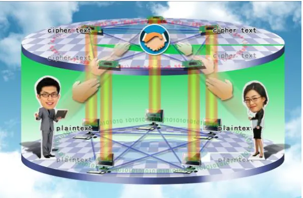
A security architecture using secret key algorithm and vertical authentication mode is proposed. Establish security protocols in the chip of smart key at network client or mobile phone, and estab-lish key exchange protocol in the chip of encryption cards at network key management center. A combined key real-time generation algorithm is used to solve the update and management prob-lems. Online or offline authentication and documents encryption transmission protocols are adopted to achieve credible connection between users. Accordingly, set up security layer over In-ternet, which provides convenient encryption ability to each network user, and build credible and secure network system.
Keywords
Security Layer, Vertical Authentication, Combined Secret Key, Credible Network, Online Authentication, Offline Authentication
1. Introduction
With the application and popularization of network, network has already widely applied to job, study, daily life, social communication and other fields. Network security always restricts rapid development of network applica-tion. It’s urgent to solve network security problems [1]-[6], especially the authentication and secure documents exchange problems for mass users. There are hidden troubles in IPv4 network communication protocol. There-fore, it is necessary to build security layer over Internet for users’ information security demand [7], especially to master fast key exchange technology. However, if use international third-party authentication security architec-ture, such as using public key algorithm RSA or ECC establish authentication and data encryption system on In-ternet, the cost is too high, which can not achieve the purpose to establish security layer over Internet.
2. Security Architecture of Vertical Authentication
2.1. Security Architecture at ClientThe proposed security architecture uses smart card at client by way of client encryption system hardware, in-cluding USB key or SD key devices.
Establish client encryption system in smart card chip and write secret key cipher algorithm, hash algorithm, combined secret key real-time generation algorithm, offline authentication, online authentication protocol, of-fline signature and encryption protocol, online signature and encryption protocol, and data including identifica-tion Bi of smart card, a three-dimensional matrix Ti of key seeds, and a three-dimensional matrix E of another set of key seeds, i = 1 - n, n is the total number of network users.
Each client smart card owns a unique identification Bi, and different from each other. Corresponding with smart card identification, the three-dimensional matrix Ti of key seeds is different from each other. The ele-ments of Ej stored in user’s smart card of the same friends group are the same. j = 1 - m, m < n.
2.2. Security Architecture at Server
Set up key exchange center on network which consists of servers and encryption cards. Regard encryption cards as encryption system hardware of key exchange center. Establish server encryption system in encryption card chip and write secret key cipher algorithm, hash algorithm, combined secret key real-time generation algorithm, a three-dimensional matrix D of key seeds, key exchange protocol, and store the cipher text of all users’ three-dimensional key seeds matrix Ti in user key data base. Each record in user key data base consists of iden-tification Bi of smart card, 32 × 2 matrix Gi composed with digest information of ideniden-tification Bi and random number Si, cipher text of three-dimensional key seeds matrix Ti, digital signature of three-dimensional key seeds matrix Ti. Specifically, generate storage key Ki according to matrix Gi and three-dimensional matrix D, and then using Ki perform encryption and signature respectively for identification Bi and elements of three-dimen- sional matrix Ti. i = 1 - n, n is the total number of network users.
3. Key Management for Secret Key Cryptography
A secret key management technique is proposed to perform key management achieve real-time generation and secure exchange.
3.1. Procedure Key
[image:2.595.166.464.510.704.2]Assume that procedure key is GK. GK is a set of random numbers, 128 bit, generated by random number gene rator of client smart card. Use procedure GK performs signature and encryption for sender user’s documents.
Moreover, use another user key YK encrypt the procedure key GK. The cipher text of GK is GK’. Send GK’ to key exchange center and decrypt it, and then use receiver user’s key encrypt the plaintext and get a new cipher text. Transmit the new cipher text to receiver. Consequently, two users realize secure exchange of procedure key GK via key management center. Specifically, the plaintext of GK doesn’t appear out of encryption card chip of key exchange center.
3.2. User Key
Assume that user key is YK. YK is generated by combined key real-time generation algorithm in client smart card. If users are under online environment, user key YK is used to encrypt the procedure key GK, which can achieve secure exchange of procedure key. If users are under offline environment, user key YK is used to per-form signature and encryption, and encrypt identifying code to generate signature code within offline authenti-cation protocol. User key adopts centralized generation, centralized writing, and centralized distribution with hardware equipments.
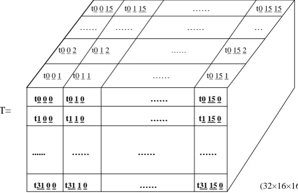
While initializing user key, random number generator of encryption card equipped in key exchange center generate a set of random numbers, and then regard these random numbers as key seeds and constitute a (32 × 16 × 16) three-dimensional matrix T. There are 8192 elements in matrix T. Each element is 0.5 byte. Totally the matrix occupies about 4 KB. That is the elements of matrix T are 4 bit character string. Write the elements of matrix T into client smart card, and distribute user key with smart card hardware equipments.
Assume that three-dimensional key seeds matrix T is shown in Figure 2.
While running client authentication protocol or signature protocol, encryption protocol in user’s smart card, client encryption system generates a set of user key YK according to combined key real-time generation algo-rithm on the basis of (32 × 2) matrix G and three-dimensional key seeds matrix T, or generates a set of user key YK on the basis of (32 × 2) matrix G and three-dimensional key seeds matrix E.
Because different users own different elements of three-dimensional matrix Ti, users can perform offline au-thentication. Different users own the same three-dimensional matrix E. Users can perform documents encryption transmission.
[image:3.595.164.459.512.703.2]Random number generator in encryption card quipped at key exchange center generates a set of random numbers, constitutes the elements of (32 × 16 × 16) three-dimensional matrix Ej and distributes to all corres-ponding users within the same friends group. The distribution procedure of Ej is described: one user among a user group login key exchange center after authentication, and submit other users’ identification in the same friends group to key exchange center. The encryption system of key exchange center encrypt the elements of Ej using different key generated on the basis of corresponding identification Ti in encryption cards. Obtain cipher text of different Ej elements and transfer individually to corresponding client. At each client, encryption system decrypts the cipher text using key generated on the basis of Ti, and writes the plaintext of Ej elements into smart
Figure 2. Three-dimensional key seeds matrix T.
T=
(32×16×16)
t0 0 15 t0 1 15 …… t0 15 15
t0 0 1 t0 1 1 …… t0 15 1 1
t0 0 2 t0 1 2 …… t0 15 2 …… …… …… …
t0 0 0 t0 1 0 …… t0 15 0
t1 0 0 t1 1 0 …… t1 15 0
card. j = 1 - m, m < n.
3.3. Storage Key
Assume that storage key is K. K is used to encrypt all users’ elements of three-dimensional key seeds matrix T in the encryption cards chip at key exchange center. While key initializing, random number generator in encryp-tion card quipped at key exchange center generates a set of random numbers which are key seeds of key ex-change center and constitute the elements of (32 × 16 × 16) three-dimensional matrix D. There are 8192 ele-ments in matrix D, and each element is 0.5 byte, totally 4 KB. That is the eleele-ments of matrix D are 4 bit charac-ter string. Matrix D is similar with T, but the elements are different.
Write the elements of matrix D into encryption cards of key exchange center. Encryption system of key ex-change center generates a set of storage key K according to combined key real-time generation algorithm on the basis of (32 × 2) matrix GG and three-dimensional key seeds matrix D.
Assume that storage key is K1, K2,…, Kn. Storage key K1, K2,…, Kn encrypt the elements of three-dimen- sional matrix Ti separately in the encryption cards chip at key exchange center. After encryption, record the ci-pher text of Ti, corresponding user identification Bi and matrix GGi in user key data base at key exchange cen-ter.
Generate storage key Ki on the basis of (32 × 2) matrix GGi and (32 × 16 × 16) three-dimensional matrix D. i = 1 - n, n is the total number of network users.
When cipher text of three-dimensional keys seeds matrix Ti is called at key exchange center, firstly, the ci-pher text is decrypted in encryption card, and all users’ plaintext of three-dimensional key seeds matrix Ti doesn’t appear out of encryption card chip. Therefore, guarantee storage and running security of all users’ key seeds elements of three-dimensional matrix Ti at key exchange center. i = 1 ~ n, n is the total number of network users.
3.4. Combined Key Real-Time Generation Algorithm
Combined key real-time generation algorithm means that client smart card identity and the 256 bit hash value of a set of random numbers constitute a (32 × 2) matrix, for example matrix G or matrix GG. If the matrix is G, perform mapping for three-dimensional key seeds matrix T according to elements of (32 × 2) matrix G. The se-lected elements of three-dimensional matrix T constitute a user key YK. Similarly, storage key K is generated according to matrix GG and three-dimensional matrix D.
Generate a set of random numbers by random number generator of client smart card. Encryption system client calls hash algorithm to deal with the smart card identification Bi and the random numbers, and then obtains a set of hash value. The hash value constitutes a (32 × 2) matrix G. According to combined key real-time generation algorithm, constitute a user key on the basis of (32 × 2) matrix G and (32 × 16 × 16) three-dimensional key seeds matrix T.
Generate a set of random numbers by random number generator of encryption card at key exchange center. Encryption system at key exchange center calls hash algorithm to deal with the smart card identification Bi and the random numbers, and then obtains a set of hash value. The hash value constitutes a (32 × 2) matrix GG. Ac-cording to combined key real-time generation algorithm, constitute a storage key on the basis of (32 × 2) matrix GG and (32 × 16 × 16) three-dimensional key seeds matrix D. Storage key is applied to encrypt the smart card identification Bi and corresponding (32 × 16 × 16) three-dimensional key seeds matrix T.
Specifically, combined key real-time generation algorithm is that calls hash algorithm, for example SHA-1, SM3, etc. to deal with the smart card identification Bi and random numbers Si, and then obtains a set of 256 bit hash value. Divide the 256 bit hash value into 64 groups and each group is 4 bit, consequently, constitute a (32 × 2) matrix. Assume that (32 × 2) matrix comprised with 256 bit hash value of a set of random numbers is G.
( )
00 01 10 11
31 0 311 32 2
g g
g g
G
g g
×
=
(1)
The total number of matrix G elements is 0 - 15.
T. The first row and second column element of matrix G is g0 1, mapping the first row, g0 0 column and g0 1 page element of T. The element is selected and assumed it is kk1.
Similarly, the second row and first column element of matrix G is g1 0, mapping the second row and g1 0 col-umn elements of T. The second row and second colcol-umn element of matrix G is g1 1, mapping the second row, g1
0 column and g1 1 page element of T. The element is selected and assumed it is kk2.
Until the thirty-second row, g310 column and g311 page element of T is selected and assumed it is kk32. The kk1, kk2,..., kk32 compose a set of key which is user key or storage key.
3.5. Procedure Key GK, User Key YK and Storage Key K
Procedure key GK, user key YK and storage key K are all 128 bit. Repetition probability of GK is 1/2128. Basi-cally, GK is one-time.
User key and storage key are generated by combined key real-time generation algorithm. That is mapping three-dimensional matrix T according to 64 elements of (32 × 2) matrix G. The selected elements of three–di- mensional matrix T constitute a user key YK. There are 32 rows and 2 columns in matrix G, and each element is a number between 0 - 15, totally 16 varieties, therefore, there are 2 elements and 16 × 16 = 28 varieties in each row. For total 32 rows, the key variation is 2(8×32) = 2256. Accordingly, the key generated by combined key real-time generation algorithm, including user key and storage key, is basically one-time and not repeated.
4. Offline Security Protocol
While performing offline authentication between user 1 and user 2, both clients call the same three-dimensional key seeds matrix E stored in smart card to generate user key. Key exchange center is not needed while user key exchanging.
4.1. Offline Authentication Protocol
Firstly, client encryption system of user 1 generates a set of random numbers S in smart card. The hash value of identification B1 and random number S is identifying code L1, and constitutes matrix GG. User key YK1 is created according to matrix GG and three-dimensional matrix E, and applied to encrypt identifying code L1. The cipher text of L1 is signature code L1’. Client encryption system of user 1 sends the identification B1, identify-ing code L1 and signature code L1’ to user 2. The client encryption system of user 2 generates symmetric key YK2 according to matrix GG and three-dimensional matrix E in smart card, and decrypts signature code L1’ to obtain identifying code L2. Compare identifying code L1 and L2 for identification. If L1 ≠ L2, user 1 is illegal user, otherwise L1 = L2, user’s identity is true. Similarly verify the identification of user 2 according to the same protocol. Thereby, offline authentication between user 1 and user 2 is achieved [8].
4.2. Offline Signature and Encryption Protocol
Firstly, client encryption system of user 1 generates a set of random numbers S in smart card. The hash value of identification B1 and random number S is identifying code L1, and constitutes matrix GG. User key YK1 is created according to matrix GG and three-dimensional matrix E, and applied to encrypt document 1 and its digi-tal digest M1, and then get the cipher text and digidigi-tal signature of document 1. Client encryption system of user 1 sends the identification B1, matrix GG, the cipher text, digital digest, and digital signature of document 1 to user 2.
The client encryption system of user 2 generates symmetric key YK2 according to matrix GG and three-di- mensional matrix E in smart card, and decrypts the cipher text and digital signature of document 1 to obtain the plaintext and digital digest M2 of document 1. Compare digital digest M1 and M2 and validate integrity and credible. If M1 ≠ M2, document 1 has been tampered, otherwise M1 = M2, document 1 is integrate and credible. Thereby, offline cipher text transmission and integrity verification of document 1 between user 1 and user 2 is achieved.
5. Online Security Protocol
key seeds matrix T1 and T2 stored in respective smart card to generate user key. Key exchange center is needed while user key exchanging.
5.1. Online Authentication Protocol
Firstly, client encryption system of user 1 generates a set of random numbers S1 and S2 in smart card. S2 is the procedure key GK1. The hash value of identification B1 and random number S1 is identifying code L1, and constitutes matrix G. User key YK1 is created according to matrix G and three-dimensional matrix T1, and ap-plied to encrypt GK1. The cipher text of GK1 is GK1’. The GK1 is apap-plied to encrypt identifying code L1. The cipher text of L1 is signature code L1’. Client encryption system of user 1 sends the identification B1, identifi-cation B2, identifying code L1, signature code L1’ and GK1’ to key exchange center.
The encryption system at key exchange center generates storage key K1 according to identification B1 to de-crypt the cipher text of T1 and perform integrity verification. Generate user key YK-1 according to matrix G and T1 to decrypt the cipher text GK1’. And then generate storage key K2 according to identification B2 to decrypt the cipher text of T2 and perform integrity verification. The hash value of identification B2 and random number S1 is identifying code LL, and constitutes matrix GL. User key YK2 is created according to matrix GL and three-dimensional matrix T2, and applied to encrypt GK1. Encryption system of key exchange center sends the identification B1, identification B2, matrix GL, identifying code L1, signature code L1’ and cipher text of GK1 to user 2.
The client encryption system of user 2 generates symmetric key YK-2 according to matrix GL and three-di- mensional matrix T2 in smart card, and decrypts signature code L1’ to obtain identifying code L2. Compare identifying code L1 and L2 for identification. If L1 ≠ L2, user 1 is illegal user, otherwise L1 = L2, user is true user. Similarly verify the identification of user 2 according to the same protocol. Thereby, online authentication between user 1 and user 2 is achieved.
5.2. Online Signature and Encryption Protocol
Firstly, client encryption system of user 1 generates a set of random numbers S1 and S2 in smart card. S2 is the procedure key GK1. The hash value of identification B1 and random number S1 is identifying code L1, and constitutes matrix G. User key YK1 is created according to matrix G and three-dimensional matrix T1, and ap-plied to encrypt GK1. The cipher text of GK1 is GK1’. The GK1 is apap-plied to encrypt document 1 and the digi-tal digest M1 of document 1, and then obtain the cipher text and digidigi-tal signature of document 1. Client encryp-tion system of user 1 sends the identificaencryp-tion B1, identificaencryp-tion B2, matrix G, cipher text and digital signature of document 1, and GK1’ to key exchange center.
The encryption system at key exchange center generates storage key K1 according to identification B1 to de-crypt the cipher text of T1 and perform integrity verification. Generate user key YK-1 according to matrix G and T1 to decrypt the cipher text GK1’. And then generate storage key K2 according to identification B2 to decrypt the cipher text of T2 and perform integrity verification. The hash value of identification B2 and random number S1 is identifying code LL, and constitutes matrix GL. User key YK2 is created according to matrix GL and three-dimensional matrix T2, and applied to encrypt GK1. Encryption system of key exchange center sends the identification B1, identification B2, matrix GL, the cipher text and digital signature of document 1, and cipher text of GK1 to user 2.
The client encryption system of user 2 generates symmetric key YK-2 according to matrix GL and three-di-- mensional matrix T2 in smart card, and decrypts the cipher text and digital signature of document 1 to obtain the plaintext and digital digest M2 of document 1. Compare digital digest M1 and M2 in smart card of user 2 client. If M1 ≠ M2, document 1 has been tampered, otherwise M1 = M2, document 1 is integrate and credible. Thereby, online cipher text transmission and integrity verification of document 1 between user 1 and user 2 is achieved.
6. Advantages of Vertical Authentication
6.1. Characteristics of PKI The random number generated by PKI is the session key K.
Use AES (or 3DES) and K to encrypt data and obtain cipher text.
Use RSA (or ECC) and user’s private key to perform digital signature.
Use RSA (or ECC) and the public key of CA to encrypt the session key K.
6.2. Characteristics of Vertical Authentication Architecture
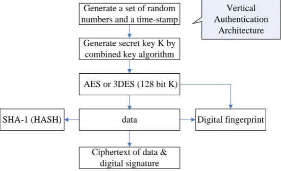
The characteristic of signature and encryption protocol used in vertical authentication architecture is that only one symmetric cipher algorithm is adopted to establish signature and encryption protocol, shown in Figure 4. The security architecture is simple, only a set of key is used while performing data encryption and signature.
Generate secret key K according to the combined secret key algorithm, and then exchange the K via random numbers and time-stamp.
Use AES (or 3DES) and K to perform digital signature and encrypt data to obtain cipher text.
6.3. Comparison between PKI and Vertical Authentication Architecture
[image:7.595.173.451.341.492.2]Compare the signature and encryption protocol of PKI third-party authentication and vertical authentication ar-chitecture. It is obvious that PKI calls 2 more asymmetric cryptography algorithms and 2 public key. Use public key algorithm performs twice encryption, one is encryption of digital digest and another is encryption of proce-dure key for key exchange. The vertical authentication architecture doesn’t call 2 asymmetric cryptography al-gorithms and 2 public key. Symmetric cryptography algorithm runs 100 times in computer and 1000 times in
Figure 3. Flow Chart of PKI signature and encryption protocol.
Figure 4. Flow chart of signature and encryption protocol used in vertical authentication architecture.
RSA (1024) public key of CA
RSA (1024) User’s private key
AES or 3DES (128 bit K)
Digital fingerprint ciphertext
SHA-1 (HASH) Ciphertext of data &
ciphertext of procedure key & digital signature
data
PKI
Generate a set of random numbers as
procedure key K
Generate secret key K by combined key algorithm
AES or 3DES (128 bit K)
SHA-1 (HASH)
Ciphertext of data & digital signature
data
Vertical Authentication
Architecture Generate a set of random
numbers and a time-stamp
[image:7.595.175.451.523.691.2]chipsets faster than asymmetric cryptography algorithm. That is why this method runs faster and high-efficiency than PKI.
7. Conclusion
The vertical authentication architecture is proposed using centralized key generation, initialization and distribu-tion via hardware equipments. Combined key real-time generadistribu-tion algorithm is applied to solve the problems of update and management. Online and offline authentication protocol can achieve credible connection between users and realize real name net play. Set up security layer over Internet, which provides convenient encryption ability for personal computer, mobile phone and other communication equipments of each network user, and achieve encryption transmission between users. The method can avoid APT attack and guarantee domestic net-work system secure and credible.
Acknowledgements
The work is supported by Innovation Project II-2: Research and Development of Cryptographic Authentication System in Cloud Computing Security (No. PXM2014_178214_000011), Beijing Key Laboratory of Network Cryptography Authentication, Beijing Municipal Institute of Science & Technology Information.
References
[1] Bai, J. and Jing, J.W. (2012) Look upon the Cryptography Challenge in Cloud. China Information Security, 11, 15-16, 26.
[2] Shen, C.X. (2012) Cloud Computing Security and Classified Security Protection. China Information Security, 1, 16-17. [3] Han, S. (2012) Key Technologies on Cloud Computing Data Security. University of Electronic Science and
Technolo-gy of China.
[4] Feng, D.G. (2011) Enter Cloud Computing Security Age. Netinfo Security, 3, 1-2.
[5] Zhang, W.-K. and Liu, G.-F. (2012) Data Security and Privacy Protection of Cloud Computting. China Information Security, 11, 38-40.
[6] Zhang, Y.Y., Chen, Q.J., Pan, S.B. and Wei, J.W. (2010) Key Security Technologies on Cloud Computing. Telecom-munications Science, 26, 64-69.
[7] Online Privacy Breakthrough as British Researchers Claim to Have Developed Way to Give the Internet a “Security Layer”.
http://www.dailymail.co.uk/sciencetech/article-2885677/Online-privacy-breakthrough-British-researchers-claim-devel oped-way-internet-security-layer.html?ITO=1490&ns_mchannel=rss&ns_campaign=1490