4192
SIMULTANEOUS COORDINATED TUNINGOF CES AND
PSS FOR SINGLE-MACHINE USING GENETIC ALGORITHM
1ENDRO WAHJONO, 2ONYASRARULQUDSI, 3DIAH SEPTI YANARATRI
Industrial Electrical Engineering Study Program, Department of Electrical Engineering Electronic Engineering Polytechnic Institute of Surabaya, Indonesia
E-mail: 1[email protected], 2[email protected], 3[email protected]
ABSTRACT
This paper presents a new coordinated design between Power System Stabilizer (PSS) and Capacitive Energy Storage (CES) using Genetic Algorithm (GA). A GA will determines optimal parameters for PSS and CES by tuning parameters PSS and CES simultaneously. The optimization results can change the value of PSS and CES parameters which can also cause oscillation on the system. This problem is formulated as an objective function with limits consisting of damping ratio and damping factor. The approach is succesfully tested on single-machines generator models. The optimization results show that this method is effective enough to damp the oscillation, so as to give an idea of the dynamic stability of the single-machine system.
Keywords:CES, PSS, Single-Machine, Genetic Algorithms
1. INTRODUCTION
The power system stability has been considered as an important issue to protect power system operation.The pattern of load changes that occur so fast in aninterconnected system causes oscillations on each machine that connected to the system. These oscillations affect each other, so theinterconnected machineis interacted to reduce these oscillations in order to reach the stable condition [1][26].
The large oscillations cause system instability. This condition does not guarantee that the system will return to the steady-state condition. So many researchers developed various types of controllers to dampen these oscillations so the system back in a steady-state condition with a relatively short time after the fault [2] - [7]. This stability analysis focuses on dynamic stability caused by small disturbances, such as changesof theload when peak load condition.
CES (Capacitive Energy Storage) is a device for large power storage and release simultaneously.CES consists of the capacitor storage and Power Conversion System (PCS) with integratedcontrol and protection functions.The normal operating point of the capacitor can be arranged so that the maximum energy absorption equals to the maximum energy discharge. This condition makes CES is very effective in reducing oscillations caused by load changes [8-11], [23-24].
The PSS (Power System Stabilizer) installationas thecontroller has been shown in reference [3] intended to improve the controller performance in reducing oscillations.In its operation, the controller is working together with AVR (Automatic Voltage Regulator). These controllers are effectively used to dampen electromechanical oscillations. Therefore, this paper proposes the use of CES and PSS as an alternative method for reducing the system oscillation [12], [16-18], [20-22].
Generally, tuning parameters of PSS and CES are multimodal optimization problems. Therefore, most algorithms fail to get a fairly accurate solution, especially on large systems. Additionally, the optimization parameter limits make it harder to find the optimal solution. To solve all the above problems, this paper proposed.Genetic Algorithm (GA) to obtain optimal parameters that used as constants in the optimal coordination of CES and PSS operations simultaneously.
ISSN: www.jatit.org E-ISSN:
4193 calleda generation. Development of solutions is simulated by fitness functions and genetic operators such as reproduction, mutation, and crossover.
In this paper, GA is presented for optimizing the use of PSS and CES in a single-machine infinite bus (SMIB) synchronous generator. The PSS and CES parameters are effectively tuned with GA to obtain sufficient damping for oscillations due to load changes. The attenuation to the oscillations occurring is used as an objective function. Then the attenuation is converted to a fitness function using the Integral Time Absolute Error (ITAE) method. ITAE optimizes the absolute error and completion time not achieved by other methods [27]. Then the fitness value that has been obtained will be evaluated to get the optimal oscillation damping value. Thus, system security can avoid unwanted incidents.
2. SYNCRONOUS GENERATOR MODEL
Single-machine generator model in this paper is shown in figure 1 [13]. This generator model is a synchronous generator modeling in detail, including its control components.Generally, there are two main controls on this generator modeling, Load Frequency Control (LFC) and Automatic Voltage Regulator (AVR). Both controllers maintain frequencies and voltages in stable conditions in accordance with their limitations when there is a load changing on the system. The active power change affects the rotor angle δ which will directly affect the frequency. While the change of reactive power will affect the voltage magnitude. The excitation system will keep the voltage stable, but it does not affect the LFC. LFC will work independently to maintain frequency stability due to active power change.
∆
= ∆ −
(1)
With speed expressed in per unit, without explicit per unit notation,
∆ = (∆ − ∆ ) (2)
Laplace Transform of equation (xxx) is
∆ ( ) = [∆ ( ) − ∆ ( )] (3)
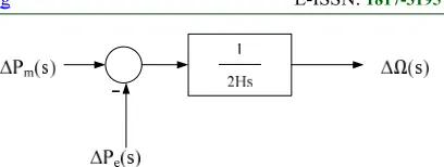
By deriving the swing equation of the synchronous generator in equation (1) - (3) there is a corelation between the mechanical power of the generator Pm and the electrical power of the load
[image:2.612.318.522.79.156.2]Pe as shown figure (1).
Figure 1. Mechanical power and the electrical power block diagram
2.1 LFC Model
LFC will keep the frequency stable at its limit. The frequency change will be known through the rotor angle change then the rotor angle error will be corrected. The error signal will be amplified and converted to active power. Then prime-mover will compensate for the change of active power. Figure (2) shows the LFC block diagram in the synchrous generator.
Figure 2. LFC block diagram
How sensitive the LFC to frequency changes depends on the frequency-sensitive load change DΔω, where D is the percent change of load divided by the percent change in frequency.
∆ ( )
∆ ( )
=
( )( )
( ) ( ) (4)
Change of -PL (s) as input and frequency deviation ΔΩ (s) as the output of blog diagram of LFC in figure (4). Close-loop transfer function between load changes -PL (s) and changes in frequency deviation ΔΩ (s) as equation (4).
2.2 AVR Model
[image:2.612.315.516.331.386.2]4194 diagram.
Vreff(s) KA
1+TAs
Ve(s) VR(s) VF(s) Vt(s)
VS(s)
- KE
1+TEs
KG
1+TGs
KR
1+TRs
Amplifier Exciter Generator
[image:3.612.312.522.93.210.2]Sensor
Figure 3. AVR block diagram
The addition of reactive power on the load will cause the voltage drop at the generator terminal. The voltage magnitude will be censored by the potential transformer (PT), then will be rectified to DC voltage by the rectifier. The DC signal will be compared with the set point so that the error signal will be compensated by the exciter so that the current on the generator field coil increases. The field current will amplify the emf on the generator so that the reactive power increases and the voltage return to the desired value.
( ) ( )=
( )
( )( )( )( ) (5)
Closed Loop transfer function between the terminal voltage generator Vt (s) to the reference voltage Vreff (s) is represented by equation (5).
3. CES (Capacitive Energy Storage)
CES consists of the capacitor storage and Power Conversion System (PCS) with control and integrated protection functions. Figure 4 shows the basic configuration of CES in electric power systems.Capacitor storage C consists of several discrete capacitors thatconnected in parallel. Resistance R connected in parallel to the capacitorC
is leaking and dielectric losses of the capacitor bank at CES.Storage capacitor connected to the grid through the Power Conversion System (PCS), which consists of ac to dc rectifier and dc to ACinverter. Two sets of six-pulse bridge converter are used to reduce harmonics that occurred.The function of bypass thyristoris to provide a pathway for currents Id when converter failure occurs. DC breaker allows the currents Id to flow through resistor RD, theenergydisposal if the converter fails.Neglecting the losses, bridge voltage Ed is as equation (7).
[image:3.612.315.506.377.425.2]= 2 cos − 2 (7)
Figure 4. CES configuration
By changing the phase angle α with a range value from 0° to 180°the capacitor voltage Ed able to be varied from a maximum positive value until the maximum negative value [10].This conditions will make CES is very effective in reducing oscillations caused by load changes because the normal operating point of the capacitor can be arranged so that the maximum energy absorption equals the maximum energy discharge.If Ed0 shows the initial voltage value, Edmax and Edmin shows the minimum and maximum voltage limits, then:
− = − (6)
=[ ] (7)
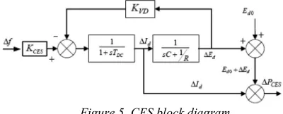
CES voltage must be returned to the initial value quickly, so after a fault occurs CES ready to work for the next fault. Therefore, the capacitor voltage deviation is used as a negative feedback signal in the CES loop control so so voltage recovery is achieved quickly as shown in figure 5 below.
Figure 5. CES block diagram
KCES is strengthening CES components can be arranged based on feedback Δf. WhereΔf is the change in the frequency of each area of the power system. So that the current changes ΔId is,
∆ =[ .∆ .∆ ] (8)
[image:3.612.313.513.523.604.2]ISSN: www.jatit.org E-ISSN:
4195
∆ = ∆ (9)
CES output power that released to the system during load changes are as follows:
∆ = ( + ∆ ). ∆ (10)
4. PSS (Power System Stabilizer) Models
[image:4.612.101.293.334.382.2]PSS (Power System Stabilizer) operates in the generator excitation system by adding a control signal on the AVR (Automatic Voltage Regulator) to dampentheoscillations of rotorgenerator.The angular speed of the generator is generally used as an input signal from this device [3], [5]. Figure 6 shows a PSS modelling.
Figure 6. PSS block diagram
KPSS is a gain component of the PSS that its value can be set. In lead-lag component, the phase can be adjusted by changing the value of T according to the needed phase values. TA and TB are √ ⁄ and
1 √⁄ .
While the washout components prevent offset voltage on a steady state.With this transfer function on equation (11), PSS can be used to generate a positive damping torque which the magnitude and phasecan be regulated.
=
(( √ )√ )
(11)
This controller was effective, economical, and secure in the power system to dampen oscillations. However, this controller is not effectively used for large electric power systems that interconnected with the generator layout that far apart. Therefore, the oscillation interaera usually occurs in such a system [5].
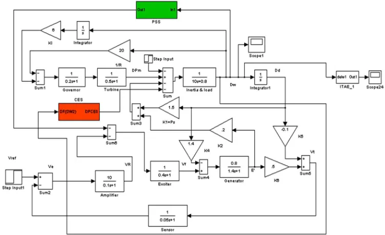
2.3 CES and PSS Coordination
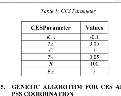
CES and PSScoordination in the system shown in Figure 7.CES dampen oscillations by detecting the frequency of feedback and then provide damping in the form of power CES (PCES). While PSS dampen oscillations by detecting the frequency of feedback and then provide damping through the excitation system. Figure 7 shows the modeling of the generator by the addition of CES and PSS. In Table 1, have also shown some initial parameters of CES.
s Ts T
w w 1
Saturasi
max S
V
min S
V s
Ts T
B A 1 1
s Ts T
D C 1
1 Vs
PSS
K
[image:4.612.127.503.480.710.2]Gain Blok Washout Blok lead-lag
4196
Table 1: CES Parameter
CESParameter Values
KVD -0.1
Tdc 0.05
C 1
Tdc 0.05
R 100
Ed0 2
5. GENETIC ALGORITHM FOR CES AND
PSS COORDINATION
Nonlinearity and discontinuity system caused some optimization problems cannot be solved analytically.The appropriate method to solve these issues is the direct search method. The direct search method using a variety of ways to find appropriate solutions, such as random searches, or searches that inspired by the biological sciences such as genetic algorithms [14].
There are many variations in genetic algorithms, but specifically in this research proposed a genetic algorithm for optimization of CES and PSS in single-machine. A genetic algorithm is a search algorithm based on the mechanism of natural selection and natural genetics. In this research, there are six variables (KPSS, Tw, TA, TB, TC, TD) which are encoded intoPSS chromosomes and six variable (KCES, KVD, TDC, C, Ed0, R) encoded into CES chromosomes.Each chromosome contains a gene that encodes the information stored in the chromosomes. To resolve the above problems is used real number encoding by thevalue genes are in the interval of numbers between 0 and 1.
After the encoding scheme is determined, a genetic algorithm is initialized to a population by the N number of chromosomes. The gene that fills each chromosome randomly generated using a uniform distribution. Each chromosome will be encoded into a specific individual with the highest fitness. A new population is generated by using the mechanism of natural selection, selecting individuals in proportion to the value of fitness, and natural genetics are crossover and mutation. The steps genetic algorithm can be written as the figure 8.
For real number encoding, a gene 'g' is used to represent a real number between 0 and 1. By using a certain interval, the lower limit rb and the upper limit ra can be performed in the following formula:
= + ( − ) (12)
An individual is evaluated by a certain function as a measure of its performance. In nature evolution, individuals who have higher fitness will be alive while individuals that have low fitness will die.In this study, a solution searched to minimize the function h (minimization problem) so that the function hcannot be used directly.This is due to the rule that individuals with higher fitness values can survive in the next generation. Therefore the value of fitness that can be used according tothe equation:
= (13)
that means that the smaller the value 'h', the greater the value 'f'. To avoid the value 'f' infinite due to the value of 'h' is equal to zero, should be added a number which is considered very small so the fitness value becomes:
= (14)
The h function is a damping function obtained using the ITAE method. In this paper, the objective function (ITAE) is obtained using the equation (15).
ℎ = | ( )| (15)
After obtaining the value of fitness then will be ranked according to thefollowing equation:
( ) = − ( − ) ( ) (16)
where R (i) declare the i-th individual rank.The selection of two pieces of chromosomes as parents, which will be acrossovered, carried out proportionally based on the fitness value. The selection method that used in this research is the roulette wheel method. A chromosome with greater fitness value will substituteanother chromosome with lower fitness value. Crossover is done to avoid the early convergences. Each chromosome will choose its partner to do crossover randomly. The frequency of the crossover operator controlled by the value of Pc. In any population, as many as pc x the population_size, do the crossover. The higher the value of the crossover probability, then the sooner a new structure introduced in the population. In this research, crossover probability Pc used is 0.8.
ISSN: www.jatit.org E-ISSN:
[image:6.612.97.523.67.460.2]
4197
Figure 8. Genetic Algorithm for CES and PSS Coordination.
6. RESULTS AND DISCUSSION
[image:6.612.104.318.69.452.2]Simulations were conducted to prove the suitability of the method. Table 2 is a parameter of the GA as a method to obtain optimal values of CES and PSS constants. Value optimization of system performance in each generation in the convergence-plot on a graph shown in Figure 5.
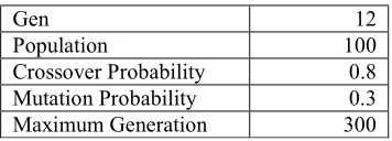
Table 2. Parameter DE
Gen 12
Population 100
[image:6.612.331.523.354.451.2]Crossover Probability 0.8 Mutation Probability 0.3 Maximum Generation 300 Optimization value of the system performance on each iteration convergence-plot on a graph shown in Figure 7.
Figure 9. GA Convergence Graph
[image:6.612.317.524.603.719.2]For the coordination of CES and PSS parameters using genetic algorithms, can be seen in the table below.
Table 3. Parameters of CES and PSS Coordination Using Genetic Algorithm
No. CES Parameter PSSParameter 1 KCES 0.8413 KPSS 3
2 C 0.1197 Tw 0.6559
3 R 0.8367 TA 0.9231
4 Edo 5 TB 0.0416
5 Kvd 0.9111 TC 0.9231
6 Tdc 0.0825 TD 0.0416
These parameters will be used as control constants in CES and PSS operations. Thus, the performance of CES and PSS becomes optimum.
a. Frequency Changes Response
CES and PSS simulation application in a single-machineis optimized using Genetic Algorithms. To test the dynamic stability of the system, interruption of 1 p.u load change is given at 10th second. From the simulation obtained response of frequency change per unit (p.u) shown in Figure 8
[image:6.612.106.284.625.689.2]4198 From the picture above, the red graph shows the frequency response when an interruption occurs without CES and PSS installed. While the blue graph shows the frequency response using CES and PSS which has been optimized using GA algorithm. From the graph, it appears that with the addition of CES and PSS that have been coordinated and optimized using GA in the system causes the system performance against disruption becomes better. It can be seen from the reduction in the oscillation frequency of the system.
Overshoot frequency generator data in single-machine models are shown in the table below.
Table 4. Frequency Overshoot Value
WithoutController (pu) CES and PSS (pu)
max Min max min
0.005608 -0.06857 0.001317 -0.0524
From the table above it can be seen that with the addition of CES and PSS in the system, making the frequency overshoot in the system becomes smaller.
b. Rotor Angle Responses
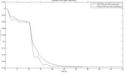
[image:7.612.310.529.124.167.2]From the simulation results can also be analyzed for the rotor angle changes as shown in Figure 9.
Figure 11. Rotor Angle Generator Response
From the picture above, the red graph shows the response of rotor angle when an interruption occurs without CES and PSS installed. While the blue graph shows the response of rotor angle using the CES and PSS. From both graphs can also be seen that the addition CES and PSS can reduce rotor angleoscillation due to a load changesdisturbance.Overshoot rotor angle data system single-machine generator are shown in the table below.
Table 5. Rotor Angle Overshoot Value
Without Controller (pu) CES and PSS (pu)
max min mean max min mean
1.098x1035 -0.176 -0.141 1.097x1035 -0.176 -0.136
Table 5 also indicates that, with the addition of CES and PSS in the system, making rotor angle overshoot becomes smaller.
c. Voltage Responses
[image:7.612.315.516.284.418.2]Analysis of simulation results of voltage parameters due to the installation of CES and PSS are shown in Figure 10.
Figure 12. Generator Voltage Responses
Based on thefigure 10, the red graph shows the voltage response when an interruption occurs without CES and PSS installed. While the blue graph shows the voltage response using CES and PSS. These images show that CES and PSS installation can reduce the voltage oscillation. However, overshoot that occurs due to theinstallation of CES and the PSS in the system becomes larger.
Overshoot voltage data in single-machine generator models are shown in the table below.
Table 6. Voltage Overshoot Value
Without Controller (pu) CES and PSS (pu)
max min max min
9.065 -0.2513 9.065 -0.2429
[image:7.612.95.298.452.574.2]ISSN: www.jatit.org E-ISSN:
4199
7. CONCLUSION
The results of proposed method showed that the installation of CES and the PSS in the single-machine generator models can reduce the oscillation due to load changes failure. The use of GA optimization algorithm parameters used as constants in the CES and PSS proved effective enough to get the optimum value so that the oscillation due to a disturbance becomes smaller. This will make the system safe from unwanted events. untuk kedepannya diharapkan penelitian ini dapat diimplementasikan pada sistem nyata.
REFRENCES:
[1] Sulistiawati, Irrine Budi, et al. "Critical Clearing Time prediction within various loads for transient stability assessment by means of the Extreme Learning Machine method." International Journal of Electrical Power & Energy Systems 77 (2016): 345-352.
[2] P. Kundur, et al, “Definition and classification of power system stability”, IEEE transactions on power systems, vol. 19, n.2, pp. 1387- 1401, 2004.
[4] Cheng, GUO dan LI Qun-zhan, “Simultaneous coordinated tuning of PSS and FACTS damping controllers using improved particle swarm optimization”, IEEE, 2009. [5] Miotto, E. L. dan M. R. Covacic, “Analysis
of Impacts of PSS Controllers and TCSC FACTS Devices at Dynamic Stability of a Multimachine System Power”, IEEE/PES Transmission and Distribution Conference and Exposition: Latin America, 2010. [6] Eslami, Mahdiyeh, Hussain Shareef, dan
Azah Mohamed, “Coordinated Design of PSS and TCSC Controller for Power System Stability Improvement”, IEEE IPEC, 2010. [7] Kanojia, S.S. dan V.K.Chandrakar,
“Coordinated Tuning of POD and PSS Controllers with STATCOM in Increasing the Oscillation Stability of Single and Multimachine Power System”, IEEE International Conference On Current Trends In Technology, 2011.
[8] S.C. Tripathy, I.P, Mishra,“Dynamic Performance Of Wind-Diesel Power System With Capacitive Energy Storage”, Energy Convers. Mgm Vol. 37, No. 12, 1996. [9] S.C. Tripathy, “Improved Load Frequency
Control With Capacitive Energy Storage”,
Energy Cottut-rs. hfgmt Vol. 38, No. 6. pp. S-562. 1997.
[10] Rajesh Joseph Abraham, D. Das and Amit Patra,” Automatic Generation Control of an Interconnected Power System with Capacitive Energy Storage”,International Journal of Electrical Power and Energy System Engineering 3:1 2010.
[11] Rajesh Joseph Abraham, D. Das & Amit Patra, “Effect of Capacitive Energy Storage on Automatic Generation Control”, The 7th International Power Engineering Conference (IPEC), 2005.
[12] Aribowo, Widi, “Desain Recurrent Neural Network Power System Stabilizers (RNN-PSS) Pada sistem Multi Mesin Jawa-Bali 500kV”, Tesis, Jurusan Teknik Elektro, Institut Teknologi Sepuluh Nopember, Surabaya, 2009.
[13] Saadat, Hadi, “Power System Analysis”, New York: McGraw-Hill, Inc, 1999.
[14] Guo Pengfei, Wang Xuezhi, Han Yingshi, “The Enhanced Genetic Algorithms for the Optimization Design” 3rd International Conference on Biomedical Engineering and Informatics, 2010.
[15] D. Karaboga, dan S. Okdem, “A Simple and Global Optimization Algorithm for Engineering Problems: Differential Evolution Algorithm”, TurkJElecEngin, VOL.12, NO.1, 2004
[16] Ram Krishan, Ashu Verma, Sukumar Mishra, An efficient multi objective optimization approach for robust tuning of power system stabilizers, Power Systems Conference (NPSC), 2016 National
[17] Sragdhara Bhattacharya, Power system oscillation damping by intelligent power system stabilizer, Power Electronics, Intelligent Control and Energy Systems (ICPEICES),IEEE International Conference, 2016
[18] Dhanraj Chitara, K.R. Niazi, Anil Swarnkar, Cuckoo Search Optimization algorithm for designing of multimachine Power System Stabilizer, Power Electronics, Intelligent Control and Energy Systems (ICPEICES),IEEE International Conference, 2016
4200 [20] C R Aswathi, Jeevamma Jacob, Power
system stabilizer for single machine infinite bus system for robustness against inertia constant variations, Advanced Communication Control and Computing Technologies (ICACCCT), 2016
[21] Pothula Jagadeesh, M. Sai Veerraju, Particle swarm optimization based power system stabilizer for SMIB system, Emerging Trends in Engineering, Technology and Science (ICETETS), International Conference 2016 [22] L. H. Hassan, M. Moghavvemi, H. A. F.
Almurib and K. M. Muttaqi, "A Coordinated Design of PSSs and UPFC-based Stabilizer Using Genetic Algorithm," in IEEE Transactions on Industry Applications, vol. 50, no. 5, pp. 2957-2966, Sept.-Oct. 2014 [23] Rakesh Rajan Shukla, Manoj Kumar
Maharana, Debapriya Das, Effect of CES and SMES on AGC in presence of different controllers and ramp disturbances, Power, Communication and Information Technology Conference (PCITC), 2015 IEEE
[24] Sandeep Dhundhara, Yajvender Pal Verma, Performance evaluation of Wind-Diesel Hybrid System with Capacitive Energy Storage system, India Conference (INDICON), 2015 IEEE
[25] Shan Tai, “An Improved Genetic Algorithm and its Blending Application with Neural Network” .2010.
[26] Priyadi, A., Yorino, N., Qudsi, O. A., & Purnomo, M. H. (2014, October). CCT computation method based on critical trajectory using simultaneous equations for transient stability analysis. In Information Technology and Electrical Engineering (ICITEE), 2014 6th International Conference on (pp. 1-6). IEEE.