http://dx.doi.org/10.4236/ijcns.2014.710045
Modeling and Simulation Study of Space
Data Link Protocol
Ismail Hababeh1, Rizik M. H. Al-Sayyed2, Ja’far Alqatawna2, Yousef Majdalawi2,
Marwan Nabelsi3
1Faculty of Computer Engineering and Information Technology, German Jordanian University, Amman, Jordan 2King Abdullah II School for Information Technology, The University of Jordan, Amman, Jordan
3Digital Signal Processing & Information Technology, Bremen,Germany
Email: [email protected], [email protected], [email protected], [email protected], [email protected]
Received 14August 2014; revised 10September 2014; accepted 8October 2014
Copyright © 2014 by authors and Scientific Research Publishing Inc.
This work is licensed under the Creative Commons Attribution International License (CC BY). http://creativecommons.org/licenses/by/4.0/
Abstract
This research paper describes the design and implementation of the Consultative Committee for Space Data Systems (CCSDS) standards [1] for Space Data Link Layer Protocol (SDLP). The primer focus is the telecommand (TC) part of the standard. The implementation of the standard was in the form of DLL functions using C++ programming language. The second objective of this paper was to use the DLL functions with OMNeT++ simulating environment to create a simulator in order to analyze the mean end-to-end Packet Delay, maximum achievable application layer throughput for a given fixed link capacity and normalized protocol overhead, defined as the total number of bytes transmitted on the link in a given period of time (e.g. per second) divided by the number of bytes of application data received at the application layer model data sink. In addition, the DLL was also integrated with Ground Support Equipment Operating System (GSEOS), a software system for space instruments and small spacecrafts especially suited for low budget missions. The SDLP is designed for rapid test system design and high flexibility for changing telemetry and command requirements. GSEOS can be seamlessly moved from EM/FM development (bench testing) to flight operations. It features the Python programming language as a configuration/scripting tool and can easily be extended to accommodate custom hardware interfaces. This paper also shows the results of the simulations and its analysis.
Keywords
1. Introduction
Traditionally, Telemetry (TM) [2] [3] transmitted from the spacecraft was formatted with a time division and multiplexing schema, where the data was multiplexed in a stream of fixed length data frames. Each spacecraft had its own data system, which was used only on a specific project. With the advancement of the microproces-sor-based spacecraft devices, we gained more flexibility and throughput to transmit data from spacecraft.
The proposed simulation method aimed at implementing the CCSDS standard Space Data Link Layer Proto-col into a dynamically loadable shared object (DLL). In addition, it is designed to use the library in a dis-crete-event simulator in order to test the library and to study the influence of the packet loss probability and channel capacity on the protocols performance.
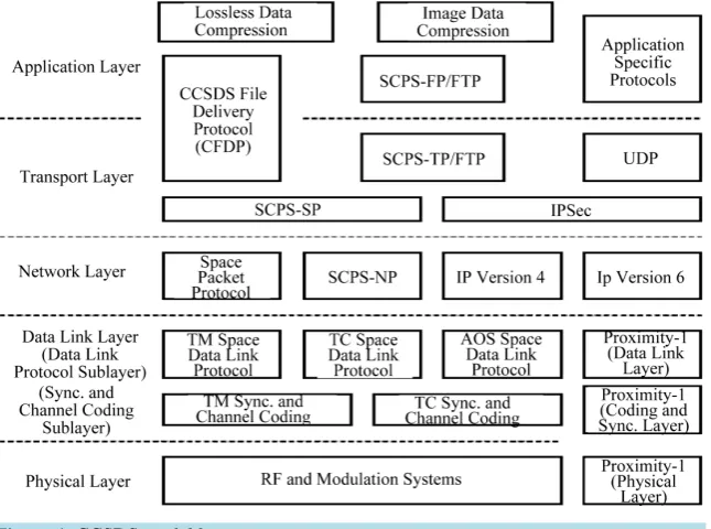
CCSDS began publishing standards starting with the Packet Telemetry protocol which could efficiently send packets from the spacecraft [3]. The standards set by CCSDS can be associated usually with five Open Systems Interconnection (OSI) reference model layers; as with most networks, the session and presentation layers are not associated.Figure 1 shows an overview of the CCSDS layers. CCSDS does not define an Application Pro-gramming Interface (API) but rather define primitives which are an abstract form of API and can be used as the baseline for an API.
For instance, the CCSDS standards of the physical layer that handle the Space Link between the spacecraft and the ground stations are:
• Radio Frequency and Modulation Systems.
• Proximity-1 Space Link Protocol that includes some functionality of the physical layer, also it contains Data Link Layer functionality.
Just like the OSI reference model, CCSDS has divided the Data Link Layer into two sub-layers: Data Link sub-layer and Synchronization and Channel Coding sub-layer:
For Data Link sub-layer, CCSDS defines four protocols [1] for this data link sub-layer: i) TM Space Data Link Protocol
ii) TC Space Data Link Protocol
iii) AOS (Advanced Orbiting Systems) Space Data Link Protocol
iv) Proximity-1 Space Link Protocol—Data Link Layer, which can also be referred to as SDLP
While for Synchronization and Channel Coding sub-layer, CCSDS defines three Synchronization and Chan-nel Coding sub-layers [3] [4]:
[image:2.595.154.477.470.710.2]i) TM Synchronization and Channel Coding
ii) TC Synchronization and Channel Coding
iii) Proximity-1 Synchronization and Channel Coding
There is no AOS Synchronization and Channel Coding layer as AOS uses the TM Synchronization and Channel Coding protocol. The SDLP uses Transfer Frames as its protocol data units, with the main task of trans- ferring the frames over a Space Link between the spacecraft and ground stations. Meanwhile the Synchroniza- tion and Channel Coding sub-layers provide functionality for error correction, detection, pseudo-randomization and frame Synchronization.
The goal of the Network Layer is to transfer packets from one end and to route them to a specific destination on the other end. The CCSDS standards of the Network Layer are: Space Packet Protocol, SCPS Network Pro-tocol and IP versions 4 and 6 with encapsulation.
The CCSDS standards of the transport layer are: SCPS Transport Protocol and CCSDS File Delivery Protocol (CFDP) that also provides application layer functionality.
The CCSDS standards of the application layer are: SCPS File Protocol (SCPS-FP), Lossless Data Compres-sion, Image Data Compression and CCSDS File Delivery Protocol (CFDP) that also provides transport layer functionality.
In this research, the implementation will be divided into two main parts: a library of functions for implement-ing CCSDS space data link protocol (SDLP) features, and the OMNeT-based simulation framework components for testing and studying the library functions. The TC Space Data Link Protocol Layer library will be imple-mented according to the requirements of the space communications protocols [1] to run simulations on a packet level. The physical channel will not be implemented and the data transfer will be simulated using a simple data channel from the OMNeT++ library which will simulate packet loss according to a probability provided as a simulation parameter. An additional requirement is the compatibility with the GSEOS testing environment and testing with a simple GSEOS script.
The rest of this paper is organized as follows: Section 2 reviews the space data link protocol related literature, Section 3 presents the Space Data Link Layer Protocol development. Section 4 describes space data link proto-col simulation and implementation. Section 5 describes the simulation analysis and results, and finally, the con-clusion is drawn in Section 6.
2. Literature Review
The Space Data Link Protocols are designed by CCSDS to meet the requirements of space missions for efficient transfer of space application data of various types and characteristics on space links [5].
CCSDS has developed four Space Data Link Protocols: the TC Space Data Link Protocol (TCSDLP, the TM Space Data Link Protocol, the AOS Space Data Link Protocol, and the Data Link Layer of the Proximity-1 Space Link Protocol [1].
The average end to end delay of data packets is the interval between the data packet generation time and the time when the last bit arrives at the destination [6]. It also includes the delay caused by route discovery process and the queue in the data packet transmission. Only the data packets that successfully delivered to destinations are counted. A lower value of the end to end delay means a better performance of the protocol.
The challenge of optimizing applications performance can be achieved by means of throughput maximization which leads to optimal performance for applications that are insensitive to delay and packet loss. A resource al-location can be found which maximizes the user satisfaction based on most opinion score. However, there is a possibility that even though the system performance is maximized, some users may not be satisfied as the opti-mizer can decide to allocate the resources to the other users. Therefore, scaling coefficients based on the maxi-mum average of the estimated most opinion score is considered to achieve maximaxi-mum applications throughput [7].
The normalized routing load is defined as the number of routing control packets transmitted per data packet delivered at the destination where each routing control packet transmission is considered one transmission [8].
A multi-path routing algorithm based on network coding can be used to ensure successfully packets transmis-sion and to minimize the number of packets retransmistransmis-sions by means of adding redundancy. A new retransmis-sion technique is used which retransmits data packets through intermediate nodes. It reduces long delay and high cost caused by retransmission [9].
channel. In this protocol, the receiver sends an acknowledgment for any correctly received packet. If the ac-knowledgment is not received by the transmitter within specified time period, the transmitter’s timer expires and the transmitter resends the presumably lost data message. Three basic types of the sliding window protocol have been used; stop-and-wait, go-back-N, and selective-repeat protocols. A performance simulator can be used to simulate the sliding window protocol simply by choosing appropriate transmit and receive window widths [10].
3. SDLP Development
The main aim of this research is to design and develop a software implementation of the CCSDS-standard space data link protocol transfer sub-layer, including the automatic repeat request-based reliable point-to-point re-transmission scheme. So, the section will mainly cover the SDLP software functional requirements, its output metrics and its model design.
3.1. SDLP Software Functional Requirements
The programmed software is designed to handle a library of functions for implementing CCSDS features, and the OMNeT-based simulation framework components for testing and studying the library functions.
• The library functions should include functions to implement the following features of the TC SDLP [11]: frame formatting, generation of headers and trailers, simple multiplexing/demultiplexing of data from multi-ple sources (decided only by an ID code) onto a physical channel, segmentation/blocking of large/small higher-layer data units and CCSDS Communications Operating Procedure-1 (COP-1) [12] features: retrans-mission of missing/out-of-sequence protocol data units/frames (Type A service only). However, the error control information generation/checking flow control features are not required for this research.
• The return link TM SDLP standard [3] frame format should be implemented to be able to provide feedback on frame reception to the frame sender Communications Link Control Word (CLCW mechanism); this re-quires only frame formatting and sending functions.
• The SDLP library functions should be compiled into a dynamically loadable shared object (DLL). • It should be possible to link the SDLP library functions into the OMNeT++ simulation framework [13]. • It should be possible to link the SDLP library functions into the GSEOS test environment. Integration into
GSEOS should be tested only briefly to verify that functions can be called correctly from a GSEOS script, no further verification is necessary.
• The OMNeT simulation model should include one of the existing simple communications channel models in OMNeT, which can simulate a fixed probability of packet loss and an appropriate propagation delay and throughput capacity for a satellite communications link (low-earth orbit or geostationary or both). This should be used to model a simple physical layer for a channel between two communication entities (ground station and satellite). Note: Channel access, modulation, Channel Coding and any other lower-layer schemes do not need to be modeled in this project which involves only packet-level and not bit-level simulation. The channel features are abstracted to a simple fixed packet loss probability, propagation delay and capacity, as already mentioned.
• The OMNeT simulation framework should include an application layer model to generate data packets with a fixed or (optional) random Poisson-distributed inter-arrival time and pass these down to the lower commu-nication protocol layers. The application layer model shall be able to receive data packets generated by an-other instance of itself (at the an-other end of the simulated link).
• The OMNeT simulation framework should include an integration layer to take packets from the application layer model and pass them through the SDLP-formatting and COP-1 functions in the library before passing them down to the physical layer model. The OMNeT framework shall use the library functions as passive functions; therefore all control of communicated packet flow is in the hands of the simulation framework. • The OMNeT simulation framework should be set up to enable the study of the output metrics as a function of
the packet loss probability or channel capacity (set in the channel model) at the minimum.
3.2. SDLP Output Metrics
ii) Maximum achievable application layer throughput for a given fixed link capacity.
iii) Normalized protocol overhead defined as the total number of bytes transmitted on the link in a given pe-riod of time divided by the number of bytes of application data received at the application layer model data sink.
iv) The DLL part of the project must also be compatible and usable with the GSEOS test environment.
3.3. SDLP Model Design
The proposed SDLP model is composed of two main parts, which are developed in two steps:
• The first step is the TC SDLP DLL which will contain most of its functionality as described by the CCSDS standards in reference document [2] in addition to some TM functions needed to return the CLCW from FARM-1. The required functionality from TC is given in reference document [1], and the TM functionality is described in document [3]. Although not all functions will be implemented from the Data Link Layer, the missing functions that would handle error control and flow control will either be simplified through the channel model in the OMNeT++ or it will not be part of the simulation, but this does not affect the main functionality of TC SDLP and COP-1.
• The second step of development will include building the OMNeT++ simulation part linking the DLL. The OMNeT++ program will be fully in charge of calling the TC SDLP functions in the correct sequence in order to simulate the work flow of the protocol, and to create the required parts in order to simulate the communi-cation between a ground station and a specific satellite (LEO, GEO) which will include message generator, sink and a channel model.
An important requirement of the DLL is to verify its compatibility with GSEOS. The compatibility will in-fluence the system design and data structures in order to achieve the compatibility. GSEOS uses a language called (g) which is similar to C. The verification part will be done by creating a simple GSEOS script and calling the DLL functions.
Implementing this system is the first part of this paper and the outcome simulation program will be used in the second part to conduct studies on the TC SDLP.
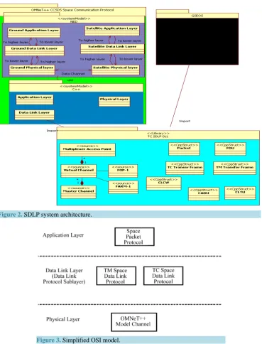
Figure 2 illustrates the three applications that are needed in order to complete this research. The figure shows both the GSEOS and the OMNeT++ simulation import the SDLP DLL functions, and each application shows its main components. The simulation by which OMNeT++ is depicted shows the ground and the satellite compo-nents. The message part of the OMNeT++ is represented as a data structure in the DLL, so it is not separately included in this figure. Meanwhile, GSEOS is a black box, the details provided on GSEOS will be limited to what is needed to prove that the DLL is integral with it. The DLL contains only functions and data structures are distributed in logically structured files.
Figure 3 shows a simplified OSI reference model in relation to this system’s layers.
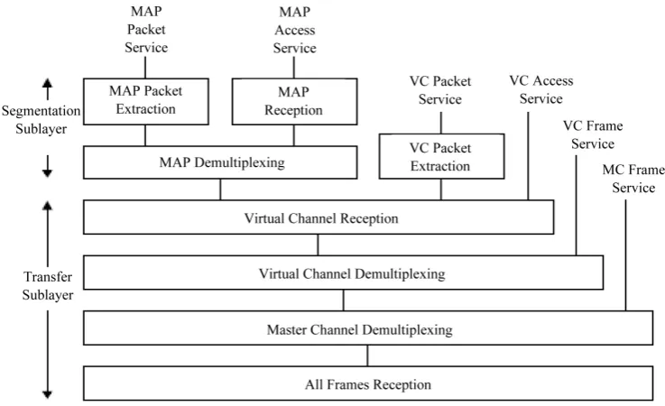
Figure 4 and Figure 5 show the main functions defined by CCSDS, DLL and the data structures that has been based on.
4. SDPL Simulation and Implementation
Following the implementation of the SDLP DLL, the DLL will be linked with the OMNeT++ simulation. In this context, a single Ground station will be created to simulate the sending side of the TC SDLP and the receiving side of the TM SDLP, and a single Satellite object will be created to simulate running the receiving end of the TC SDLP and the sending end of the TM SDLP.
The SDLP will contain one MAP with the ID 1, one Virtual Channel (VC) with the ID 1, one Master Channel (MC) with the Transfer Frame Version Number (TFVN) equal 1, the Spacecraft Identifier (SCID) equal to 1, and one PC with the name 1. The channels are defined as global variables in the Data Link Layer class. On startup, OMNeT++ calls the initialize function from the DataLinkLayer class object, setting the initial values of the channels.
The work flow was implemented in order to use most of the entities defined in the internal organization by CCSDS as shown in Figure 4, therefore the Data Link Layer will receive a packet. Resulting in calling the MAP processing, although only a single MAP, VC, MC and PC exists the work flow still used the multiplexing func-tions. A full description of each layer will be presented; showing how the work flows of the SDLP was imple-mented using the DLL.
Figure 2.SDLP system architecture.
Figure 3. Simplified OSI model.
The tasks of controlling COP and calling the management services was also given to this layer, to the gener-ating packets, handle received alerts from COP and in addition to receiving the packets on a receiving side ob-ject (Satellite). This class uses the ned parameters in the AppLayer.ned simple module. These parameters are used to differentiate between the Ground Station and the Satellite. In addition, the parameters allow the user to specify the type of initialize directive that will start the COP.
Figure 6 shows the startup simulator form where users can select the directive request they wish to initialize the COP with.
The Data Link Layer defined as a class called Data Link Layer. The tasks of controlling sending and receiv-ing of both TM and TC transfer frames falls on this layer in addition to blockreceiv-ing and segmentreceiv-ing of packets and creating the TM and TC transfer frames.
Figure 4. Simplified internal organization of the TC SDLP protocol entity (sending end).
Figure 5. Internal organization of the TC SDLP protocol entity (receiving end).
[image:7.595.128.497.296.521.2]For implementation and in accordance with the software functional requirements, the DLL was integrated with GSEOS and tested; the tests resulted in success after minor modifications to the DLL. The errors were caused due to the different way method GSEOS handled bit fields. Unlike the C++ compiler GSEOS did not perform bit alignment therefore the sizes of some data structures did not match, and hence it resulted in the data being shifted, and thus returned inaccurate results. This problem, once identified, was easily fixed by manually adding extra bits in data structure to align them to 1 byte. Additionally, the time-out functions were handled by OMNeT++ which was not implemented with GSEOS.
5. Simulation Analysis and Results
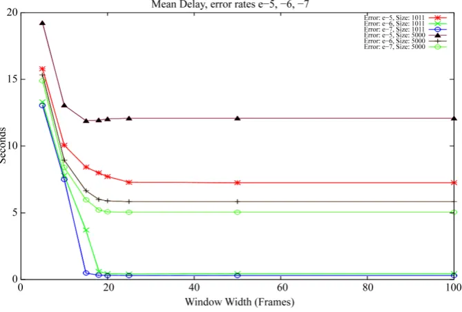
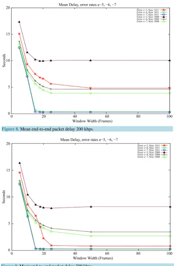
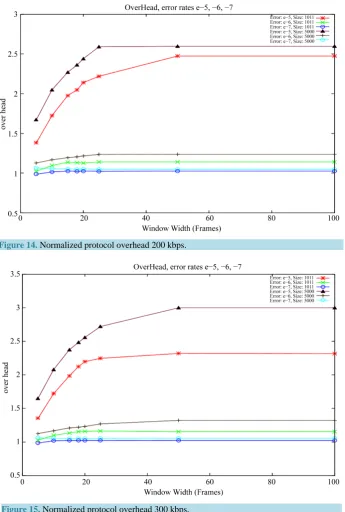
In accordance with the software functional requirement where the OMNeT simulation framework should be set up to enable the study of the output statistics as a function of the packet loss probability or channel capacity, the resulted software was used to generate data with different parameters in order to study the mean end-to-end packet delay, maximum achievable application layer throughput for a given fixed link capacity normalized pro-tocol overhead. The AD service and the following parameters are used to generate the graphs depicted in Figures 7-15.
• Bit Error Rate, with the following three variations: 1e−5, 1e−6, 1e−7. • Max Packet Size, with the following two variations: 5000, 1011 bytes. • Window width, the following values were used: 5, 10, 15, 18, 20, 25, 50, 100. • Data Rate, the following values were used: 150 kbps, 200 kbps, 300 kbps. • Delay 250 ms.
• Number of packets to Transmit, the value 100000 was used. • CLCW report period was set to 300 ms.
• Range of uniform distribution for packet generations [0, 0.1]. • Initializing directive: Initiate AD service (without CLCW).
The mean packet size for the maximum 5000 bytes packets was an average of 2510 bytes, as for the 1011 maximum packet size had a mean of 510 bytes.
For the Mean end-to-end Packet Delay measurements, Figures 7-9 show that the idle window size between 15 and 20 have the minimum delay, and the delay remains approximately the same after increase the window size.
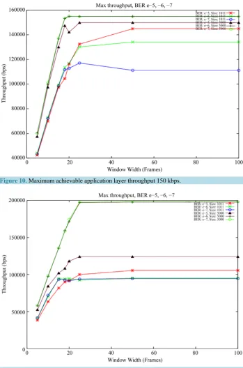
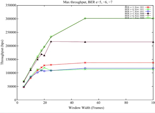
[image:8.595.147.482.477.703.2]For the Maximum Achievable Application Layer throughput measurements, Figures 10-12 show the window sizes with which we can achieve the maximum throughput. The figures show the highest throughout at lower
Figure 8. Mean end-to-end packet delay 200 kbps.
Figure 9. Mean end-to-end packet delay 300 kbps.
error rates as expected, the reason why the 1011 and 5000 packets differ is because the 1011 packets do not generate enough traffic to allow the network to reach maximum capacity. The window width that leads to the highest throughput differ from each speed by a little, this is due to how many packets we can send before reach the link capacity.
Figure 10. Maximum achievable application layer throughput 150 kbps.
Figure 11. Maximum achievable application layer throughput 200 kbps.
All these results are summarized in Table 1. The best and the worst values for each metric (mean end-to-end packet delay, maximum achievable application layer throughput and normalized protocol overhead) are com-pared numerically for the five factors: data rate (kbps), bit error rate, packet size (bytes), window width (frames) and value with its units.
6. Conclusion
[image:10.595.137.489.85.348.2]Figure 12. Maximum achievable application layer throughput 300 kbps.
Figure 13. Normalized protocol overhead 150 kbps.
Table 1. Summary to simulation results.
Measurements
Factors
Data rate (kbps)
Bit error rate
Packet size (bytes)
Window width
(frames) Value/Unit Mean end-to-end
packet delay
Best values 300 1e−7 1011 >=15 0.50 sec
Worst values 150 1e−5 5000 >=15 12.50 sec
Maximum achievable application layer throughput
Best values 300 1e−6 1011 >=50 300,000 bps
Worst values 200 1e−7 1011 >=15 90,000 bps
Normalized protocol overhead
Best values All data rates 1e−7 1011 >=5 1 packet
[image:11.595.87.540.615.723.2]Figure 14. Normalized protocol overhead 200 kbps.
Figure 15.Normalized protocol overhead 300 kbps.
the TC SDLP with COP-1 retransmission mechanism. It allowed the user to run simulations in order to analyze the performance using a variety of parameters. In addition, this implementation proved a successful integration with GSEOS for use in EGSE software.
References
[1] (2007) Overview of Space Communications Protocols. Issue 2. Report Concerning Space Data System Standards, CCSDS 130.0-G-2. Green Book. CCSDS, Washington, D.C.
[3] (2011) TM Synchronization and Channel Coding. Issue 2. Recommendation for Space Data System Standards, CCSDS 131.0-B-2. Blue Book. CCSDS, Washington, D.C.
[4] (2010) TC Synchronization and Channel Coding. Issue 2. Recommendation for Space Data System Standards, CCSDS 231.0-B-2. Blue Book. CCSDS, Washington, D.C.
[5] (2007) Proximity-1 Space Link Protocol—Rationale, Architecture, and Scenarios. Report Concerning Space Data Sys-tem Standards, CCSDS 210.0-G-1. Green Book. Issue 1. CCSDS, Washington, D.C.
[6] Kushwah, V.S., Chauhan, K.K. and Sanger, A.K.S. (2010) A Comparative Study of Mobile Ad Hoc Network Protocols for Throughput, Average End-to-End Delay and Jitter. International Journal of Computational Intelligence Research, 6, 385-393.
[7] Khan, S., Duhovnikov, S., Steinbach, E., Sgroi, M. and Kellerer, W. (2006) Application-Driven Cross-Layer Optimiza-tion for Mobile Multimedia CommunicaOptimiza-tion Using a Common ApplicaOptimiza-tion Layer Quality Metric. Proceedings of the 2006 International Conference on Wireless Communications and Mobile Computing, ACM, 213-218.
[8] Pei, G., Gerla, M. and Hong, X. (2000) LANMAR: Landmark Routing for Large Scale Wireless ad Hoc Networks with Group Mobility. Proceedings of the 1st ACM International Symposium on Mobile ad Hoc Networking & Computing IEEE Press, 11-18.
[9] Yu, G., Zhong, C., Lan, X., Zhang, C., Wei, L. and Liu, Y. (2014) Research of Multi-Path Routing Based on Network Coding in Space Information Networks. Chinese Journal of Aeronautics, 27, 663-669.
http://dx.doi.org/10.1016/j.cja.2014.04.009
[10]Hercog, D. (2010) The Importance of Sliding Window Protocol Generalisation in a Communication Protocols Course. International Conference on Engineering Education ICEE, Gliwice, 18-22 July 2010.
[11](2010) TC Space Data Link Protocol. Issues 2. Recommendation for Space Data System Standards, CCSDS 232.0-B-2. Blue Book. Issue 2. CCSDS, Washington, D.C.
[12](2010) Communications Operation Procedure-1. Issue 2. Recommendation for Space Data System Standards, CCSDS 232.1-B-2. Blue Book. CCSDS, Washington, D.C.