A Reduced Order Transfer Function Models for
Alstom Gasifier using Genetic Algorithm
Anitha Mary.X
Research Scholar,Department of Electronics and Instrumentation Engineering, Karunya University, Coimbatore,
India.
L.Sivakumar
Vice Principal and HOD of Mechantronics, Sri Krishna College of Engineering, Coimbatore.
Formerly General Manager, Corporate R&D, BHEL, Hyderabad, India.
ABSTRACT
ALSTOM has thrown a challenge problem related to the control of MIMO gasifier which is a nonlinear system. Quite a few researchers have tried different methods for control tuning and found that critical process transients such as pressure and temperature of syngas during specified load changes are not within the desired limits. This is mainly attributed to a very high order of the gasifier system. Due to this, efforts have been made to represent gasifier higher order models as a simplified lower order models. This paper focuses on identifying a reduced order transfer function models for gasifier with minimum IAE and ISE error criterion using Genetic Algorithm. The lower order transfer functions obtained using Genetic Algorithm is found to be superior to those obtained using RGA loop pairing and Algebraic method proposed respectively by Haryanto and Sivakumar et.al.
Keywords:
Gasifier, Reduced order transfer function, Algebraic Method, Genetic Algorithm, MIMO Systems.
1.
INTRODUCTION
Integrated Gasification Combined Cycle (IGCC) is being developed all over the world to provide higher conversion efficiency than the conventional power generation with reduced pollutant emissions. Here coal is converted into fuel gas which in turn is used to produce electricity. The ALSTOM gasifier, one of the components in IGCC is found to be a complicated nonlinear process. Two challenges were issued by ALSTOM in 1997 and 2003 respectively. The objective of the challenges is to design a controller for gasifier which satisfies the performance criteria viz pressure and temperature transients of syngas to be well within the specified limits during load changes. The controllers like predictive control[3] multi objective optimitization [4], proportional integral plus control [5], multi objective optimal tuning PI controller design [6], H∞ control [7], process engineering approach[8],
researchers to obtain lower order transfer function models. It is observed that Haryanto et.al., [14], Sivakumar and Anitha Mary.X [15], Sivakumar and Koteeswaran [16] developed lower order transfer function models for ALSTOM MIMO system. The low order transfer function models developed by authors [15] using algebraic method are found to be better approximation than those by Haryanto et.al., and reflects the characteristics of original higher order system. However, four transfer functions out of sixteen transfer functions obtained by Algebraic method are having higher error than those by Haryanto et.al, This paper extends the work of authors [15] using genetic algorithms to obtain reduced order transfer functions with minimum ISE and IAE error.
2.
GASIFIER DESCRIPTION
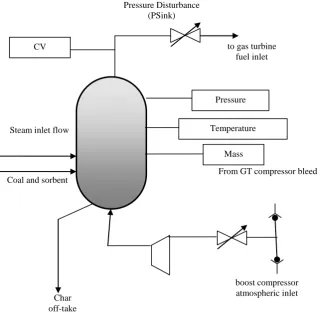
ALSTOM gasifier consists of 5 input and 4 output system. Char extraction flow rate (u1), air flow rate (u2), coal flow rate (u3), steam flow rare (u4) and limestone flow rate (u5) are the controllable inputs, Syngas calorific value (y1), bed mass (y2), pressure (y3) and temperature (y4) are the controllable output. Limestone and coal are added in the ratio of 1:10. This leaves gasifier with 4x4 MIMO system.Figure 1 shows the ALSTOM gasifier with input and output variable.
The ALSTOM gasifier is modeled in state space form as given by
Ẋ= Ax+Bu Y=Cx+Du Where
x = Internal states of gasifier, a column vector with dimension 25x1
u = Input variables, a column vector with dimension 6x1 A = system matrix governing the process dynamics, a square matrix with dimension 25x25
B = Input matrix with dimension 25x6
Fig 1: ALSTOM Gasifier
3.
HIGHER
ORDER
TRANSFER
FUNCTION MODELS
On analyzing the ALSTOM gasifier model, the model is found to be more complex and it contains very high cross-coupling between input and output [10]. The state space equation is converted to transfer function models using MATLAB command sys = ss(a,b,c,d) and [num,den]=ss2tf(a,b,c,d,1). After conversion by Matlab command, the system is described in s- domain as follows:
=
Where
yi(s) = output variables ; i={1,4 }
Gij(s) = transfer characteristic between jth output due to ith input ; i= {1,4} ; j={1,4}
ui(s) = input variable ; i={1,4}
It is to be noted that the denominator polynomial of each element Gij is of 24th order while the numerator is of order
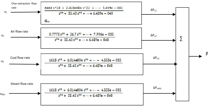
less than or equal to 23rd. A typical transfer characteristic between an output (syngas pressure) due to all inputs is shown in block diagram as in figure 2.
Pressure Disturbance (PSink)
to gas turbine fuel inlet
From GT compressor bleed
boost compressor atmospheric inlet Steam inlet flow
Coal and sorbent
Char off-take
Pressure
Figure 2 Transfer characteristic between pressure due to all inputs
P(t) = Psteady state+∆Pu1 + ∆Pu2 + ∆Pu3+ ∆Pu4
Here ∆Pui is the incremental change due to different inputs
ui. Thus
∆Pu1 is the incremental change in pressure due to steady
state change in char extraction flow rate,
∆Pu2 is the incremental change in pressure due to steady
state change in Air flow rate,
∆Pu3 is the incremental change in pressure due to steady
state change in Coal flow rate and
∆Pu4 is the incremental change in pressure due to steady
state change in steam extraction flow rate. The output is given below
Now the problem boils down to the reduction of higher order transfer function models obtained by MATLAB command to lower order transfer function models by the application of algebraic method and genetic algorithm.
4.
ALGEBRAIC METHOD
The higher order transfer can be equated with second order transfer function.
On cross multiplying, the equation becomes
A0 =
Taking appropriate value of A0, equating the powers of s,
and solving the equation the unknown values of B0, B1, A1, A2 can be obtained. Appendix 1 gives the lower order transfer function models using Algebraic method. The errors on the basis of IAE (Integral Absolute Error) and ISE (Integral Squared Error) are computed for each transfer function block obtained by algebraic method and RGA loop pairing aare taken over a period of time (little above the rise time). Table 1 shows the IAE and ISE error criterion for the lower order transfer functions using Algebraic method, and transfer function obtained using RGA loop pairing for 100% load[15]. During the process of identifying transfer function, the ISE and IAE associated with the transfer characteristics of :
First output with second input ie.,(G21) First output with third input ie.,(G31) First output with fourth input (G41) Third output with first input (G13)
are seems to be very high. It would be better if we avoid G31
∑
P
∆Pu3∆Pu2
∆Pu1
∆Pu4(t)
u1
u2
u3
u4(t)
Char extraction flow rate
f
Air flow rate
Coal flow rate
TABLE 1:IAE AND ISE ERROR CRITERION FOR ALGEBRAIC AND RGA LOOP PAIRING METHODS
Transfer function
Integral Absolute error Integer Squared error
TF obtained using Algebraic method
TF obtained using RGA loop pairing method
TF using Algebraic method
TF using RGA loop pairing method
G11 1644 1.087e+004 2.16e+006 1.455e+007
G12 7.09 2.954e+005 7.606 1.12e+010
G13 4.828e+004 8.039e+004 7.98e+008 7.784e+008
G14 5.096 2.308e+005 5.85 6.955e+009
G21 2.868e+005 8.71e+004 1.157e+10 8.637e+009
G22 11.5 20.97 20.74 57.78
G23 50.56 6.8e+004 1018 5.145e+008
G24 73.09 114.2 1412 2555
G31 9.128e+006 8.799e+006 2.166e+13 2.519e+013
G32 0.4021 6.277e+004 0.0362 4.58e+008
G33 35.04 9250 283.1 9.1e+006
G34 2.549 1.086e+005 0.8598 1.344e+009
G41 1.437e+007 1.434e+007 8.005e+13 7.98e+013
G42 15.18 2.695 39.14 1.213
G43 462.3 1.133e+005 3.812e+004 1.46e+009
5.
GENETIC ALGORITHM
In recent years, evolutionary computation has extented its growth in engineering field especially in optimization problems[19]. Genetic Algorithm is one such optimization tool and found to give better lower order approximation that reflects the characterization of higher order system. LOWER ORDER MODELLING:
Appendix 2 gives the auxiliary scheme for low order model [18]
The ALSTOM higher order transfer function for G13 is given below:
G13=
The second approximation is given as [18] G13=
The transient and steady state gain for G13 is TG/G13(s) = = -1.1
SSG/ G13(s) = = 4.0997e+04
The auxiliary scheme given in appendix 2 is used to find R(s) from G(s)
R(s) =
The above equation should be tuned to satisfy the transient and steady state gain so that R(s) reflects the characteristics of G(s)
R(s) =
=
The parameters B0 = -7.4137631e-04, b1= 2.081e-04 and b0= 1.8083624e-08 are used as seed value for genetic algorithm with ISE error as the objective function. The ISE error (E) can be obtained by taking the sum of the square of the difference between the step response of higher and lower order transfer function. The ISE error is given by
E= - )2
where, Yt is the unit step time response of the higher order system at the tthinstant in the time interval 0≤ t ≤τ, where τ is to be chosen and ytis the unit step time response of the lower order system at the tth time instant. The matlab commands
options =gaoptimset('InitialPop', [B1 B2 B3])
Optimal values found
Yes
Start
represents the higher order transfer function
Calculate the transient gain and steady state gain for G(s)
Apply lower order reduction in Appendix 2 to get R(s)= and tuned to maintain the transient gain of G(s)
Find the unit step response of G(s) and R(s) and calculate the ISE error E= - )2
Invoke genetic algorithm . Apply B0,b1,b0 values as initial population
Using the optimized value of B0,b1,b0 find the ISE and IAE error between R(s) and G(s)
stop
Evaluate fitness, perform selction, apply crossover to get new population and perform mutation
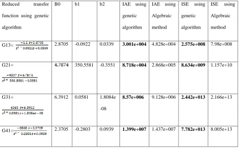
Table 2: Reduced errors due to genetic algorithm in the evaluation of G13,G21,G31,G41
Reduced transfer
function using genetic
algorithm
B0 b1 b2 IAE using
genetic
algorithm
IAE using
Algebraic
method
ISE using
genetic
algorithm
ISE using
Algebraic
method
G13= 2.8705 -0.0922 0.0339 3.001e+004 4.828e+004 2.575e+008 7.98e+008
G21= 350.5581 -0.3551 8.718e+004 2.868e+005 8.634e+009 1.157e+10
G31= 6.3912 0.0581 1.8084e
-08
8.57e+006 9.128e+006 2.442e+013 2.166e+13
G41= 2.3705 -0.2803 0.0939 1.399e+007 1.437e+007 7.782e+013 8.005e+13
6.
CONCLUSION
The development of low order transfer function models are required due to the difficulties encountered in the development of control strategies for the benchmark problem proposed by ALSTOM. In this direction, the authors have developed low order transfer function models using Algebraic method and reduced order approximation. The performance of these models has been evaluated on the basis of ISE and IAE error criteria. It is observed that the low order models derived using algebraic methods is much superior to one proposed by Haryanto et.al.Some lower order transfer functions obtained using algebraic method are found to have higher error than those obtained by RGA loop pairing method. Using Genetic Algorithm these errors are minimized and it is believed that the models proposed by algebraic method with Genetic Algorithm will become basis for further research on Gasifier control.
7.
ACKNOWLEDGEMENTS
The authors would like to express their thanks to Karunya
control engineering journal IEE vol 10 N0 3 pp 93-96, 1999.
[3] Rice M,Rosster.J and schurmans J An advanced predictive control approach to the Alstom gasifier prolem, proc, Inst.Mech Eng.I,J.System control Eng., 2000,214 pp.405-413.
[4] I.A.Griffin, P.Schroder, AJ Chipperfield and PJ Fleming multiobjective optimization approach proc, Inst.Mech Eng.I,J.System control Eng., 2000,214 pp.453-468.
[5] CJ Taylor, AP Mccabe,PC young and A chotai Proportional integral plus control of Alstom Gasifier problem proc, Inst.Mech Eng.I,J.System control Eng., 2000,214 pp.469-480.
[6] GP Liu, RDixon S Daley, multiobjective optimal tuning proportional integral controller design for the Alstom Gasifier problem proc, Inst.Mech Eng.I,J.System control Eng., 2000,214 pp.395-404. [7] E.Prempain, I.Postlethwaite and XD sun Robust
[10]Dixon R Alstom Benchmark challenge II: control of Nonlinear Gasifier model, 2002. http://www.iee.org/omcomms/PN/controlauto/Specifi cation_v2.pdf
[11] Dixon R, Becnhmark challenge at control, 2004, Comput. Control Eng IEE vol 10 No3 pp 21-23 2005.
[12] R.K. Seyab, Y.Cao and S.H Yang, The second alstom benchmark challenge on gasifier control predictive control for the ALSTOM gasifier problemIEE proceedings on control theory, vol153, N03 May 2006.
[13] Xi9n Wang, Ke Wu, Jianhong Lu, Wenguo Xiang, Non linear identification of Alstom gasifier based on wiener model International conference on sustainable power generation and supply pg 1-7 april 2009. [14]A. Haryanto, P.siregar, D.Kurniadi and Keum-shik
Hong, Development of Integrated Alstom gasification Simulator for implementation using DCSCS 3000 proceedings of the 17th world congress The international conference federation of automatic control, seoul, korea 2009.
[15] L.Sivakumar, Anitha Mary.X A low order transfer function model for MIMO ALSTOM gasifier, International conference on process Automation, Control and computing, IEEE 2011.
[16] L.Sivakumar, R. Koteeswarn, Linear Identification of Nonlinear MIMO system-Alstom Gasifier First international conference on modern trends in instrumentation and control, 2nd and 3rd September 2011.
[17] P.Poongodi, S. Victor Genetic algorithm based PID controller design forLTI system via reduced order model, International Conference on Instrumentation, Control & Automation ICA2009 October 20-22, 2009, Bandung, Indonesia.
[18]S.N. Sivanandam, S.N.Deepa, A Comparative Study Using Genetic Algorithm and Particle Swarm Optimization for Lower Order System Modelling International Journal of the Computer, the Internet and Management Vol. 17. No.3 pp 1 -10, (September - December, 2009)
[19] Melanie Mitchell, An introduction to Genetic Algorithm, Prentice-Hall of India NewDelhi, Edition: 2004.
APPENDIX 1
Transfer function matrix of ALSTOM
plant using algebraic method
G11=
G12=
G14=
G21=
G22=
G23=
G24=
G31=
G32=
G33=
G34=
G41=
G42=
G43=
G44=
APPENDIX 2
Lower order Transfer function
reduction
:Consider an nth higher order system represented by its transfer function
G(s) = =
=
First Order = ………(1)
Second order = …………(2) .
.
n-1 order = --
---(3)