3685
NEW MICROSTRIP FILTER FOR MIMO WIRELESS AND
COMPUTER SYSTEMS
1Aqeel H.Al-fatlawi, 2Mohammed A.Taha
1Department Of Computer Techniques, Imam Kadhum University College, Iraq
2Computer Technical Engineering Department, Islamic University College, Najaf, Iraq 1[email protected], 2[email protected]
ABSTRACT
This paper proposes new microstrip bandpass filter to prevent the image bands as far as possible for MIMO antenna configurations for IEEE 802.11 b wireless networks. The insertion loss and return loss values of the projected filter are 0.4 dB and 26.4 dB correspondingly that are very applicable to be implemented with MIMO antenna configuration.
This enhanced MIMO prototypical structure can significantly develop wireless scheme by using the multipath propagation productively. These enhancements can be utilized to augment the dependability of instantaneously communicated data streams, improve the wireless system capacity (multiplexing gain) and lessen the bit error rate of wireless system. Along with filter frequency response, the augmentations are investigated in terms of phase response, group delay and Bit Error Rate (BER) for various antenna configurations using QPSK digital technique.
Keywords: MIMO, Microstrip Bandpass Filter, Wireless and Computer Networks, IEEE 802.11 b, Bit Error Rate
1. INTRODUCTION
Wireless schemes are promptly growing sections
of the communications industry, with the approaching to make accessible, speedy and excellent information exchange amid useful devices located anywhere in the world. It has been the study theme from 1960s, the noteworthy development of wireless communication technology is for the reason that a combination of numerous influences. Initially, the necessity of the wireless connection is intensified greatly. Additionally, the remarkable innovation of VISL equipment has stimulated low-power and compacted carrying out of complicated code and signal processors. Also, 2nd generation ofwireless criterions as in GSM, makes it realisable to transfer voice and small capacity of digital data. Additionally, the 3rd generation of wireless
communications can provide clients of advanced service quality that completes superior spectral efficiency and capacity [1].
Forthcoming uses switched on by wireless systems have interactive program services on cellular phones, trendy homes, high-tech main road systems, video conversing and automated sensor networks. Conversely, there are dual foremost industrial confronts in reinforcing these appliances:
the 1st one is the fading incidence: the time
deviance of the channel owing to the small-scale outcome of multi-path fading, in addition to large-scale effect like pass loss by remoteness attenuation and obstructions shadowing. Secondly, as wireless transmitter and receiver involve a communication over the air, there is notable interfering amid them. Entirely, the challenges are principally due to constrained approachability of radio frequency range and a complex time-varying wireless setting. Presently, the focal intention in wireless communication is to augment data rate and expand communication steadfastness. Namely, because of the rising request for elevated bit rates, upgraded service quality, smaller amount of errors, superior network proficiency and user coverage calls for resourceful practices that expand spectral efficiency and link dependability, progressively wireless communication technologies are introduced as in Multiple Input Multiple Output (MIMO) techniques [2].
ISSN: 1992-8645 www.jatit.org E-ISSN: 1817-3195
3686 expansion in this design is not mandatory. The whole upcoming response from the reception to the transmitting antennas and its computing complication level are matching to MRC.
A radio channels measurements configuration comprising polarization and space dimensions to inspect the radio communication in wideband mobile systems was stated in [4]. The developed measuring systems were implemented by carrying out channel determination at 2 GHz and investigating the tentative data was certified. Besides, an extensive analysis regarding the spatial channels in mobile and base stations along with the double-directional link which absolutely exemplifies the propagation concerning dual antennas was introduced.
An investigation of the data transmission over the mobile radio channel was accomplished in [5]. A software radio receiver (SRR) project and simulated model was introduced. Also, an expansion of this SRR over the mobile radio link was investigated. Equalizing and diversity methods were applied to augment the performance of the data transmission. Selection Switching Combining (SSC) diversity technique was aopted in the project investigation.
Krishnamurthy studied the electromagnetic waves characteristics of antennas and the scattering adjusting along with data capability, the limitations of estimation procedures at the receiver termination and the evaluated capacity that influences the volume-limited multiple-antenna systems. Theoretic means were used to create a channel communication system for manifold antennas in the manifold fading channels [6].
In [7], MIMO test-bed was projected by utilizing a 2-antenna spreader and a 4-antenna receiver in ”offline” style, where pre-processed data is directed over-air and listed for future handling. The receiver allows 512 Mbytes of memory for each receiveing antenna and supreme sampling frequency of 100 MHz, that produces a logging period of 2.68 second with 14-bit resolution. This study is in accordance with Sundance’s modular digital signal processing and plug-in Radio Frequency (RF) mechanisms made by Mini-Circuits. Microstrip bandpass filters at ISM band was used to avert harmonic bands and boost MIMO test-bed operation.
Two depictions of antenna selection in Rayleigh channels using Orthogonal Space-Time Block Code technique (OSTBC) and Maximal Ratio Transmission (MRT) was exploited in [8]. Simulations have shown that the proposed antenna selection system can attain an output response close
to the optimal selection with small level of complexities.
Lozano and Jindal were given the focal adjustment features concerning sending antenna diversity and spatial multiplexing. The variation amongst the transmission approaches which employ wide-ranging spatial multiplexing and MIMO for diversity standards have been clarified [9].
An expansion of OFDM system using Space Time Block Coding (STBC) and MIMO procedures were exhibited over Rayleigh channels via 2PSK and QPSK digital modulations to overwhelm sub-channel interfering in [10]. The simulations disclosed that SNR rises with the lessening in bit error rate but it lessens by the intensification in the scheme throughput.
New microstrip filters were structured as miniature devices for contemporary wireless networks using fractals as reported in [11-13]. All filters exhibit narrow frequency responses with image band suppression at 2.4 GHz operating frequency. Those filters are suitably adopted for MIMO wireless networks.
Here, the MIMO wireless IEEE802.11bmodel uses new narrow band microstrip BPF to block the harmonic bands for these antennas during communication process. This filter stands for an anti-aliasing filter to overwhelm all spurious signals. The S11 and S21 responses of the suggested filter are extremely appropriate for MIMO wireless IEEE802.11bmodel. Based on this applied filter, the resultant phase response, group delay and bit error rate are considered in this study.
2. STBC MATHEMATICAL EQUATIONS
Presuppose a MIMO wireless IEEE802.11b
model with sending antennas and receiving antennas symbolized by N and M respectively. Flat fading channel is considered through the propagation gainhmn,l, where n, m, and l stand for transmitting antenna, receiving antennas, and period. hmn,l is a Rayleigh distributed random variable, autonomous complex Gaussian with variance 0.5 per category.The code matrix is possibly defined by C and the space-time block code time period is L. Let's assume T is the symbol interval, the arriving signal vector at the receiving antenna m at time lT is computed by [1,14,15]:
N
n
l m n l l mn l
m h c n
r
1
, , ,
, , (1)
3687 n
l
c, is the (l,n) constituent of the L by N code matrix C, and nm,l is related to an additive white complex Gaussian noise term with zero-mean and variance 2. For quasi-static channel, the time
index l in hmn,l can be misplaced.
T,
*,
H are signified as the transpose, the complex conjugate, and the Hermitian transpose, respectively. The collected signal vector at receiver side based on Eq. (1) can be represented by:N CH
R T , (2)
R, H, N stand for an L by M matrix with the (l,m) constituent rm,l, an M by N channel matrix with the (m,n) constituent hmn, and an L by M noise matrix, respectively.
Accordingly, it is tricky to realize signal processing procedures for this matrix depiction in Eq. (2), since C is commonly not itemized as a linear arrangement of the STBC input symbols. Furthermore, Eq. (1) cannot be altered into Eq. (2) for non-quasi-static channels. Then, it is important to formulate all-purpose expression irrespective to the code constituents or the channel state. With the object of adopting signal processing procedures, it is essential to use a linear superposition form:
n z H
r (3)
r points to the LM by 1 received signal vector, z is recognized as the K by 1 sent signal vector
TK z
z1 , H is the LM by K channel matrix, and n stands for the LM by 1 noise vector.
There are numerous STBC arrangements that can be reformed into a linear superposition organization. The code matrix C for the Alamouti orthogonal scheme [3] can be represented by:
*
1 * 2
2 1
z z
z z
C .
This code can be changed into a linear superposition formula in this subsequent method. By defining the conjugate of the 2nd part of the
received signal, the linear superposition formula for the Alamouti scheme is possibly stated as:
* 2 1 2 1 *
2 , 1 *
2 , 2
1 , 2 1 , 1 * 2 1
n n h
h h h r
r
z z
l
r, hn,l, and nl are M by 1 column vectors at time
lT and are stated as [r1,l r2,lrM,l]T, T
l Mn l
n l
n h h
h ]
[ 1, 2 , , , and
T l M l
l n n
n ]
[ 1, 2, , , respectively.
The finest detecting for the Alamouti technique for quasi-static channels is possibly prepared by simply multiplying the vector r by HH and regulating the symbol by symbol detector. The comprehensive Maximum Likelihood (ML) search can be denoted as an wide-ranging investigation for an equation solution,minrHz 2, by checking each likely set of transmitting symbols.
Nevertheless, for widespread STBC arrangements, it is impracticable to produce a complex linear superposition for Eq. (3). Such as for N=4 antennas arrangements, we start to have a rate 3/4 for C matrix [12] as:
1 * 2 * 3
2 * 1 *
3
3 *
1 * 2
3 2 1
0 0
0 0
z z z
z z z
z z
z
z z z
C (4)
This C matrix is not exchangeable to a multifaceted linear superposition structure as done in the Alamouti code. Then, if matrix facets are defined to real and imaginary amounts disjointedly, the collected vector is possibly written in a real linear superposition formula. As a rule, each block code is designated by this method by distributing real and imaginary constituents. This is referred as the lattice version.
3. LATTICE VERSIONS FOR STBC SCHEMES
A broad assembly of the lattice of higher orders version for the STBC outlines is given in this section. To form the real lattice channel matrix, C matrix is divided into dual constituents as
] [
~ CR CI
C where
R and
I are the real and the imaginary vector amounts as in zk xk jyk. Supposing that the (l,n) constituent of C signifiesk k
n
l c x jc y
c, 1 2 , where c1 and c2 are constant
amounts. Subsequently, the lth row vector of CR and CI are signified by
k
R
l c1x
c ,
k
I
l c2y
ISSN: 1992-8645 www.jatit.org E-ISSN: 1817-3195
3688 row vectors of CR and CI relating to the code matrix in Eq. (4) are attained as
2 1 3
2 x x 0 x
R
c ,
2 1 3
2I y y 0 y
c [14].
Approaching the representation lattice regulation of transforming a complex channel matrix into a real matrix equation in [1, 14], the real lattice channel matrix H~ development of the reformed code matrix C~ is:
R I I R 2 1 2 1 ~ H H H H H
Here, H1 and H2matrices can be considered by the correspondent CR andCI elements. Specifically, the kth column vector in the H1 (or
2
H ) lth row block, c1hn,l (or c2hn,l), is calculated by the (l,n) part of CR (or CI), c1xk (or c2yk). E.g., the 2nd row ofH1 and H2
components interconnected with R
2
c and I
2
c row vectors are acquired as
]
[ 2,2 1,2 4,2
2 ,
1 h h h
H ,
]
[ 2,2 1,2 4,2
2 ,
2 h h h
H . In view of that, the
H~ dimension is 2LM by 2K.
The lattice exemplification is as a final point stated as r~H~z~n~ where
, ~ I R r r
r ~ ,
I R z z
z ~ ,
I R n n n
where
TL
r r
r
r 1 2 ,
TL
n n
n
n 1 2 .
Resulting from this depiction rule, H~matrix for the code in Eq.(4) is feasibly outlined as:
A dissimilar instance that is taken in the consideration at this point, is the code, where a number of zk's are combined in the (l,n) constituent of C in a preserving arrangement, or
where zk becomes visible once again in any row of C. This category of codes is possibly written as below using linear superposition principles for the code matrix [1, 14]:
2 2 2 1 2 1 2 2 2 1 2 1 2 1 2 1 2 1 2 1 * 2 2 * 1 1 * 1 1 * 2 2 * 3 * 3 * 1 1 * 2 2 * 2 2 * 1 1 * 3 * 3 3 3 * 1 * 2 3 3 2 1 z z z z z z z z z z z z z z z z z z z z z z z z z z z z C
As a result, the lattice channel matrix is written as:
4 , 2 4 , 1 4 , 3 4 , 4 3 , 2 3 , 1 3 , 4 3 , 3 2 , 4 2 , 3 2 , 1 2 , 2 1 , 4 1 , 3 1 , 2 1 , 1 1 2 12 12 12 1 h h h h h h h h h h h h h h h h H and
4 , 1 4 , 2 4 , 4 4 , 3 3 , 2 3 , 1 3 , 3 3 , 4 2 , 4 2 , 3 2 , 1 2 , 2 1 , 4 1 , 3 1 , 2 1 , 1 2 2 12 1 2 12 1 h h h h h h h h h h h h h h h h H .For quasi-static channel response, if C matrix is orthogonal, at that point the consequent channel matrix is similarly orthogonal [14]. As a result, for orthogonal C matrices, H~T is in relation to the matched filter. Later than matched filtering, the symbol by symbol ML detecting is in the most useful circumstance and optimum. The matched filtering consequence for the symbol zk is
M m N n k mn kk z n h z n
z
1 1
2 ˆ
ˆ ˆ
Here, nˆ is a different additive noise term with zero mean and variance
M m N
n hmn
1 1
2 2
, and stands for the channel response power.
3689
4. NON QUASI-STATIC CHANNEL
The usual orthogonal STBC characteristically consider quasi-static fading surroundings. Nevertheless, this quasi-static supposition is perhaps not accomplished in consequence of timing synchronization offsets and Doppler spread. So in these effects, for the 2 X 1 Alamouti instance, the received signal r is expressed as [2, 14]:
2 1 2 1 * 2 , 1 * 2 , 2 1 , 2 1 , 1 * 2 1 n n z z h h h h r r r 1
r and r2 are accumulated signals at T and 2T times separately, and for single receiving antenna,
l mn
h , is lessened to hn,l by reducing the receiving antenna index.
Succeeding channel factors for each sent antenna can be arranged as [4]:
,
1 , ,l nl n
n h g
h forl2,,L (5) where gn is for a Rayleigh distributed random
variable with zero mean, and is a channel offset factor (0 < < 1). hn,l and a Rayleigh distributed random variable are standardized, to make them a unit variance producing 2g2 1 where
2
g
is the variance ofgn. If 1, the channel model in
Eq. (5) will be consistent with the quasi-static
channel model. Oppositely, if 0, hn,ls are not
reliant on each other.
Essentially, for swift fading channels, is
measured by the Doppler spread. Let's say 95
. 0
is regulated as a fast fading model [4].
Principally,gn is demonstrated to validate the
offset in the channel estimation.
To investigate the consequence of and gn to
classify z1 and z2 for the conservative system, the
matched filter HH can be realistic tor. Then, HH
overlooks any alterations in the channel
coefficients. Accordingly this causes the
performance degradation. This conservative system is known as the matched filter system. So, the jointing operation is:
r H z H z z 2 1 ˆ ˆ ˆ .
Subsequent to linear processing, the resulting
estimation of the data symbol zˆ is:
1*,1 2,1 2,1 1*,2
2 11 * 2 , 2 1 , 2 2 1 , 2 1 2 1 , 2 2 1 , 1 1 ˆ 1 1 ˆ n z g h h h z g h h z h h z
where nˆ1 and nˆ2 are updated additive noise
labels. The noise variance is equivalent to
2 2 1 , 2 2 1 ,
1
h h .
Nonetheless, further comprehensive STBC encoding and decoding facts with a numerous transceiver antennas are reported in [15-19].
5. MICROSTRIP BANDPASS FILTERS
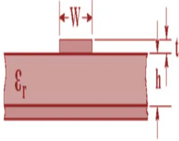
In general, the microstrip resonators have lower and upper conductive planes parted by a dielectric substrate with an insulating permittivity ε
r
and a height h along with a width w and a
thickness t thatis on the higher part of a dielectric
[image:5.612.347.525.394.534.2]substrateas in Figure 1 [20].
Figure 1 Microstrip Transmission Line
These microstrip BPFs are obtainable in numerous wireless systems that tolerates signals in a particular frequency spectrum and reject signals at other frequency spectrum .They can be constructed
exploiting one or more resonators,
electromagnetically joined to each other. A resonator is a factual element that collects magnetic and electric current distributions in a frequency-conditional mode. At mid band frequency, the electric and magnetic current circulations in the resonator are repeatedly stored.
A well-organized microstri[p BPF can be used to abandon harmonic bands and spurious signals as advantageous as viable for MIMO wireless
1,1 2*,1 1,1 *2,2
1 2ISSN: 1992-8645 www.jatit.org E-ISSN: 1817-3195
3690 systems. Thus, to extremely reject the image of the sent signal, very narrow band BPF is required [7].
6. DESIGN AND RESULTS
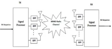
[image:6.612.325.521.86.277.2]Alamouti structure is adopted expansively in MIMO wireless systems in this study. The implemented block diagram of MIMO applies STBC active signal processors at the sending and receiving antennas as illustrated in Figure 2.
Figure 2 The adopted MIMO scheme
At this point, the carrying out and characteristic of microstrip BPF is described, that are used to reject harmonics or image bands within 2.4 GHz ISM band. To absolutely discard the lower hrmonic of the sent signal, narrow band BPF is required. Microwave office EM software package has been used in the design and simulation of that BPF. This simulator has schematic circuit and electromagnetic simulation tools that present high-quality performance in capacity, accuracy, speed and convergence. The BPF is designed from uniformed patch topologies to make available a high performance of BPF frequency response between the input and the output ports.
The designed BPF is clarified in Figure 3, and it was structured using a substrate with ε
r of 10.2 and h of 1.27 mm and loss tangent of 0.002. Dual 50 ohm feeders as input and output (I/O) ports are positioned in right and left sides of microstrip resonator. The proposed filter have size of 14 x 12 mm2 and a=1.2 mm, s=1mm, y=0.6mm, j=5.4 mm
[image:6.612.104.295.229.313.2]while c=0.8 mm, w=5 mm and r=9 mm.
Figure 3 Suggested narrow band microstrip filter
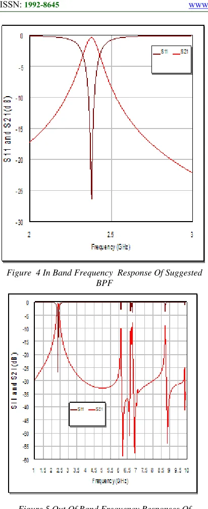
The consequential simulated responses of S11 and S21 responses are illustrated in Figure .4. At this point, passband has resonance frequency around 2.4 GHz with a bandwidth of 111.7 MHz, 26.4 dB return loss and 0.4 dB insertion loss, are feasibly detected. As compared with most filters described in [21, 22], the proposed filter has less insertion loss, better return loss and more miniature dimensions under similar substrate specifications and same or close to mid-band frequency as it is understood by Table 1. The new filter design has small size and good quality frequency responses along with obstructed higher harmonics (image bands) in out of band regions, which are much-desired characteristics for any MIMO wireless system as it can be observed from Figure 5.
Table 1 Designed BPF For MIMO Wireless Scheme In This Paper As Compared With [21] And [22] At Same
Dielectric Specifications
Parameters In this study
MLPF BPFs based on 0th, 1st, 2nd and 3rd iteration
reported in [21]
BPF reported
in [22] Mid-Band
Frequency (GHz)
2.4 2.4 2.43
Insertion Loss(dB),S
21
0.4 0.224,0.334,0.123,0.0176 0.02
Return Loss(dB),S
11
26.4 10,10,14,23.9 29
Overall dimension
(mm2)
10.6 x
9 16 16,13 13,10 10,7.97.9
[image:6.612.314.542.544.698.2]3691 Figure 4 In Band Frequency Response Of Suggested
BPF
Figure 5 Out Of Band Frequency Responses Of Suggested Filter
Insertion loss in the peak of S21 response at centre frequency in dB unit, is normally applied in communications schemes to determine the boundary attenuation which produces from a microstrip BPF inclusion into the signal path. In contrast, return loss stands for a determined voltage standing wave ratio or S11 magnitude at centre frequency dB unit also. It is related to the impedance change among the circuits. For higher than 1 GHz, the material specifications besides the connector or cable dimensions have an vital
[image:7.612.315.520.263.511.2]influence in the impedance matching or mismatch margins. A large value of return loss represents an upper quality of filter under test. In view of that, the insertion loss and return loss values of the projected filter are appropriate for IEEE802.11b MIMO wireless network. Fig.6 presents the phase response of S21 and S11 parameters for the designed microstrip filter. It response has fine linearity that indicate remarkable features in the filter design concept of quasi-elliptic response. Group delay within passband region is depicted in Fig.7. It exhibits reasonable delay time during filtering operation with magnitudes of several nanoseconds.
[image:7.612.322.511.463.675.2]Figure 6 Phase Response Of S21 And S11filter Responses
Figure 7 Group Delay Of S21 Filter Response In Nanoseconds
1 2 3 4 5 6
Frequency (GHz) 0
1 2 3 4
ISSN: 1992-8645 www.jatit.org E-ISSN: 1817-3195
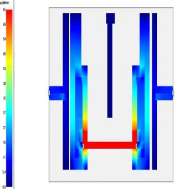
3692 Figures 8-11 exemplify the current arrangements of the simulated BPF at fundamental, 2nd harmonic 3rd
and 4th harmonic frequencies at 2.4, 4.8, 7.2 and
9.6 GHz respectively. All results are in Ampere/Meter units as simulated magnetic field intensity. These values are varied from red to blue colours as supreme and bottommost magnetic field intensities. It is distinct by these below figures that the simulated BPF is effectual and powerful only at fundamental frequency 2.4 GHz by highest current intensity of 65 Ampere/Meter as compared to 2nd,
3rd and 4th harmonic frequencies with utmost
current intensities of 7.2, 9.1 and 8.9 Ampere/Meter respectively that is manifest for impeding non- useful image bands at 2nd, 3rd and 4th harmonic
frequencies for wireless computer networks.
[image:8.612.308.534.38.269.2]Figure 8 Current Patterns Of The Simulated BPF At 2.4 Ghz
[image:8.612.93.268.290.477.2]Figure 9 Current Patterns Of The Simulated BPF At 2nd Harmonic Frequency Of 4.8 Ghz
[image:8.612.93.270.523.700.2]Figure 10 Current patterns of the simulated BPF at 3rd harmonic frequency of 7.2 GHz
Figure 11 Current Patterns Of The Simulated BPF At 4th Harmonic Frequency Of 9.6 Ghz
Through the influence of this filter, MATLAB routine steps for bit error rate determination using STBC scheme and phase shift keying (PSK) digital technique are:
1. Adjust the mid-band frequency of 2.4GHz using proper interface between Microwave Office simulator and MATLAB simulations and adjust the number of sent bits in MATLAB simulator.
2. Adjust number of transmit and receive antennas for the adopted MIMO system.
3693 is sent to the 1st time slot,
2
C
to the 2nd time slot, and so forth.4. Apply these sequences to STBC encoder.
5. Simulate PSK modulation techniques using these sequence
6. Evaluate transmission matrix, channel matrix and received signal for each receiving antenna.
7. Simulate QPSK demodulation techniques .
8. Apply the demodulated signals in STBC decoder
9. Computing the number of bit errors. 10. Organize all over again the related
[image:9.612.314.524.303.547.2]steps for various magnitudes of signal to noise ratio.
Table 2 The Adopted Channel Model Parameters
The parameters that are used in the channel model simulation are presented in Table 2. It is imperative at this point to reference that all simulated bit error ratio responses presented in this study have completed with similar sent bits of 10 bits and carrier frequency of 2.4 GHz.
A channel code has been used for data encoding, and the encoded data is riven into dissimilar data streams all sent using several sending antennas. The description of received signal at each receiving antenna is linear.
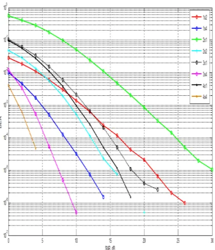
Figure 12 describes the bit error rate (BER) responses in accordance with signal to noise ratio
(S/N) for QPSK digital modulation over Rayleigh channel. It clarifies as transceiver antennas increase, the bit error rate stays on lessening and gives greater BER output attributable to spatial diversity.
It is imperative to point out that (M=1, N=2 and M=1, N=4) antenna arrangements have superior quality of BER responses as compared to (M=2, N=1 and M=4, N=1) antenna arrangements. This is attributable to the received information from the dynamic channel produces antenna diversity order of 4 and 8, where diversity order is two times the receive antennas number. For transmitted data of 1000000 bits, BER is feasibly measured under
[image:9.612.85.278.344.542.2]10 regularly. The most gainful BER is located in (4 x 4) transceiver arrangements.
Figure 12 Output BER Responses Of QPSK MIMO System With Various Antenna Configurations
7. CONCLUSIONS
In this research, new employment of miniature microstrip BPF is used to decline image bands. The projected filter gives upper harmonic repression in out of band region that is stimulating trait in MIMO communication systems. Also, it has obvious smaller insertion loss and higher return loss magnitudes than reported microstrip BPFs for wireless schemes indicated in [21, 22] as well as the compactness property for the proposed filter
Parameter Magnitudes
Carrier frequency 2.4 GHz
Sampling frequency 10 KHz
Transmitted bits 10 bit
Modulation and
demodulation type
QPSK
No. of transmit and
receive antennas
ISSN: 1992-8645 www.jatit.org E-ISSN: 1817-3195
3694 Incidentally, the proposed IEEE802.11b wireless model has linear phase response and very good group delay. Also, by interfacing the frequency details to MATLAB simulation of MIMO-STBC model, the system presents satisfactory bit error rate performance using QPSK digital modulation technique, as it offers a diversity gain through coding across space and time to achieve a reliable transmission.
ACKNOLEDGMENTS
The author thank Imam Kadhum University College and Islamic University College in Iraq for their support for this study.
REFERENCES:
[1] Y.S.Mezaal, “Performance Enhancement of IEEE 802.11 Wireless Network Using MIMO Technique”, Proceedings 2nd international conference of southern technical university, Basrah, Iraq, 2017.
[2] Hussein Ali Rasool, “Enhancement LTE-A Using MIMO Technology”, International Journal of Computer Science Engineering and Technology, Vol 4, No. 3, 68-73, 2014. [3] S. M. Alamouti , “A Simple Transmit Diversity
Technique For Wireless Communications”, IEEE Journal on Selected Areas in Communications, vol.16, pp. 1451- 1458, 1998.
[4]K . Kalliola, “Experimental Analysis of Multidimensional Radio Channels”, Ph.D. Thesis, Helsinki University of Technology Radio Laboratory Publications, 2002.
[5] A. H. Al-Hassan, “Design and Implementation of Software Radio Receiver Over Mobile Channel”, MSc. Thesis, Al-Nahrain University, 2004.
[6] S. H. Krishnamurthy, “Fundamental Limits and Joint Design of Wireless Systems with Vector Antennas”, Ph.D. Thesis, North Carolina State University, 2005.
[7] A. Wilzeck, M. El-Hadidy, Q. Cai, M. Amelingmeyer, and T. Kaiser, “MIMO Prototyping Testbed with off-the-shelf plug- in RF Hardware”, IEEE Workshop on Smart Antennas, Germany, 2006.
[8] D. Q. Trung, N. Prayongpun, and K. Raoof, “Antenna Selection for MIMO Systems in Correlated Channels with Diversity Technique”, 4th IEEE International Conference on Wireless Communication, Networking and Mobile Computing, China, 2008.
[9] A. Lozano and N. Jindal, “Transmit Diversity vs. Spatial Multiplexing in Modern MIMO Systems”, 186 IEEE Transactions on Wireless Communications, Vol. 9, No. 1, 2010.
[10] P. Bhatnagar, et.al, “Enhancement of OFDM System Performance with MIMO technique”, International Journal of Computer Technology and Electronics Engineering,Vol. 1, No. 3, 2011.
[11] Y.S. Mezaal, H.T. Eyyuboglu, J.K. Ali, “New microstrip bandpass filter designs based on stepped impedance Hilbert fractal resonators”, IETE Journal of Research,Vol. 60, No.3, 257-264, 2014.
[12] Y.S. Mezaal, J.K. Ali and H.T. Eyyuboglu, . “Miniaturised microstrip bandpass filters based on Moore fractal geometry", International Journal of Electronics, Vol.102, No.8, 1306-1319, 2015.
[13] Y.S. Mezaal, H.T. Eyyuboglu and J.K. Ali, “Wide Bandpass and Narrow Bandstop Microstrip Filters Based on Hilbert Fractal Geometry: Design and Simulation Results”, PLOS ONE |DOI:10.1371/journal.pone.0115412
[14] I. Lee, “Channel equalization technique for space time block codes in non quasi-static channels”, IEEE 60th Vehicular Technology Conference, 2004.
[15] Y. Huang, B. Pei, and H. Zhang, “System Performance Research and Analysis of MIMO-OFDM Based on Space Time Block Codes”, International Conference on Intelligent Control and Information Processing, pp 414-417, 2010.
[16] M. Jankiraman, “Space-Time Codes and MIMO Systems”, Artech House, Boston, London, 2004.
[17] E. Biglieri, R. Calderbank, A. Constantinides, A. Goldsmith, A. Paulraj, H. V. Poor, “MIMO Wireless Communications”, Cambridge University Press, USA, 2007.
[18]M. Rintamaki, “Adaptive Power Control in CDMA Cellular Communication Systems”, Helsinki University of Technology publisher, 2005.
[19] B. Vucetic, and J. Yuan, “Space-Time Coding”, John Wiley & Sons Ltd, 2003. [20] J. S. Hong, “Microstrip Filters for
3695 [21] N.N. Husain, “Performance Enhancement of
Bandpass Filters for Wireless Applications”, MSc. Thesis, University of Technology, Baghdad, 2008.