Lüke and power residue sequence
diffusers
Dadiotis, K, Angus, JAS and Cox, TJ
http://dx.doi.org/10.1121/1.2885761
Title
Lüke and power residue sequence diffusers
Authors
Dadiotis, K, Angus, JAS and Cox, TJ
Type
Article
URL
This version is available at: http://usir.salford.ac.uk/14626/
Published Date
2008
USIR is a digital collection of the research output of the University of Salford. Where copyright
permits, full text material held in the repository is made freely available online and can be read,
downloaded and copied for noncommercial private study or research purposes. Please check the
manuscript for any further copyright restrictions.
Lüke and power residue sequence diffusers
a)Konstantinos Dadiotis,b兲Jamie A. S. Angus, and Trevor J. Cox Acoustics Research Centre, University of Salford, Salford M5 4WT, United Kingdom
共Received 21 September 2007; revised 22 January 2008; accepted 4 February 2008兲
Conventional Schroeder diffusers have been successfully used for many years. However, their frequency range is limited by the flat plate effect that occurs when all the wells radiate in phase. This occurs at harmonics ofp times the design frequencyf0, wherep is the small prime that is used to
generate the structure. A typical diffuser, usingp= 7 andf0= 500 Hz, has an upper frequency limit
of only 3.5 kHz. Achieving a first flat plate frequency above 20 kHz requires a prime equal to at least 41 and results in diffusers that are too big to be practical in most applications. This paper suggests an alternative approach using number theoretic sequences that, although short in length, are based on large integers. Two new sequences, Type-II Lüke and power residue, have this desired characteristic. They are investigated using both simple models and the more exact boundary element method. The results show the flat plate effect is moved to much higher frequencies as expected. For Lüke sequences at certain frequencies, redirection rather than dispersion is achieved. Modulation techniques can be used to mitigate these problems. Power residue sequences perform the best, providing good diffusion and a flat plate frequency outside the audible range.
©2008 Acoustical Society of America. 关DOI: 10.1121/1.2885761兴
PACS number共s兲: 43.55.Br 关NX兴 Pages: 2035–2042
I. INTRODUCTION
In the 1970s, Schroeder introduced the concept of using maximum length sequences in diffuser design to improve sound diffusion in concert halls and reverberation chambers.1 Since then, a variety of diffusers has been developed.2A well known and widely applied class of diffusers is one that con-sists of wells with the depths being determined by an integer-based pseudorandom sequence. The most common examples are quadratic residue diffusers共QRDs兲or primitive root dif-fusers 共PRDs兲.2,3 A cross-section through such a device is shown in Fig.1共a兲.
When sound is incident on this surface, the wave has to travel different distances before it is reflected back out of each well. Thus the reflected waves display different phases as they exit the wells. By choosing well depths which result in appropriate radiated phases, scattering via interference be-tween these reflected waves is achieved.
The depth of thenth welldnin the diffuser is set using a
pseudorandom sequence:2
dn= sn0
2P , 共1兲
wheresnis thenth term of the pseudorandom sequence,0is
the design wavelength, andPis the integer the sequence has generated using, e.g., the primep for QRDs.
Unfortunately, at certain specific frequencies, the wells of these diffusers radiate in phase and the whole structure will reflect sound as though it is a flat surface. This flat plate effect arises because there is a simple integer relationship
between the different well depths. To illustrate this, consider aN= 7 QRD which is based on the sequence关0,1,4,2,2,4,1兴. Because of this construction, there will be a frequency for which the wells corresponding to 1 in the sequence will equal half a wavelength. At this frequency, all the reflected waves radiated from the diffuser wells will be in phase, due to their integer relationship. The lowest frequency that this flat plate effect is noticed is usually Pf0, where f0 is the design frequency.2 The flat plate effect is also seen at har-monics of this lowest frequency. Unfortunately, for both the QRD and PRD, the prime number is directly linked with the period of the sequence and therefore the number of wells in the diffuser N. For the QRD P=N while for the PRD
P=N+ 1. One solution is to move the first flat plate fre-quency to a high enough frefre-quency so that it is not of con-cern. For QRDs and PRDs, however, in order to move the flat plate effect to higher frequencies, one is forced to use much longer sequences, which results in wider diffusers. The experience of the last 30 years shows that short period dif-fusers are used much more often than wide difdif-fusers, not least because such surfaces are cheaper to make and install. Angus suggested the use of non-integer based sequences to remove this problem,4but the physical realization of the diffusers suggested is problematic. Angus also suggested ways of mitigating the problem using orthogonal modulation schemes.5Another solution to this problem is to use numeri-cal optimization where a computer searches for the best well depths.6Because the computer no longer uses depths that are integer based, then the flat plate effect is not a problem. However, the optimization process is a rather brute-force de-sign method, and consequently, a more elegant solution based on number theory was sought.
It is suggested that by utilizing integer-based sequences that have small periods, but are generated using larger
inte-a兲
Portions of this work were presented in “Lüke and Power Residue Se-quence Diffusers,” Proceedings of International Conference of Acoustics, Madrid, Spain, September 2007.
b兲Author to whom correspondence should be addressed. Electronic mail:
gers, the flat plate effect can be avoided. Two possible se-quences are investigated: Type-II Lüke and power residue. The paper begins by outlining the Fourier prediction model used as it enables the underlying principles to be more easily understood. Then the general principles behind the sequences are given and their performance considered using this model. Finally, a boundary element model 共BEM兲 is used to gain more accurate predictions.
II. THEORY
Consider a structure with a distribution of reflection co-efficientsRnacross its surface. The structure is considered to
be extruded in one direction, so that significant diffraction only occurs in one plane. This simplifies the prediction and interpretation of the results. For normal incidence sound, the far field reflected pressure, p, can be found using2
p共兲=
兺
n=0 N−1
Rne−inkdnsin共兲, 共2兲
whereis the angle of reflection,nis the well number,Rnis
the reflection coefficient of thenth well, kthe wavenumber andNthe number of wells. Note that this is a discrete Fou-rier transform usingkd sin共兲, and for this reason the predic-tion model is often referred to as a Fourier model.
III. SEQUENCES
The goal of a diffuser design is usually a uniform scat-tered pressure distribution, and therefore a structure that has reflection coefficients whose Fourier transform has a uniform magnitude should diffuse well. The Wiener–Khinchin theo-rem states that the square of the magnitude of the sequence’s Fourier transform is equal to the Fourier transform of its autocovariance 共or autocorrelation兲 function. As a result a sequence of reflection coefficients, whose autocorrelation function is a Kronecker delta function, will display good diffusion properties. Consequently, pseudo-random number sequences should be a good choice, because they display this ideal property, and many have been devised for use in other areas of engineering and science.
The reflection coefficients of the wells are given by
Rn共f兲= exp
冋
i2 sn P f f0册
, 共3兲
wheref is the frequency andf0is the design frequency of the
diffuser.
For some frequencies, all the phases of the reflection coefficients will become multiples of 2, and so all the re-flection coefficients will be 1. This occurs when the fraction
f/共Pf0兲 is an integer. These flat plate frequencies, as shown
in Fig.1共b兲, are given by
fm=mPf0, wherem= 1,2,3. . . 共4兲
While in theory every structure displays an infinite num-ber of flat plate frequencies, in reality it is rare for there to be more than one of these frequencies in the bandwidth of con-cern. Therefore, it is common to refer to the first of them as “the” flat plate frequency.
Of interest in this paper are power residue and Type-II Lüke sequences, which are both manipulations of primitive root sequences.
A. Type-II Lüke sequences
Type-II Lüke sequences are generated in families which have p− 1 members, each of which could be used to make a diffuser. For any given prime p the nth terms of the se-quences are given by7,8
sn共 r兲
=共␣n共p− 1兲+rnp兲modp共p− 1兲, 共5兲 where␣ is the primitive root of the prime p,r denotes the family member and mod indicates the least non-negative re-mainder. The sequences are generated via the integer P
=p共p− 1兲 and have a period length ofN=p− 1. A necessary condition is 0艋n,r艋p− 2.
The reflection coefficients of Type-II Lüke sequences have the following, two valued, autocorrelation magnitudes:
兩Gr,r共兲兩=
冦
p− 1, = 0
1, −p− 1 2 艋艋
p− 1
2 ⫽0,
冧
共6兲
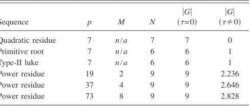
[image:3.612.318.557.37.176.2]where G is the autocorrelation and is the autocorrelation delay variable. This autocorrelation function is the same as that of a PRD of the same period. Note that it is the autocor-relation magnitude that is constant for 兩兩⬎0, which is un-usual for sequences used in diffuser design. Table I shows the properties for an example sequence based p= 7.
TABLE I. Characteristics of the autocorrelation function for some cases of Type-II Lüke and power residue sequences.
Sequence p M N
兩G兩
共= 0兲
兩G兩
共⫽0兲
Quadratic residue 7 n/a 7 7 0
Primitive root 7 n/a 6 6 1
Type-II luke 7 n/a 6 6 1
Power residue 19 2 9 9 2.236
Power residue 37 4 9 9 2.646
[image:3.612.316.561.634.738.2]Power residue 73 8 9 9 2.828
FIG. 1. 共a兲One period of a quadratic residue diffuser共QRD兲of well width
w and depth of thenth well, dn.共b兲The flat plate effect occurs when a
multiple of/2 exactly fits in all the wells.
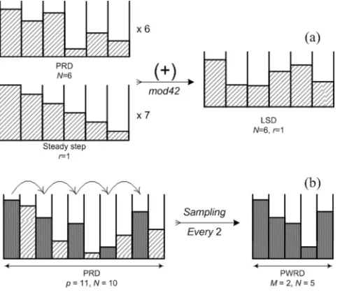
Essentially the Type-II Lüke sequences are formed by superposing the primitive root sequenceq of prime p:
qn=anmodp 共7兲
and a steady step sequencet of the same period:
tn=rnmodp− 1 共8兲
withrgiving the step size, as shown in Fig.2.
This is possible because a linear ramp can be added to any number sequence, provided the period is correct, without changing the autocorrelation properties.8
For the above reason, every primitive root sequence can be considered to be the first sequence共r= 0兲of each Type-II Lüke sequence family. From any primitive root sequence a set of p− 2 new Type-II Lüke sequences can be generated, each one with a different step size.
To give an example forp= 7,␣= 3 andr= 0 the primitive root sequence isq=关1 , 3 , 2 , 6 , 4 , 5兴. The phases of the reflec-tion coefficients of this sequence, at the design frequency f0,
are 2/7 23/7, 22/7, etc. The flat plate effect will occur when all phases are multiples of 2; this can be accom-plished by multiplying all the arguments by a factor of 7, which happens when the incident wave is of frequency
f= 7f0as previously discussed.
On the other hand for p= 7, ␣= 3 and r= 1 the Type-II Lüke sequence is given by s=关6 , 25, 26, 15, 10, 23兴. The phases of the reflection coefficients in this case, at the design frequency f0, are 26/42, 225/42, etc. For all the phases in this case to become multiples of 2they need to be mul-tiplied by a factor 42 which happens when the incident wave is of frequency f= 42f0. Therefore, by using Type-II Lüke sequences it is possible to increase the frequency at which all the wells radiate in phase by a factor of 6.
B. Power residue sequence
For a prime numberpthat can be expressed in the form:
p=MN+ 1, 共9兲
whereM andNare integers, M power residue sequences of periodN can be generated using the equation8
sn共 r兲
=共␣rn兲modp, 共10兲
where 0艋r⬍M, 0艋n⬍N,␣is a primitive root ofp and is␣ raised to the power ofM 共=␣M兲.
In the case that a set ofNintegersD=关d1,d2, . . .dN兴are
modulo an integerp they are said to form an integer differ-ence set if every integerh⫽0 can be expressed in exactly ways in the form:
di−dj⬅hmodp 共11兲
The properties of the difference set are usually repre-sented using the nomenclature 共p,N,兲.
If, and only if, the power residue sequence forms a cy-clic difference set 共p,N,兲, then the reflection coefficients that it generates displays two level autocorrelation magnitudes:8
兩Gr,r共兲兩=
冦
N, = 0
冑
N− NM+
1
M,
N− 1
2 艋艋
N− 1
2
冧
,共⫽0兲, 共12兲
where Table Igives a few examples, and demonstrates that power residue sequences display worse autocorrelation prop-erties than QRD, PRD and Type-II Lüke sequences, as the out-of-phase magnitude is always greater than 1 and be-comes greater as M increases.
Essentially, power residue sequences are under-sampled primitive root sequences, with a sample taken every Mth coefficient, with a different starting point, as shown in Fig.
2共b兲.
The starting point is set by r. For instance, for p= 11, the primitive root is 2, and the primitive root sequence is
q=关1 , 2 , 4 , 8 , 5 , 10, 9 , 7 , 3 , 6兴. For M= 2, and r= 0 every other coefficient is taken to form the power residue sequence starting from the first s共0兲=关1 , 4 , 5 , 9 , 3兴 while for r= 1 the
starting point is the seconds共1兲=关2 , 8 , 10, 7 , 6兴. Note that the
one sequence is the inverse of the other. If the coefficients of
s共1兲 are cyclically shifted back 2 positions, it becomes
关10,7,6,2,8兴. So in this case, the two power residue sequences are connected via the equation
s共0兲=p−s共1兲. 共13兲
This connection between the two sequences results in pairs of diffusers in a family that performs similarly, because pairs have reflection coefficients with opposite phases.
[image:4.612.54.297.36.244.2]To postpone the flat plate effect to a higher frequency, sequences with larger p are needed. There are three cases that form cyclic difference sets and need to be considered:8 FIG. 2. Schematic showing the generation of共a兲Lüke共p= 7 ,r= 1兲and共b兲
M= 2 andNodd
M= 4 andN=j2wherejis odd
M= 8 andp= 8j2+ 1 = 62m2+ 9
wherejandmare odd 共14兲
Since the goal is to push the flat plate effect to higher frequencies, the most promising case is the last as it com-bines higher primes p with the shortest sequences possible. The first case that falls under this category is
M= 8, n= 3, m= 1⇒p= 73.
This generates a short sequence typical of the length used in practical Schroeder diffusers共periodN= 9兲but with a prime number generator of 73. One such a sequence is
s共1兲=关5 , 10, 20, 40, 7 , 14, 28, 56, 39兴, which is the second of
the family共r= 1兲. The higher prime number gives a first flat plate frequency of 73 times the design frequency.
IV. SCHROEDER DIFFUSERS
In order to evaluate the performances of the two new sequences, diffusers were simulated and predictions of their scattered pressure distribution were made. From these their diffusion coefficient2 was calculated and comparisons with other integer based diffusers such as the standard QRD and PRD were made.
As the main reason for choosing these new sequences was the fact that they are both based on large prime number generators and display two level autocorrelation properties, according to a Fourier model, this model will initially be used to estimate their relative performance.
A. Type-II Lüke diffusers
Type-II Lüke sequences are formed by the addition of a step sequence to a primitive root sequence. Consequently, diffusers that are generated with steady step sequences of opposing inclinations can be paired as they perform simi-larly. This leaves one sequence that cannot be paired, the middle one which is generated forr=M/2.
The case of Type-II Lüke sequence diffusers共LSD兲 gen-erated by the integerP= 42 is considered. These are diffusers of periodN= 6 and well width approximately 4.2 cm. Their design frequency is f0= 500 Hz. Eight periods of the diffuser
are used. This gives a structure with an overall width of 2 m. The diffusion coefficient will be used initially to esti-mate the overall performance of the diffusers. This coeffi-cient has values from 0 to 1, where 0 represents perfect specular reflection 共no diffusion兲 and 1 represents uniform scattered distribution into all angles of reflection9共complete diffusion兲.
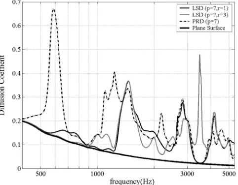
Figure3displays the diffusion coefficients of some dif-fusers of this family of LSDs along with the equivalent PRD of the same characteristics. Since the design frequency used is 500 Hz the PRD is expected to display a flat plate effect at 7500 Hz= 3.5 kHz while the LSDs are expected to display their first flat plate effect at 42⫻500 Hz= 21 kHz.
Unfortunately the LSD with r= 1 displays a dip in the diffusion coefficient similar to the PRD’s flat plate effect at 3.5 kHz. This is because the r= 1 LSD causes redirection rather than diffusion at this frequency. The reflection coeffi-cients at 3.5 kHz have phases of 0, /3, 2/3, , 4/3, 5/3 which have equal phase shift increment of /3 from one well to the next. This constant phase increment of the reflection coefficients is why the main reflected lobe is redi-rected into another direction; it is identical to the phase shifts used to beam steer loudspeaker arrays. This behavior is in-herent in Lüke sequence diffusers because they are formed by adding a PRD to a linear stepped ramp. At the frequency in question, all the reflection coefficients of the base PRD are equal to 1 with a phase shift of 0, leaving only the linear stepped ramp. Essentially the PRD disappears and the dif-fuser acts like a tilted flat plate.
This can be seen in Fig.4 where the scattered intensity distribution from one period of this LSD withr= 1 is com-pared to that from a plane surface of the same size and shows that the diffuser is redirecting instead of scattering the inci-dent wave.
[image:5.612.318.559.36.224.2]All the LSDs of the family display this behavior with the exception of the middle one共in this caser= 3兲 共Fig.3兲which appears to be dispersing the incident wave uniformly. How-FIG. 3. Autocorrelation diffusion coefficient, as predicted using the Fourier model, of different types of periodic Lüke and primitive root diffusers of the same total width.
FIG. 4. Scattered intensity distribution共dB兲at the tilted flat plate frequency of a Lüke diffuser.
[image:5.612.317.557.590.713.2]ever, a closer inspection reveals that the reflection coeffi-cients at this frequency are simply +1 and −1 one after the other共representing a steady phase shift of兲. Based on the Fourier model, cancellation in the specular reflection direc-tion occurs. However, mutual interacdirec-tions between adjacent wells will tend to “smooth out” the surface pressure distri-bution and reduce the cancellation in real surfaces.
All sequences of the same family perform almost iden-tically when considered in a 1/3rd octave band. They vary in their performance at specific frequencies and in the overall variation of their diffusion coefficient with frequency. The diffusers that have r= 2 and r= 4 display more variation of diffusion with frequency and have many dips in the diffusion coefficient. For this reason they are considered to perform worse than r= 1,r= 3, and r= 5. However, it remains to be verified whether the r= 3 LSD will perform as well as pre-dicted by the Fourier model.
Another aspect worth taking into consideration is the maximum depth of the diffusers because of the space it re-moves from the room. For this family of LSDsr= 1 displays the smallest maximum depth of 21.3 cm which is consider-ably smaller than that of the equivalent PRD which is 29.5 cm, for the given design frequency. However, although LSD共r= 1兲appears to be the most promising of its family it does not seem to perform any better than the equivalent PRD.
The dips that are evident in the diffusion coefficients of all three structures around 1.2 and 2.4 kHz are due to the periodicity caused by the repetition of the base diffuser 8 time. Because of this, the structures can be considered as 8 point sources spaced 25 cm apart which will generate addi-tional minima due to the grating lobes generated by that periodicity.
B. Power residue diffusers
Power residue diffusers 共PWRDs兲 of the same family can be separated into pairs that diffuse similarly as well. Each diffuser is paired with its inverse, which is found in the same familyM/2 sequences away共兩r1−r2兩=M/2兲.
The cases of PWRD of periodN= 9 are taken into con-sideration. They can be generated by the following cases:
M= 2,N= 9⇒p= 19
M= 4,N= 9⇒p= 37
M= 5,N= 9⇒p= 73
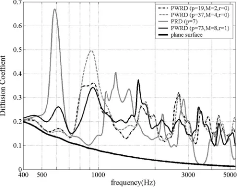
Their well width was set to approximately 4.4 cm so that a structure of 5 periods was 2 m long and their design frequency was also set to 500 Hz. This allows direct com-parison of their diffusion performance with the Lüke se-quence diffusers. Given their design frequency and their prime number generator their flat plate frequencies are ex-pected to be 8.5, 18.5 and 37.5 kHz, respectively.
Figure 5 shows the performance of one case of each PWRD family compared to 8 periods of a PRD共p= 7兲. Their flat plate frequency is, as expected, far beyond the frequency range of the PRD, and that of the graph. However, they seem to perform worse than the PRD at some frequencies. How-ever, they display a more uniform performance over the whole frequency range. Again the diffusers all display poor performance at just over 700 Hz due to the repetition of a single diffuser.
These three diffusers were chosen over others of their family because they performed better. Both PWRD共p= 19兲 performed identically on their own, as one is the inverse of the other. The other two PWRDs were chosen because they appeared to perform better, or as well as, the rest of the diffusers in their family. Overall, the most promising are the diffusers of larger integer number共p= 37 andp= 73兲as they display more uniform diffusion over the bandwidth. Further-more, the fact that there are more than two diffusers in these families allows more design options. The shallowest diffuser is the PWRD based on the prime p= 73 which displays a maximum depth of 26.4 cm. The other cases have maximum depths around 30 cm.
C. Boundary element method„BEM…
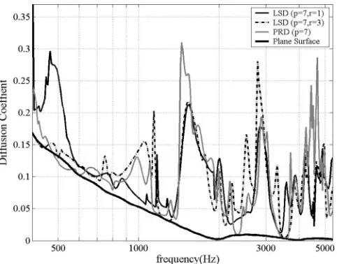
Having predicted the performance of the diffusers using the Fourier method, and established their overall behavior, a more detailed and exact BEM10simulation was used for pre-diction as it has been shown to give accurate results for Schroeder diffusers.11The design frequency and dimensions of the diffusers are the same as given previously and the results are displayed in Figs. 6 and 7. The diffusion coeffi-cients display a broadly similar pattern to those of the Fou-rier model but they seem to have more variation with fre-quency.
[image:6.612.317.558.36.225.2]graph that the middle diffuser of the family共r= 3兲performs almost identically to the PRD at the flat plate frequency of the latter. This contradicts the earlier prediction of good dif-fusion from the Fourier model 共Fig.3兲. On the other hand, the initial prediction of the behavior of the other LSD
共r= 1兲 is quite accurate. It is also evident that none of the LSDs perform any better than the PRD.
Figure 7 shows the behavior of PWRD of period N= 9 with the same characteristics that were used for the Fourier model in comparison with the PRD of periodN= 6 in 1/3rd octave bands. Once again, the results display a similar pat-tern to that of the Fourier model. Unlike the LSDs the PWRDs have no problematic frequencies within this band-width in particular p= 73 has; better diffusion than all the other ones.
V. MODULATION AND PERIODICITY
To cover large surface areas more than one period of a diffuser structure is commonly used. The repetition of the sequences introduces the problem of periodicity. Periodicity causes harmonics to be created in the autocorrelation func-tion this; creates sharper grating lobes and as a result a less uniform scattering distribution.5,12
One method of dealing with the effects of periodicity is to modulate the base sequence with another.5,12 In order to modulate two sequences a binary pseudorandom sequence is required. The binary sequence defines the order in which the sequences will be placed with 1 corresponding to the first sequence and 0 to the second.
There are three major ways of choosing the second se-quence to be used in the modulation. These are as follows:
共1兲 Using the inverse of the base sequence: An inverse sequence is created by subtracting the original sequence from the integer that it was generated from. So, for ex-ample, the sequence that will generate the inverse dif-fuser of the LSD withP= 42 andr= 1关6,25,26,15,10,23兴 is calculated by subtracting this sequence’s coefficients from its integer number generator, 42 in this case, to give
关36,17,16,27,32,19兴as the inverse.
共2兲 Using the base sequence in reverse order: Another technique for modulation is to use the same sequence but in reverse order. In practice this is easily achieved by rotating the diffuser in its plane such that its left becomes its right.13The modulation is essentially a diffuser and its mirror image. For example, for LSD with P= 42 and
r= 1 关6,25,26,15,10,23兴 the mirror diffuser is simply
关23,10,15,26,25,6兴. This method has the added advantage of the overall structure having the same depth as the base diffuser; in addition it only requires one base diffuser. However, it only works if there is a degree of asymmetry in the base diffuser.
共3兲 Using a different sequence to that of the base dif-fuser: In principle any alternate sequence may be used, but it is usual to use one that is performing better than the base sequence at the frequencies where it is perform-ing badly. For example, for the base sequence above, a suitable sequence would be P= 42 and r= 5
关6,11,40,15,38,37 because it complements the base se-quence in performance.
A. Type-II Lüke diffusers
[image:7.612.54.295.33.222.2]As shown above, at some frequencies the LSDs simply redirect the sound because they act like beam steerers. In general, diffusers should be dispersing sound and not simply redirecting it. An effective solution is to modulate the dif-fuser with another that, at the problematic frequencies, redi-rects sounds into another angle. Such a diffuser could be the inverse or the mirror image of the first diffuser or an LSD from the same family constructed from a step sequence of opposing inclination. Figure8displays the scattered distribu-tion from such composite structures at this frequency. The main lobe of the periodic diffuser has been substituted by FIG. 6. Autocorrelation diffusion coefficient, as predicted using the
bound-ary element model, of different types of periodic Lüke and primitive root diffusers of the same total width.
FIG. 7. One-third octave band autocorrelation diffusion coefficient, as pre-dicted using the boundary element model, of different types of periodic power residue and primitive root diffusers of the same total width.
[image:7.612.53.296.508.699.2]two wider lobes of less energy. Thus the incident wave is scattered more uniformly in comparison to the periodic dif-fuser.
The binary sequence关1,0,0,1,1,0,1,0兴was used to modu-late the base diffuser, LSD共r= 1,P= 42兲, in the three differ-ent ways discussed earlier. Modulation in all three ways im-proves the overall performance of the diffuser, as shown in Fig.9, because the diffusion coefficient is higher for all fre-quencies compared to the periodic case.
It is important to note that for the periodic case and the modulation with the mirror diffuser the maximum depth is 21.3 cm while for the inverse it is 29.5 cm and for the LSD of opposing inclination共r= 5兲it is 32.7 cm. From these three modulations the one with the inverse diffuser and the other with the LSD 共r= 5兲 seem to disperse best. However, if the maximum depth is taken into account, the fact that the modu-lated with the mirror diffuser will take up less space from the volume of the room could make it more desirable for some applications. If the lost volume is of no concern, it is impor-tant to note that the modulation with the other LSD manages to treat the notable dip of the diffusion coefficient that is evident in the other cases around 2.4 kHz.
The phenomenon of periodicity could be used to treat the problem of beam steering occurring with the LSD.
Con-sider a structure that is composed of the periodic repetition of LSDs. If the maximum reflection lobe could be set on the angle that a minimum of the periodicity pattern occurs, it could be cancelled out. Unfortunately, in order for that to be accomplished a large number of periods must be considered while the wells must be thinned down to unrealistic values. Even in the cases that uniform diffusion in achieved at the flat plate frequencies, the performance of the diffuser is worse than poor for the frequencies up to that.
B. Power residue diffusers
PWRDs do not present any notable problems until their flat plate frequency. So the only problem that needs dealing with is periodicity. The widely used modulation with the diffusers inverse can be applied in this case. The modulations with the mirror diffuser and another diffuser of the same family can be used as well. The binary sequence关1,0,1,1,0兴 has been used for the modulation.
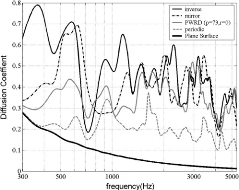
Figure10shows the diffusion coefficient of a PWRD of period N= 9, prime number generator p= 73 and r= 1. All modulations diffuse much better than the periodic case, in addition modulation with the inverse diffuser performs more uniformly compared to the others.
VI. DISCUSSION
This paper has presented two new types of diffusers, estimated their performance, and showed improved perfor-mance compared to a standard PRD. But which is the best sequence, Type-II Lüke or power residue?
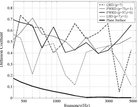
[image:8.612.53.294.31.155.2]The PWRDs seem to be the best. As Fig.11shows, both PWRDs in their modulated version have better diffusion co-efficients than the other diffusers. They have no problematic frequencies, where they are unable to scatter the incident wave, and they have a more uniform diffusion coefficient over this bandwidth. The PWRD generated when p= 73 could be preferable as it displays steadier diffusion with fre-quency.
FIG. 8. Scattered intensity distribution共dB兲at the flat plate frequency for two periods of LSD共p= 7 ,r= 1兲periodic and modulated with its inverse in comparison with a plane surface of the same width.
FIG. 9. Autocorrelation diffusion coefficient, as predicted using the Fourier model, of different modulations of Lüke diffusers of the same total width.
[image:8.612.316.557.36.228.2] [image:8.612.54.296.520.708.2]The LSD, shown in the above figure, is more ambigu-ous. It is evident that they do not diffuse as well as the QRD and the PRD except at their flat plate frequencies共3.5 kHz兲. The periodic version of the LSDs has a tilted flat plate at that frequency, but when modulated manages to avoid the prob-lem. Modulated the LSD is preferred to a PRD or QRD because it is well behaved until the flat plate frequency at 21 kHz.
VII. CONCLUSIONS
This paper has proposed the use of Type-II Lüke and power residue sequences for the design of number theoretic diffusers with a small numbers of wells per period. The logi-cal and mathematilogi-cal background has been presented and their performance has been predicted with both the Fourier and the boundary element methods. Classic Schroeder diffus-ers based on quadratic residue and primitive root sequences suffer from flat plate frequencies where no scattering is achieved. Type-II Lüke and power residue sequences use
larger numbers to generate the sequence, and consequently their flat plate frequencies are at much higher frequencies, often outside the audible range for practical diffusers.
The results show that Type-II Lüke sequences act like beam steerers at some frequencies, and consequently at these frequencies diffusion is poor. Modulation techniques have been presented to mitigate this problem. However, the per-formance of Power Residue sequences has been found to meet the initial demands for more-uniform diffusion and very high flat plate frequency and with the addition of modu-lation their performance is greatly improved.
Finally both types of diffuser are shown to display better diffusion characteristics when modulated than standard modulated quadratic and power residue diffusers.
1M. R. Schroeder, “Diffuse sound reflection by maximum-length
se-quences,” J. Acoust. Soc. Am.57, 149–150共1975兲.
2T. J. Cox and P. D’Antonio,Acoustic Absorbers and Diffusers: Theory,
Design and Application共Spon, 2004兲.
3T. J. Cox and P. D’Antonio, “Acoustic phase grating for reduced specular
reflection,” Appl. Acoust.60, 167–186共2000兲.
4J. A. S. Angus, “Non-integer-based diffusers,” Audio Engineering Society
107th Convention共1999兲.
5J. A. S. Angus and C. I. McManmon, “Orthogonal sequence modulated
phase reflection grating for wideband diffusion,” J. Audio Eng. Soc.46, 1109–1118共1998兲.
6T. J. Cox, “The optimization of profiled diffusers,” J. Acoust. Soc. Am.97,
2928–2936共1995兲.
7H. D. Lüke, “Families of polyphase sequences with near-optimal
two-valued auto- and crosscorrelation functions,” Electron. Lett. 28, 1–2
共1992兲.
8P. Fan and M. Darnell,Sequence Design for Communications Applications
共Wiley, New York, 1996兲.
9AES-4id-2001, “AES information document for room acoustics and sound
reinforcement systems-characterization and measurment of surface scatter-ing uniformity,” J. Acoust. Soc. Am.49, 149–165共2001兲.
10T. Terai, “On the calculation of the fields around three-dimensional objects
by integral equation methods,” J. Acoust. Soc. Am.68, 71–100共1980兲.
11T. J. Cox, “Predicting the scattering from reflectors and diffusers using
two-dimensional boundary element methods,” J. Acoust. Soc. Am. 96, 874–877共1994兲.
12J. A. S. Angus, “Using grating modulation to achieve wideband large area
diffusers,” Appl. Acoust.60, 143–165共1999兲.
13P. D’Antonio and T. J. Cox, “Aperiodic tiling of diffusers using a single
[image:9.612.54.295.34.221.2]asymmetric base shape,”18th ICAKyoto, Japan共2004兲. FIG. 11. One-third octave band autocorrelation diffusion coefficient, as
pre-dicted using the BEM, of different types of modulated diffusers of the same total width.