Effects of Nozzle Diameter on the Spray Characteristics of Premix
Injector in Burner System
SHAHRIN Hisham Amirnordin
a, SALWANI Ismail, RONNY Yii Shi Chin,
NORANI Mansor, MAS Fawzi, AMIR Khalid
bCombustion Research Group (ARG), Center for Energy and Industrial Environment Studies (CEIES), Universiti Tun Hussein Onn Malaysia, 86400 Parit Raja, Batu Pahat, Johor, Malaysia.
a[email protected], b[email protected]
Keywords: Nozzle diameter, premix injector, Eulerian multiphase flow, burner.
Abstract. An essential component of the injector nozzle geometry is to see the results spray atomization and mixture formation of the fuel-air combustion to improve performance, and reduce pollution from a burner. Studies involving the injectors in the combustion burner are still in a small proportion, particularly in the premix injector type. Thus, this study involves the efforts to determine the appropriate diameter of the premix injector where the injector sprays characteristics is produced by using Computational Fluid Dynamics (CFD). Multiphase of the volume of fluid (VOF) cavitations flow in the nozzle is determined through steady simulation while Eulerian-Eulerian two-fluid approach is used for performing mixing of Jatropha oil and air. Further simulation is conducted using a spray with a discrete phase injection at the outflow hole injector nozzle. The investigation involves the modification of nozzle geometry on three different sizes of 0.8mm, 1.0mm and 1.5mm with the analysis focused on nozzle flow characteristics of the injector. The results indicate that a small changes in injector gives high impact to the spray and combustion of a burner. This shows the importance of nozzle dimensions which influences the nozzle flow and affects the spray characteristics, hence influence the combustion and emission of the burner system.
Introduction
Burner is a heating device which is using an injectorto deliver fuel into the desired burning area. In this system, the fuel is atomized into a fine spray by using a pump forcing it through a nozzle of the injector. Premix injector is a type of indirect injection in which the fuel is injected into a sub-chamber to swirl the compressed air before deliver the spray into the area for combustion to occur. Many researchers had suggested the factors which affect the combustion and emission of the burner. Fuel physical and chemical properties [1],spray characteristics [2] and fuel-air mixing [3][4] were found to play an important role on the performance of the burner.
To encourage maximum combustion efficiency and minimize the emission of harmful gases, one injector should deliver fuel spray quickly spread and evaporate to produce a homogeneous mixture of fuel gas and air. Mode of spread droplet burning to encourage the formation of soot and nitrogen oxide (NOx) emissions is high and carbon monoxide (CO) should be avoided. From a practical standpoint, the fuel injector should produce good atomization of the fuel mass flow rate and a low pressure drop. Jet fuel spray or split in different regimes depending on the influence and interaction of the kinetic energy of the liquid, surface tension, viscosity, and the surrounding air [5].
Spray characteristics can be influenced by the parameters of seat angle, streamwise velocity or tangential velocity and nozzle exit diameter. Fuel properties such as viscosity, density and surface
tension also affect spray atomization [6]. Studies conducted by Yang et al. [7] show that the
atomization behavior are affected by the nozzle diameter. This contributes to the spray characteristics of the injectors. Two criteria were compared here: spray angle and cone shape.
The present study aims to investigate the characteristics of the premixed injector using Computational Fluid Dynamics (CFD).The premixed injector with eight holes is used at three different nozzle diameters on the injection angle of 45° [5] which produces proper burning of the system. ANSYS Fluent is used to simulate and determine the results in terms of penetration, spray cone angle, droplet density and Sauter mean diameter (SMD).
The rest of this paper presents the physical domain, boundary conditions of the simulation work and meshing scheme used.The next section consists of the results and analysis starting with grid independence study, flow analysis and spray characteristics of the injectors. Finally, the findings are concluded in the last section of this paper.
Methodology
[image:2.595.244.541.410.581.2]This study involved 3-dimensional, steady and multiphase simulation using Eulerian volume of fluid model for a mixture flow inside the injector as shown in Fig. 1. The mixture used was crude Jatropha oil (CJO) and air with the second stage of the simulation employed discrete spray model. Fig. 2 shows the computational domain which was obtained from the nozzle of premix injector.The premix injector has eight cylindrical holes with diameter of 0.8, 1.0 and 1.5 mm at an included
angle of 45o which was obtained from the previous experimental work [5].
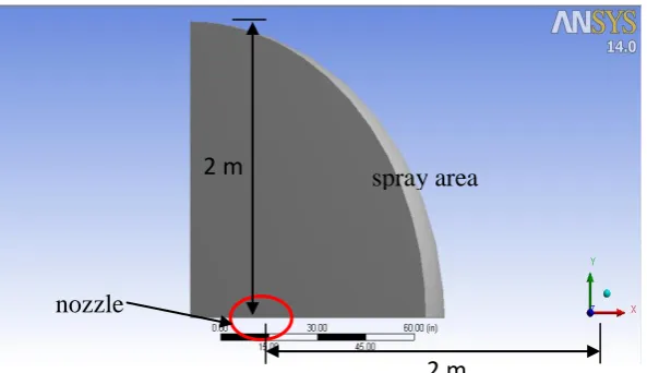
[image:2.595.95.198.413.555.2]To simulate the experiments, a single spray is considered by taking 1/8 part of the whole injector. The inlet was specified using mass flow rate, the solid wall, periodic wall and pressure outlet. The outlet was set at 2 m from the inlet to avoid backflow of the spray. Ambient temperature was set at 300K at the inlet and confining wallswhile the discretized domain is shown in Fig. 3 and 4. Unstructured grid with triangular cells was implemented with fine mesh was located at the inlet and outlet of the nozzle.
Figure 1: Model of premix injector showing the flow of fuel and air
Figure 2: Geometry of computational domain for premix injector and spray chamber
Figure 3: Grid generation of computational domain
Figure 4: Grid generation showing the critical area of nozzle and spray chamber
spray area
nozzle
2 m
2 m
[image:2.595.298.523.639.753.2]Results and Discussion
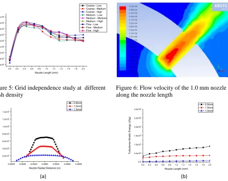
Grid sensitivity tests were conducted on the domain with different mesh size as shown in the Fig. 5. The calculation achieves the grid independence result between 24997 to 114555 with mean deviation ranges from 3.98 to 5.96 %. Small deviation of velocity shows the reliability of the meshing scheme to be employed further. Preferred mesh density is selected by obtaining the best fit of calculated velocity which is occurred at 26,015 number of elements.
Three different geometry are compared which consist of 0.8, 1.0 and 1.5 mm diameter of injector nozzle. In all three cases, the liquid and the gas phase boundary conditions are kept constant. All the vapour properties are also fixed. Velocity components act on the nozzle outlet plane are important as it will contribute to the disintegration of the mixing fluids into droplets [8]. Fig. 6 represents the velocity contour of 1.0 diameter nozzle. The area of high velocity located usually is the cavitation zone which is indicated as red regions. Fig. 7(a)shows the radial velocity of three different nozzle holes diameter. From the graph obtained, it is shown that nozzle with diameter 0.8 mm has the highest velocity of flow compared to 1.0 and 1.5 mm.
Cavitation bubbles are formed inside the nozzle during the cavitation process and will be pushed out from the nozzle. The collapse of these bubbles (implosions) increases as the turbulence kinetic energy increases [9]. These phenomenons can contribute to the further break-up of the spray into smaller droplets which possibly increases the evaporation rate [10]. Fig. 7(b) exhibits the difference of turbulence kinetic energy (TKE) at three nozzle diameters. Nozzle 0.8 mm indicates the highest value of TKE compared to 1.0 and 1.5 mm of diameter. As a result, the highest TKE makes the 0.8 mm diameter more capable to reduce the cavitation inside the nozzle.
0.0 0.2 0.4 0.6 0.8 1.0 1.2 1.4 1.6 1.8 2.0 3.8x10⁴ 4.0x10⁴ 4.2x10⁴ 4.4x10⁴ 4.6x10⁴ 4.8x10⁴ 5.0x10⁴ 5.2x10⁴ 5.4x10⁴ Ve lo ci ty (m/ s)
Nozzle Length (mm)
[image:3.595.74.524.427.784.2]Coarse - Low Coarse - Medium Coarse - High Medium - Low Medium - Medium Medium - High Fine - Low Fine - Medium Fine - High
[image:3.595.64.532.432.580.2]Figure 5: Grid independence study at different mesh density
Figure 6: Flow velocity of the 1.0 mm nozzle along the nozzle length
Figure 7: Nozzle flow integral quantities (a) Radial velocity (b) Turbulence kinetic energy
-0.0009 -0.0006 -0.0003 0.0000 0.0003 0.0006 0.0009 2.0x10⁴ 4.0x10⁴ 6.0x10⁴ 8.0x10⁴ 1.0x10⁵ 1.2x10⁵ 1.4x10⁵ Ve lo ci ty (m/ s)
Nozzle Radial Distance (m)
0.8mm 1.0mm 1.5mm
0.0 0.2 0.4 0.6 0.8 1.0 1.2 1.4 1.6 1.8 2.0 0.0 5.0x10⁵ 1.0x10⁶ 1.5x10⁶ 2.0x10⁶ 2.5x10⁶ 3.0x10⁶ T u rb u le n ce Ki n e tic En e rg y (J/ kg )
Nozzle Length (mm)
0.8mm 1.0mm 1.5mm
(a)
(a) (b)
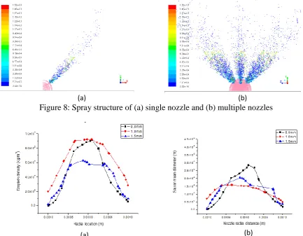
Spray characteristics is the main consideration in the combustion analysis which can be determined by droplet size, spray penetration and spray angle. In this paper, determination of spray characteristics was obtained along the 10 mm length after the nozzle exit. In Fig. 8 (a), it shows the spray structure of single nozzle compared to eight holes nozzle8 (b).
[image:4.595.74.508.272.609.2]Droplet density has significant effects on the evaporation rate, hence influence the combustion of the burner. Higher density contributes to the higher evaporation rate [1].Fig. 9 (a) indicates the droplet spray at radial location of the nozzle. The trend shows the droplets density of diameter 1.0 mm produces the highest droplet density, followed by 0.8 mm and 1.5 mm. The next parameter is Sauter mean diameter (SMD), the diameter of a sphere droplet with similar volume per surface area ratio measured at 10 mm downstream of the nozzle. Low value of SMD indicates higher surface area, hence improve the evaporation and mixture formation of the nozzle injector [9]. Fig. 9 (b) displays diameter 1.0 mm gives the lowest SMD, followed by nozzle diameter of 1.5 mm and 0.8 mm.
Figure 8: Spray structure of (a) single nozzle and (b) multiple nozzles
Figure9: The radial profile of the droplets. (a) Droplets density (b) SMD radial location in the spray
Conclusion
In this paper, effects of different nozzle orifice geometry on spray and combustion processes were measured. The study found that the diameter of the nozzle plays a very important role on the spray characteristics of premix injector. An increase in the diameter of nozzle hole will reduce the velocity components at the nozzle exit. This will also affects its TKE, hence influences the cavitation formation inside the nozzle.
In addition, the droplet SMD produced by large diameter nozzles produce large SMD value. For 0.8 mm diameter nozzle hole, the velocity of the injected spray is higher. Thus, small diameter nozzle will produce the small SMD. Moreover, small diameter nozzles will produce the highest density of droplets compared with a smaller nozzle size. This is because large-diameter nozzle droplet evaporation rate is lower than the droplets of smaller diameter nozzle. In conclusion it can
be concluded that the injector nozzle diameter of 0.8 mm is more suitable for premix injector on a burner. At a diameter of 0.8 mm, the flow velocity is higher, the length of the fragmentation is low, small SMD value and droplet density is high.
Acknowledgement
The authors would like to thank the Ministry of Education, Malaysia for supporting this research under the Research Acculturation Grant Scheme (RAGS)VOT R024.
References
[1] M.F.M. Yasin , R.S.Cant, C.T. Chong, S. Hochgreb, Discrete multicomponent model for
biodiesel spray combustion simulation. Fuel 126 (2014) 44–54.
[2] S. Soma, A.I.Ramirez, D.E. Longman, S.K. Aggarwal, Effect of nozzle orifice geometry on
spray, combustion, and emission characteristics under diesel engine conditions. Fuel 90(2011)
1267–1276.
[3] T. Yatsufusa, Y. Kidoguchi and D. Nakagawa, Improvement of emissions and burning limits in
burner combustion using an injector on the concept of fuel-water internally rapid mixing. Journal of Energy and Power Engineering 8(2014) 11-19.
[4] Amir Khalid and Bukhari Manshoor, "Effect of High Swirl Velocity on Mixture Formation and
Combustion Process of Diesel Spray", Applied Mechanics and Materials Vols. 229-231 (2012), Trans Tech Publications, Switzerland, pp 695-699.
[5] M. Farid Sies, Norrizal Mustaffa, Hanis Zakaria, Hamidon Salleh, B. Manshoor, Amir Khalid,
“A Review of the Concept of Fuel-water Internally Rapid Mixing Injector in Burner System”, Applied Mechanics and Materials Vols. 465-466 (2014), Trans Tech Publications, Switzerland, pp 296-301.
[6] Y.S. Lin., H.P. Lin, Study on the spray characteristics of methyl esters from waste cooking oil
at elevated temperature. Renewable Energy 35 (2010) 1900-1907, 2010.
[7] L. Yang, Q. Fu, Y. Qu, W. Zhang, M. Du, B. Xu, Spray characteristics of gelled propellants in
swirl injectors. Fuel 97 (2012) 253–261.
[8] T.N.C. Anand, A. M. Mohan, R.V. Ravikrishna, Spray characterization of gasoline-ethanol
blends from a multi-hole port fuel injector. Fuel 102 (2012), 613–623.
[9] Amir Khalid, S. H. Amirnordin, L. Lambosi, B. Manshoor, M. F. Sies, H. Salleh, “Spray
Characteristic of Diesel-Water Injector for Burner System”, Advanced Materials and Research Vols. 845 (2014), Trans Tech Publications, Switzerland, pp 66-70.
[10]Chou, B.M.W.Y.a.S., Cavitation in injector nozzle holes- A parametric study. Engineering