A COMPARATIVE ANALYSIS OF DATA REDUNDANCY AND EXECUTION TIME BETWEEN RELATIONAL AND OBJECT ORIENTED SCHEMA TABLE
SALIM TAHIR ALAKARI
A dissertation submitted in partial
fulfillment of the requirements for the award of the Degree of Master of Computer Science (Software Engineering)
The Department of Software Engineering
Faculty of Computer Science and Information Technology Universiti Tun Hussein Onn Malaysia
v
ABSTRACT
ABSTRAK
vii
CONTENTS
\ CHAPTER 1 INTRODUCTION
1 Background of Study
1.1 2 Problem Statement 1.2 3 Project Objectives 1.3 3 Scope of Study
1.4
4 Significant of Study
1.5 4 Dissertation Outline 1.6 5 Chapter Summary 1.7
CHAPTER 2 LITERATURE REVIEW
6 Introduction
2.1
6 Entity Relationship Diagram
2.2
7 Class Diagram
2.3
9 Comparing Object Oriented Model and Relational Model
2.4 10 Data Redundancy 2.5 11 Normalization Technique 2.6 12 Relational Database 2.7 13 Object Oriented Database
2.8
14 Compare Relational and Object Oriented Database
2.9 i TITLE vii DECLARATION iii DEDICATION iv ACKNOWLEDGEMENT v ABSTRACT vi ABSTRAK vii CONTENTS x LIST OF TABLES
xi LIST OF FIGURES
xiii SYMBOLS AND ABBREVIATIONS LIST
17 Structure Query Language
01.2
18 Relational Technique in Designing Database
2.1.
19 Object Oriented Technique in Designing Database
2.10
19 Compare Relational and Object Oriented Technique
2.13 21 Related Work 2.14 23 Chapter Summary 2.15
CHAPTER 3 METHODOLOGY
24 Introduction
3.1
24 The Flow Chart of Research
310
26 Comparison Redundancy
313
26 Calculate Data Redundancy
3.3.1
28 Calculate Redundancy Attributes
3.3.2
28 Query Execution Time between RDBMS and OOBDMS
3.4
30 Design Relational Database
314.1
30 Creating Database Tables in RDBMS
3.4.2
31 Design Object Oriented Database
3.4.3
30 Database for Objects db4o
3.4.4
32 Creating Class
3.4.5
33 Creating an Object
3.4.6
33 Chapter Summary
3.5
CHAPTER 4 IMPLEMENTATION AND RESULTS ANALYSIS
34 Introduction
4.1
34 Over View on Two Case Studies
4.2
34 First Case Study
4.2.1
34 Second Case Study
4.2.2
35 Implementation of Relational Technique
4.3
35 Create Entity Relationship Diagram
4.3.1
38 Generate Schema Table From ER Diagram
4.3.2
42 Implementation of Normalization Technique
4.3.3
46 Implementation of Object-Oriented Technique
4.4
46 Generate Class Diagram From ERD
4.4.1
48 Object-Oriented Concept
4.4.2
51 Generate Schema Table from Class Diagram
ix 55 Analysis of Result Data Redundancy in Course Database
4.5
56 Analysis of Result Data Redundancy Attributes in HMS
4.6
57 Analysis of Result Redundancy Attributes
4.7
58
Comparative Analysis of Redundancy Relational and Object
Oriented
4.8
61
Implementation of Query Execution Time RDBM and
OODBMS
4.9
61 Software Implementation
4.9.1
62 Calculate Query Execution Time in RDBMS
4.9.2
64 Calculate Query Execution Time in OODBMS
4.9.3
66
Analysis of Query Execution Time between RDBM and OODB
4.10
68 Comparative Analysis of Query Execution Time RDB and
OODB 4.11
70 Chapter Summary
4.12
CHAPTER 5 CONCLUSIONS
73 Objectives Achievement
5.1
73 Research Findings
5.2
74 Future work
5.3
75 REFERENCE
LIST OF TABLES
9 Comparing OODBMS and RDBMS Modelling
2.1
15 The Equality of Various Concept in RDBMS and OODBMS
2.2
16 Comparing OODBMS and RDBMS Considering Their Objective
2.3
20 Key Difference between Relational and Object Oriented Analysis and
Design 2.4
29 Explain of Calculate Query Execution Time Function
3.1
55 Experimental Results of Data Redundancy in Course Database.
4.1
55 Result of Compare Data Redundancy in Course Database
4.2
56 Experimental Results of Data Redundancy in HMS.
4.3
56 Result of Compare Data Redundancy in HMS
4.4
57 Comparative Result about Redundancy Attributes
4.5
57 Result of Compare Redundant Attributes
4.6
62 Execution Time for 4 Queries in Relational Database HMS
4.7
63 Execution Time for 4 Queries in Course Relational Database
4.8
64 Queries Execution Time in Hospital Object Oriented Database
4.9
65 Execution Time for 4 Queries in Course Object Oriented Database
4.10
66 Comparing Query Execution Time for Hospital Management System
4.11
66 Comparing Query Execution Time for Course Database
4.12
67 Result of Query Execution Time between RDBMS and OODBMS
4.13
68 Result of Query Execution Time between SQL and DB4O.
xi
LIST OF FIGURES
8 Class Icon in Class Diagram
2.1
.8 Relational Technique in Designing Database
2.2
.9 Object Oriented Technique in Designing Database
2.3
0. Framework of Auto Generate Tool for UML Class Diagram
2.4
05 Flow Chart Research
3.1
06 Enter Data Entry in Schema Table Doctor
3.2
07 Data Redundancy
3.3
07 Calculate Total Data Redundancy in Attribute
3.4
07 The Result from SQL Query
3.5
08 User Friendly Window for Hospital Management System
3.6
09 The C# Code Function Get Timer
3.7
09 Execution Time of Query by Millisecond
3.8
32 Created Relational Database in SQL Server 2012
3.9
3. Show the SQL Statement to Create Relational Database
3..2
3. Insert Data in Doctor Schema Table
3...
3. Difference between db4o and Relational Database
3..0
30 C# Code for Create Appointment Class in HMS
3..3
33 Add an Object
3..4
35 The First page in Visual Paradigm Program
4.1
36 Add New Model
4.2
36 Write the Name for New Model.
4.3
36 Select Entity Relationship Diagram.
4.4
37 Entity Relationship Diagram for Hospital Management System
4.5
38 Entity Relationship Diagram for Course Database
4.6
38 Generate Schema Table from ER Diagram
4.7
39 Generate SQL Dialog Box
4.8
39 Database Configuration
39 Database Configuration Save
4.10
4. Create Schema Table for Hospital Management System
4.1.
40 Generate Schema Table for Course Database
4.10
40 Normalization Techniques
4.13
43 Schema Tables Normalization until 3NF in Course Database
4.14
45 The Schema Tables Normalization until 3NF for HMS.
4.15
46 Generate Class Diagram from ER-Diagram
4.16
47 Class Diagram for Hospital Management System
4.17
48 Class Diagram for Course
4.18
49 Inheritance Diagram to Table Mapping
4..9
52 Class Diagram Hospital Management System
4.20
5. Generate Database from Class Diagram.
4.21
5. Show Database Code Generation Dialog
4.22
50 Generate Schema Tables
4.23
50 Generate Schema Table for Course Class Diagram
4.24
54 Create Schema Table for Hospital Management System Class Diagram
4.25
58 Repeating group
4.26
58 Create New Rows for Repeating Groups
4.27
59 Reduce Data Redundancy in first Normal Form
4.28
62 Inheritance in Hospital Class Diagram
4.29
6. First Page of Visual Studio 2010
4.30
60 Execution Time Query for Relational Database HMS
4.31
63 Query Execution Time for Relational Courses Database.
4.32
64 Calculate Query Execution Time in Hospital OODBMS
4.33
65 Calculate Query Execution Time in Hospital OODBMS
4.34
67 Queries Execution Time between RDBMS and OODBMS
4.35
68 store objects in relational database
4.36
69 Store Objects in Relational Database.
4.37
69 The Query Search in Relational Database.
4.38
72 Store Objects as Objects in Object Oriented Database
4.39
7. Global Design in Object Oriented Database.
xiii LIST OF SYMBOLS AND ABBREVIATIONS
1NF - First Normal Form
2NF - Second Normal Form
3NF - Third Normal Form
RDBMS - Relational Database Management System
OODBMS - Object Oriented Database Management System
CD - Class Diagram
ERD - Entity Relationship Diagram
ERD - Entity Relationship Diagram
UML - Unified Modeling Language
AT - Arithmetic Mean Average
SQL - Structure query language
HMS - hospital management system
LIST OF APPENDICES
APPENDIX TITLE PAGE
A Normalization Technique 82
B SQL Query for Calculate Data Redundancy 94
C C# Source Code 99
C.1 Create Classes for Hospital Management System. 99
C.2 Create Classes for Course Database. 106
C.3 Add and Display Objects for HMS 107
CHAPTER 1
INTRODUCTION
1.1 Background of Study
A database is a mechanism to store information or data. Information is something that people use on a daily basis for a variety of reasons. Database should be able to store data in an organized manner. When data are stored in a database, it should be easy to retrieve information. The database stores the data to ease searching, modifying and removing information. Database design is supported by many methodologies and techniques, which contribute to a perfect design (Stephens & Plew, 2001).
multiple times in a database for a variety of reasons. Also this project concerned designing two important types of databases in computer, which are relational database and object oriented database. These databases were designed based on the relational model and the object oriented model. The purpose of this project was to analyse the redundancy problem using the object-oriented technique and relational technique, and then calculating the total data redundancy using SQL query. Also, based on these techniques, relational database and object oriented database were designed and compared based on the query execution time of both types of databases. The comparison was performed by designing a user-friendly window to calculate the query execution time by millisecond in these types of databases.
1.2 Problem Statement
3
1.3 Project Objectives
The objectives of this research are:
(i) To define data redundancy between relational and object oriented techniques using structure query language (SQL) in two case studies.
(ii) To define query execution time between relational database and object oriented database using user friendly window in two case studies.
(iii) To compare the result between relational and object oriented techniques.
1.4 Scope of Study
The scope of study in this project is database design. Database has many techniques and software's works on run and create databases. This project focuses on the design of database using two techniques, which are the relational technique based on entity relationship diagram and object oriented technique based on class diagram, and also by following these steps:
(i) Create ERD by applying the normalization technique until 3NF to generate schema table normalization for two case studies.
(ii) Create class diagram with generate schema table for the two case studies. (iii) Compare the schema table between ERD and class diagram based on data
redundancy and redundancy attributes.
(iv) Create relational database based on ERD and object oriented database based on class diagram.
(v) Create a user friendly window using C# to compare between relational databases and object oriented database based on query execution time.
1.5 Significant of Study
Databases have become more indispensable in our daily life. To deal with data every day and everywhere from cellular phone contacts, medical records, and logistical data to transaction records and many more, they are all stored in databases. It is hard to imagine what the world would be like without databases. Perhaps there would be no ATM, no credit card, no GIS and no airline reservation. The first objective in the project is defining the best database design based on data redundancy, between relational and object oriented techniques. The second objective in this project is to compare between relational databases and object oriented database to define query execution time between two different databases, which are SQL Server 2012 and db4o. The third objective is comparing the result between relational technique and object oriented technique. This enhances the knowledge of the capabilities of these types of databases and their efficiency for the system design.
1.6 Dissertation Outline
5
1.7 Chapter Summary
CHAPTER 2
LITERATURE REVIEW
2.1 Introduction
This chapter discusses the previous studies and will talk about each part of the title study on schema table design based on entity relationship diagram and class diagram also will speak about the techniques.
There are two techniques using for database logical design relational and object oriented techniques. Relational technique is based on entity relationship diagram with normalization and object oriented technique is based on class diagram with generate schema table.
2.2 Entity Relationship Diagram
7 Entity Relationship Diagrams is using for modelling of real world problems by order and organizing the data for a particular area of solicitude. This organized data is called a data model technique, and uses a visual language to draw objects with their interrelationships and other applicable properties call them entities, relationships and attributes respectively (Khabbazi et al., 2010).
An entity-relationship model is one of conceptual impersonation of structured data. ERD is the process of generating these models. The end product of the modeling process is an entity-relationship diagram or ER diagram, a kind of conceptual data model. An ER-diagram is a high-level graphic notation used when designing relational databases management system. Database design is mix interpreting these ER-diagrams to relational database schema. For a given ER diagram, there are many imaginable relational database schemas and the designer should choose the most proper one. In the ER model, elements are spoken to by squares, attributes by circles, relationship between substances by association, the primary keys underlining the attributes and the identities communicating their separate values (Urea & Luis, 2008).
2.3 Class Diagram
A class diagram is one of the static diagrams in UML specification. It is utilized to represent the classes of a system and the relations. A more point by point class diagram can incorporate the features of the entities and additionally their obligations. There are two sorts of features structural and dynamic. Structural features can be subdivided into attributes and associations. Attributes correspond to variables in programming languages. Because of the way that the relationship between classes represents to as variables in programming languages, these are additionally thought to be structural features. In a class diagram the dynamic part of the classes is the operations or functions, which are executed by methods in a programming language. There are five sorts of relations to unite the classes between one another, which are association, aggregation, composition, generalization and dependency (Fernando, 2012).
the enforcement of the system. An object has an express that incorporates the estimation of its attributes and its connections with different objects. Class diagram is built during the analysis of the system and in the object model. The above models represent to client level ideas, not genuine programming classes or components (Harizi, 2012).
[image:19.595.131.497.331.506.2]A class diagram is describing the types of objects in the system and the different sorts of static relationships that exist among objects. A class icon of class diagram is delineated in Figure 2.1 below. A class is an accumulation of group of things that have similar attributes and common behaviour. Classes are made with three sections, including a class name, attributes and operations. An attribute is a property of a class. An operation is an errand that a class can do or an alternate class can do to a class. A class diagram represents the static behaviour of the system1
Figure 2.1: Class Icon in Class Diagram (Tedla & Emanuel, 2004).
Class Diagram gives a set of classes, interfaces and their relationship. Class diagram is the basic modelling technique in the object oriented system. This diagram shows the static perspective of the system. Classes in the class diagram are the essential building block of any object oriented system. Class is the accumulation of similar sorts of object. Attributes and operations are parts of class. Class diagram is additionally one highlight of the sorts of UML specifications. Class diagram describes the object and data structures when planning the application in the object oriented programming and design object oriented database. Class diagram was not a comprehension unpredictable during design the system (Bipsha & Nilanjan, 2013).
Employee Emp id: string Name: string Age: number Salary: currency Getname (); Getage(); Class name
Attributes
9
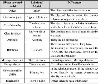
2.4 Comparing Between Object Oriented and Relational Models
[image:20.595.108.521.339.694.2]The differences between an object oriented model class diagram and a relational model entity relationship diagram is the efficiency between these two sorts of data modeling that is represented by the encapsulation in the object of both state and behavior of the object oriented model, while with the relational model just the state prove. It is understand that a relational database is comprised of relations, which sets of tuples, while an object-oriented database is comprised of classes, which sets of classes. Table 2.1 shows the comparison between OODB and RDBM modeling (Gheorghe, 2007).
Table 2.1: Comparing OODBMS and RDBMS Modelling.
Differences Relational
Model Object oriented
model
The object specifies behaviour too Entity
Object
The class of objects contain the common behavior of objects in that class
Types of Entities Class of objects
The class hierarchy includes inheritance, while the scheme includes external keys The data base
scheme Class hierarchy
The instance may have a more restrictive character
Entity tuple or record Class instance
There are no differences Attribute
Attribute
There are no differences. They have the meaning of descriptions, so with the OODBMS, the inheritance have both the state and the behavior
Relations Relations
Class diagram have Message /Interface There are none
Messages/Interface
Class diagram can have Encapsulation There is none
Encapsulation
In the relational model, if the primary key is not identify, the system generates an identify automatically
Primary key Object identifier
(OID)
Object oriented have inheritance There is none
Inheritance
asked as to why and how people are inclined towards a specific conceptual model when they act as database designers. The answer to this question is difficult and involves understanding of several related control. The work is trying, in the direction of discovering the answer of the question. The experimental study, it is concludes these steps (Jain et al., 2009).
(i) The ER model is easily grasped by the beginners
(ii) Learning of the ER model is much faster than that of the OO model.
(iii) For the beginners implementation an ER schema using an RDBMS is much faster than that of the OO implementation.
(iv) Experienced designers or implementers may prefer the OO model.
2.5 Data Redundancy
The important objective is to reduce data redundancy over databases. The different standard of similarity to the element in every domain are presented and contrasted and the design relational for the representation of fluffiness in the fuzzy object oriented database. An endeavour has been using the proportionality relational to reducing the data redundancy in fuzzy object oriented databases. This methodology is focused on considering allotments of the relational and identicalness class that get essential conditions from the relation. Part and comparability classes are additionally used to find out the redundancy easily and efficiently. In that way, a database without errors is depicted. This sort of office will unquestionably enhance agreeable nature of objected oriented databases and improve the ease of use of the database systems (Dutta et al., 2013).
11
2.6 Normalization Technique
The qualifier of the normalization in relational database management system is the procedure of organizing data and reduces data redundancy inside tables. It’s usually contained isolating a database into two or more schema tables and describes relationships between the tables. The objective is to separate data so that additions, deletions and modifications of a field can be made in one table only and after propagated through the rest of the database via the defined relationships. The designer of the ERD introduced the concept of normalization technique and normal forms (NF) and also presented algorithms for relational database normalization into1NF, 2NF and 3NF using their general definitions in a step by step feature )Demba, 2013(.
Normalization Technique is a process of breaking down the given relational schemas focused around their functional dependencies and primary keys to accomplishing the desirable properties of decrease duplication. It goes for making a set of relational tables with least information redundancy that protection consistency and facilitates correct insertion, deletion, and modification. A normalized database is not show various insertions, deletion and modification anomalies due to future updates, which presents a comparative study of manual and automatic normalization using a sequential as well as a parallel algorithm. It is very much time- consuming to use an automated technique to do this data analysis, as opposed to doing it manually. At the same time, the process is test credible and suitable. It produces the dependency matrix and the directed graph matrix, first. It then proceeds by generating the 2NF, 3NF, and BCNF normal forms. All tables are also generated as the procedure proceeds (Verma, 2012).
Normalization is an important technique for the design of relational databases. In the course of the normalization, the functional and multivalued dependency in the tables is determined then the match to normal forms with breakdown of the tables is ensured. The method is a theory based on the strict planning method with many advantages (Czenky & Márta, 2014).
(i) The planning process is adaptable. (ii) It eliminates data redundancy.
(iv) It results in the saving of more space in storing.
(v) May add new tables to the database and new rows to the table without any difficulty.
(vi) It ensures data consistency. (vii) It ensures referential integrity.
(viii) After normalization, you may execute data control in the database more easily. Normalization is a process of analyzing the given relational schemas based on the functional dependencies and using a primary key to achieve the minimum data redundancy. Normalization actually is one of the key issues to transfer out manually in the database design. For improve any software system, the database normalization helps to avoid data redundancy problem. If the relational database is used, it expends time; if missed out any constraint to face the problems. While when on an automate database, it is easy for normalizing the data. The essence of data normalization is to break your data into several tables that will relate to each other based on the data within them. By designing database tables correctly, saving space, minimizing duplicating, protecting the data to ensure its consistency and providing faster transactions by sending fewer data (Sunitha & Jaya, 2013).
2.7 Relational Database
Relational database management system is based on entities and relationship among them. It is a collection of data items design as a set of formally defines tables from which the data can obtain easily. Relational database is considered as the most powerful and reliable database management concepts because it require the data normalization, where redundancy could be eliminated to ensure that there is only one source for all data element in the system, therefore increase the integrity through relationships (Awang et al., 2012).
13 a single fixed length value. Each table will have one or many attributes designated as a primary key. This is important so that each record can be uniquely identified (Butuner & Hakan, 2012).
Relational databases management system is usually lending data structuring in the form of tables. In the relational database model, data are reasonably organized in two- dimensional tables. Each type of information is stored in its own table. A relational database management system enables users to query the tables to obtain data from one or more tables in a very flexible way. The relational database is fascinating from a user’s standpoint because end users often think of the data they want as a table. Although the relational database is considered to be a dramatic improvement over the network and relational models, it does not have two disadvantages. First a relational database requires much more computer memory and processing time than the earlier models. Increases in computer processing speed as well as a constant decrease hardware costs have reduced the impact of its first disadvantage. The second disadvantage is that the relational database allows only text and numerical information to be stored in the database. It did not allow the inclusion of complex object types, such as graphics, video, audio, or geographic information (Suri et al., 2011).
2.8 Object Oriented Database
OODBMS uses object to describe data. It can represent real world and complex relationships; also it can be sent as a hierarchical structure. It is also able to develop systems faster than RDBMS by using inheritance. Inheritance is one of object oriented concepts. Object structure supports encapsulation, concurrency and ad hoc query. Also, it can store many data like images, video, audio, animations and mixed media, and accessing data can be faster because objects can be recover directly by following pointers. It uses one UML diagram and supports inverse relationships. Also, it supports an object identifier OID that is automatically generated by the system. In the OODB model, developer can add any rules by writing codes in one or more functions (Khoualdi et al., 2011).
define a database, with features for creating, altering, dropping tables and establishment constraints. OODB is just a collection of objects and interrelationships among objects. Those objects that resemble in properties and behaviour are orderly into classes. Every class is a container of a set of common attributes and methods shared by similar objects. The attributes or instance variables define the properties of a class. The method is describes and explain the behaviour of the objects associated with the class. A class/subclass hierarchy is used to represent complex objects where attributes of an object itself contains complex objects (Ajita & Satheesh, 2009).
An object oriented database combine object orientation along with databases. If a database management system (DBMS) supports the object oriented data model such as class diagram then it is known as the object oriented databases management system (OODBMS). In the current scenario, there are more object-oriented database products that are available in the market to design database like Object Store, Ozone, Objectivity/DB and db4o. OODBMS starts developing due to the lack of maturity of early day’s products, OODBMS could not get wide acceptance in the market. Many of them were not full-fledged database systems as compared to the relational database systems. Also, the object oriented database in the current scenario and the support of UML are to represent the object-oriented database, as many of the software industries are shifting the old structured database into the object-oriented database )Vipin & Ajay, 2013(.
2.9 Comparison between Relational and Object Oriented Databases
15 languages they use for developing software applications are based on object oriented model, so it’s simple for them to handle object oriented databases. In different case, relational database has standards while object oriented database has lack of standards and there is no suitable model for object oriented databases. Because of the extreme functionality provided by object oriented databases, it makes system more complex than relational databases. Besides this, relational database is better to reduce data redundancy. Object oriented databases are not proper for query based on applications and most of all they lack security )Naeem et al1, 2014(.
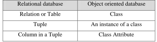
[image:26.595.157.479.537.624.2]The design of relational database is really a process of trying to understand how to describe real world objects within the range of tables in such a way that good performance results and preserving data integrity is possible, but object oriented database design is quite different. In the most part for object oriented database design is a fundamental part of the overall application design process. The object classes used by the programming language are the classes used by the ODBMS. Because their models are consistent, there is no need to transform the program’s object model to something unique for the database manager. There are concepts in the relational database model that are related to those in the object database model. The equivalence of the various concepts in RDBMS and OODBMS are shown in Table 2.2 (Luthra & Sunanda, 2008(.
Table 2.2: The Equality of Various Concepts in RDBMS and OODBMS.
Relational database Object oriented database
Relation or Table Class
Tuple An instance of a class
Column in a Tuple Class Attribute
Table 2.3: Comparing OODBMS and RDBMS Considering Their Objectives.
RDBMS OODBMS
Main objective: ensuring data independence from application programs.
Main objectives: data encapsulation and independence.
Data independence: Data can be reorganized and modified without affecting the mode of using them.
Independence of classes: classes can be reorganized without affecting the mode of using them.
RDBMS stores only data. OODBMS store data and methods.
Data partitioning: data can be partitioned depending on the requirements of the users and on the specific user’s applications.
Encapsulation: the data can be used only through their classes’ methods.
Passive data: the data are passive. Certain operations, which are limited, can be automatically brought into use when the data are used.
Active objects: the objects active. Requests cause objects to execute their methods.
Simplicity: users perceive data as columns, rows/tuples and tables.
Complexity: the structure of data may be complex, involving different types of data.
Separate Tables: each relation/table is separate. The join operator refers data from separate tables.
Chained data: data can be chained so that the methods of classes may bring about increased performance. Structured data such as blobs (binary large objects) are used for sound, image, video etc.
Data non-redundancy: data normalization aims at eliminating or reducing data redundancy. It is used in the stage of designing the database and not in the stage of developing the applications.
Non-redundancy of methods: data and methods non-redundancy is achieved through encapsulation and inheritance. Inheritance helps to reduce the redundancy of methods.
RDBMS performance is related to the level of complexity of the data structure.
Optimizing classes: the data for an object can be interrelated and stored together, so that they may all be accessed by the access mechanism.
Different conceptual model: the model of data structure and data access represented by tables and Joins is different from the model of analysis, designing and programming.
The project must be converted in relational and access tables in accordance with SQL.
17 2.10 Structure Query Language
A structured query language SQL is indispensable and important tools for many types of users as advanced searches, database administrators, and SQL programmers. However, it is hard and tedious for inexperienced users to pose structured queries that accept their query intent, since the users are wanted to be expert in writing the query languages and have a thorough understanding of the schema. On the other hand, they may encounter understanding difficulties, formula problems, and unclear error messages while using SQL. They have to refer to manuals and repeatedly try different SQL queries to obtain expected results (Fan & Zhou, 2011).
Microsoft SQL Server is one of the most famous software that deals with relational databases. Microsoft SQL Server is a relational database management system RDBMS produced by Microsoft company. Also, it is primary query language transact-SQL, an implementation of the ANSI/ISO standard structured query language SQL used by both Microsoft and Sybase. Microsoft SQL Server supports atomic, consistent, isolated, and durable transactions. It includes support for database mirroring and clustering. An SQL server cluster is a collection of identically configured servers, which help disseminate the workload among multiple servers. Also SQL Server supports data partitioning for distributed databases, in addition to database mirroring which allows the creation of mirrors of database contents, along with transaction logs, on another instance of SQL Server, based on certain predefined triggers (Bassil, 2012).
2.11 Relational Technique in Designing Database
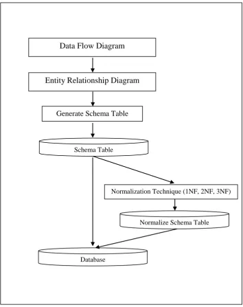
[image:29.595.155.510.246.694.2]
In relational technique approaches, the database is designed based on two diagrams, which are the data flow diagram (DFD) and entity relationship diagram (ERD). Then, the schema table was generated, which can be applied from normalization to end the problem of redundancy. Figure 2.2 illustrates the relational technique in designing the database for software development process.
Figure 2.2: Relation Technique in Designing Database (Saringat, 2014). Database
Generate Schema Table
Normalize Schema Table Schema Table
Normalization Technique (1NF, 2NF, 3NF) Entity Relationship Diagram
19 2.12 Object Oriented Technique in Designing Database
The object oriented approach is a technique that uses a unified modeling language (UML), which contains set diagrams such as use case, sequence diagram, class diagram and others. Normally during the system analysis and design, UML has introduced a class diagram. Figure 2.3 has illustrates the object-oriented technique in designing the database for software development process.
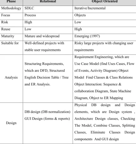
2.13 Comparison Relational and Object Oriented Techniques
This is to show us the comparison between the relational and object–oriented, which are techniques that are based on the analysis and design and also based on
requirements, as shown in Table 2.4 (Motaz, 2010). Database
Generate Schema Table
[image:30.595.168.455.228.549.2]Schema Table
Table 2.4: Key Differences between Relational and Object Oriented Analysisand Design.
Phase Relational Object Oriented
Methodology SDLC Iterative/Incremental
Focus Process Objects
Risk High Low
Reuse Low High
Maturity Mature and widespread Emerging (1997) Suitable for Well-defined projects with
stable user requirements
Risky large projects with changing user requirements
Analysis
Structuring Requirements, which are DFD, Structured English Decision Table / Tree and ER Analysis.
Requirement Engineering, which are Use Case Model (find Uses Cases, Flow of Events, Activity Diagram) Object Model Find Classes & Class Relations Object Interaction: Sequence &
collaboration Diagram, State Machine Diagram, Object to ER Mapping
Design
DB design (DB normalization) GUI Design (forms & reports)
21 2.14 Related Work
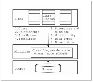
[image:32.595.159.481.314.598.2]A proposal of designing a relational database system based on the object oriented analysis and design is presented. The database system is created by the schema table that is taken from the class diagram. The rules applied are following the object oriented concept. It is based on the relationships among the classes, multiplicity, attributes name, class name, data type and the behaviors of the classes. Besides that, the user is required to insert a record to accomplish a good design of the schema tables to avoid data redundancy. Finally, an automatic editor, known as CDGEST, is proposed in order to automate the process. The framework of the auto generate tool for the UML class diagram in Figure 2.4.
Figure 2.4: Generate Schema Table From Class Diagram (Saringat et al., 2010).
remember the syntax of query to maintain the database management, which is very difficult. However, normal users are not familiar with query languages and database structures, but would like to know the execution time of queries of various RDBMS languages and access data in a more user-friendly window (Rao & Chavan, 2012).
There are two concepts that can cause problems for the novice database designer. Firstly, transferring the concept of a weak entity from an entity relationship model to the UML class diagram and secondly, the notation for structural constraints in different diagramming notations. Also look at the mixture of notations, which students mistakenly use when modeling. This is often the result of different notations being used on different courses throughout their degree. Today, the UML class diagram can be used as a tool in the structured design of databases using the relational model (Byrne et al., 2013).
The comparative study is between the relational and object-oriented systems that identified characteristics of the requirement modelling of the three analytical models namely, relational, object-oriented and semantic, differ significantly. The relational model uses ERD, object-oriented uses class diagrams and the semantic model uses ontology charts. However, the drawing of ontology charts requires greater analytical skills, as compared to ERD or class diagrams. When it comes to data modelling, relational uses relations or tables, but the other two models haven’t so far been successful in suggesting an efficient data model1 These schemes are illustrations of combinations of data before the actual design of databases (Mohammad et al., 2012).
23 The proposal of the design methodology for relational databases based on entity relationship diagram (ERD) and higher normal forms normalization to focus on the issues related to modelling binary relationships, ternary relationships, decomposing ternary relationships to binary equivalents and transforming the same to relations. The impact of applying higher normal forms into relations with composite keys is analysed. A proposed methodology that database designers must follow during each phase of database designed. The most important advantages of this technique help to reduce the proportion of data redundancy during database design (Vimala et al., 2013).
2.15 Chapter Summary
CHAPTER 3
METHODOLOGY
3.1 Introduction
This chapter begins with an overview of the proposed methodology and theoretical conceptual the flow chart research. The methodology explained the way to apply relational technique and object oriented technique in two case studies. Also, the methodology shows the framework of comparing redundancy between relational technique and object oriented technique. With design relational database and object oriented database than compare query exaction time based on user friendly window.
3.2 Flowchart of the Research
The flowchart for the research in Figure 3.1 shows the processes of applying the relational technique and the object oriented technique on two case studies.
The flowchart of the research starts with the case studies on hospital management system and course database. Application of the first technique was the relational technique, which were ERD and the generation of a schema table and normalization in each case study. Application of the second technique was the object oriented technique, which was class diagram with generate schema table in each case study. Also with defined the redundancy between both techniques. Continue with the flowchart with design the relational database and object oriented database for each case study, and then define the query execution time using a user friendly window.
75
REFERENCES
Ali, M. G., & Murtuza, M. G (2011). A Common Database and a Transaction Pool to Reduce Data Redundancy and to Maximize Database Throughput in a Comprehensive Information System of a Particular Domain of Interests. Awang, Mohd Khalid, and Nur Lian Labadu(2012). Transforming Object oriented
Data Model to Relational Data Model. International Journal of New Computer Architectures and their Applications (IJNCAA) 2.3: 402-409. Bipsha Mallick & Nilanjan Das (2013). An Approach to Extended Class Diagram
Model of UML for Object Oriented Software Design. International Journal of Innovative Technology & Adaptive Management (IJITAM).
Bordoloi, S., & Kalita, B. (2013). international journal of computer engineering & technology (IJCET). Journal Impact Factor, 4(6), 219-231.
Butuner, H. (2012). Advantages of object-oriented over relational databases on real-life applications. Research Journal of Economics, Business and ICT, 5.
Byrne, B. M., & Qureshi, Y. S. (2013). The Use of UML Class Diagrams to Teach Database Modelling and Database Design. Friday 5th July 2013 University of Sunderland, 11.
Brandy, M. (2000). Use of entity/relationship diagramming as a technique in the grounded theory approach to social science research. In Irish Academy of Management Annual Conference.
Batory, D., Latimer, E., & Azanza, M. (2013). Teaching model driven engineering from a relational database perspective. In Model-Driven Engineering Languages and Systems (pp. 121-137). Springer Berlin Heidelberg.
Bassil, Y. (2012). A comparative study on the performance of the Top DBMS systems. arXiv preprint arXiv:1205.2889.
Piyayodilokchai, H., Panjaburee, P., Laosinchai, P., Ketpichainarong, W., & Ruenwongsa, P. (2013). A 5E Learning Cycle Approach-Based, Multimedia-Supplemented Instructional Unit for Structured Query Language. Educational Technology & Society, 16(4), 146-159.
Czenky, M. (2014). The Efficiency Examination of Teaching of Different Normalization Methods. arXiv preprint arXiv:1405.1912.
Dutta, S., Sahoo, L., & Dwibedy, D(2013). An Equivalence Relation to Reduce Data Redundancy Based on Fuzzy Object Oriented Database System.
Edlich, S., Hörning, H., & Hörning, R. (2006). The definitive guide to db4o. Apress. Elmasri, R. Fundamentals of Database Systems 3rd ed, 2011.
Tobias Weltner (2013).objects and types. Sponsored by idera application & server management
Fan, J., Li, G., & Zhou, L. (2011, April). Interactive SQL query suggestion: Making databases user-friendly. In Data Engineering (ICDE), 2011 IEEE 27th International Conference on (pp. 351-362). IEEE.
Harizi, Mohammad (2012). The Role of Class Diagram in Estimating Software Size. International Journal of Computer Applications 44.5: 31-33
Jain, S. K., Gore, M. M., & Singh (2009), G. An Experimental Study to Compare ER/EER and OO Models.
Jorge H. Doorn; Laura C. Rivero (2011). Database integrity: challenges and solutions. Idea Group Inc (IGI). pp. 4–5. ISBN 978-1-930708-38-9. Retrieved 23 January.
Joshua M. Horstman (2011). Dealing with Duplicates in Your Data. MWSUG
2011 - Paper S111.
Khoualdi, K., & Alghamdi, T. (2011). Developing Systems by Using Object Oriented DatabasePractical Study on ISO 9001: 2000 System. Journal of Software Engineering and Applications, 4, 666.
Khabbazi, M. R., Ismail, M., Ismail, N., & Mousavi, S. A. (2010). Modeling of traceability information system for material flow control data. Australian Journal of Basic and Applied Sciences, 4(2), 208-216.
77 Kalid Azad (2002). Mathematical Properties of the Average. October 31.
Luthra, S. (2008). Architecture in Object Oriented Databases. In Proc. The National Conference on Challenges and Opportunities in Information Technology. Luthra, S. (2008). Architecture in Object Oriented Databases. In Proc. The National
Conference on Challenges and Opportunities in Information Technology. Mohd Zainuri Bin Saringat (2014). Attributes sensitization in object-oriented design
to improve database structure. A thesis of the doctor of Philosophy in Information Technology.
Motaz K. Saad(2010). "Structured vs. Object Orient Analysis and Design SAD vs. OOSAD".
Naeem, M. R., Zhu, W., & Memon, A (2014). A. New Approach for UML Based Modeling of Relational Databases.
Peter Rob; Carlos Coronel (2009). Database systems: design, implementation, and management. Cengage Learning. p. 88. ISBN 978-1-4239-0201-0. Retrieved 22 January (2011).
Stephens, R. K., & Plew, R. R. (2001). Database design book by Sams Publishing. SABĂU, G. (2007). Comparison of RDBMS, OODBMS and ORDBMS. Revista
InformaticaEconomică,(44).
Saringat, M. Z., Herawan, T., & Ibrahim, R. (2010). A Proposal for Constructing Relational Database from Class Diagram. Computer and Information Science,3(2), P38.
Saxena, V., & Pratap, A. (2013). Performance comparison between relational and object-oriented databases. International Journal of Computer Applications,71(22), 6-9.
Sunitha, G., and A. Jaya (2013). A knowledge based approach for automatic database normalization. International Journal of Advanced Research in Computer Engineering & Technology (IJARCET) 2.5: pp-1816.
Suri, P., & Sharma, M. (2011). A comparative study between the performance of relational & object oriented database in Data Warehousing. International Journal of Database Management Systems, 3(2), 116.
Scott (2012). Visual Studio Express 2012 for Windows Desktop Retrieved on September 13, 2012, from
http://www.hanselman.com/blog/freevsualStudioExpress2012ForWindowsdesktop.aspx
Tedla, K. M., & Grant, E. S. (2004). Application of objectoriented Domain Analysis and Design in the Model Driven Architecture Framework (Doctoral dissertation, University of North Dakota).
Urea, L. (2008). Storing and Searching Scientific Data with a Relational Database System.
Valles-Barajas, Fernando(2012). Using lightweight formal methods to model class and object diagrams. Computer Science and Information .
Verma, S. (2012). Comparing manual and automatic normalization techniques for relational database. IJREAS, February.
Vimala, S (2013). design methodology for relational databases: issues related to ternary relationships in entity-relationship model and higher normal forms. International Journal of Database Management Systems 5.3.
Voore Subba Rao and Vinay Chavan(2012). A User Friendly Window Based Application for Calculation of Query Execution Time for Relational Databases International Journal of Engineering and Advanced Technology (IJEAT) ISSN: 2249 – 8958, Volume-2, Issue-2.