International Journal of Emerging Technology and Advanced Engineering
Website: www.ijetae.com (ISSN 2250-2459, Volume 2, Issue 11, November 2012)487
Simplified HEDI Method For Progressive Transmission of
3-D Medical Image
Archana J.N
11Assistant Professor(CS Department),Atria Institute of Technology, Bangalore
.
Abstract — Progressive Transmission of an image permits
the gradual improvement in the quality. When the size of the image has to be more the progressive transmission helps in restoring the actual quality of the image. This can be used in Medical Image transmission in order to maintain the quality of the image transmission. Also it can be used for picture archiving and communication systems (PACS).It can be used to achieve high effective compression ratio by eliminating the need to transmit the unnecessary portion of the images when the transmission is interrupted. This technique is particularly useful where the bandwidth of the channel is limited and the amount of data is large. In order to send image data progressively, the data should be organized hierarchically in the order of importance, for example from the global characteristics of an image to the local detail. The data structure presented in this paper takes into account the clarity of transmission of the image. The data structure described in this paper is a new algorithm for progressive transmission, Simplified HEDI Algorithm which is based on the HEDI algorithm.
Keywords - HEDI, Progressive Transmission, Simplified
HEDI, Sub Sampling.
I. INTRODUCTION
Due to the advances in multi-media applications and digital imaging technology, obtaining high-resolution digitized images from databases over a computer network is becoming more popular than ever. This has led to a growing need for compressing images, both for archival and transmission. In general, lossy compression techniques provide an order of magnitude compression ratio (20:1 to 30:1) than that of lossless compression (2:1 to 4:1). Nevertheless, some applications such as telerdiology do not tolerate any loss of fidelity when images are sent or accessed over a network interactively for the purpose of viewing and analysis. Since the typical resolutions of such images ranges from 1K x 1K to 4K x 4Kwith 8 to 12 bits per pixel, it takes from several minutes to an hour to send one complete image even with dedicated data phone lines. A hybrid method based on a combination of lossy and loss less techniques has been suggested to utilize merits from two techniques: a higher compression ratio from the first and a perfect reconstruction from the latter.
The method, however suffers from two major disadvantages. First, depending on the compression technique employed, it requires two different data formats for each method: one for lossy compression and the other for residual error image between the original and the reconstructed image using lossy compression technique. Second, the compression ratio of the combined method tends to yield higher entropy than that of the loss less only case.
International Journal of Emerging Technology and Advanced Engineering
Website: www.ijetae.com (ISSN 2250-2459, Volume 2, Issue 11, November 2012)488 This service can be accomplished by progressive transmission. Algorithms that satisfy these requirements are suggested by several researches. It includes low-bandwidth channels for long-distance switched communication, as in PACS applications. The architecture described in this project addresses the issues of efficient computations required to build hierarchical structures for compression and decompression, since progressive transmission requires accessing the entire image, which in turn depends on fast access to large amounts of hierarchical image data [1].
1.1 Progressive transmission
Progressive transmission of an image permits the initial reconstruction of an approximation followed by a gradual improvement of quality in image reconstruction. In applications for picture archiving and communication systems (PACS) or multimedia, the concept of progressive transmission is of particular importance in browsing large image files. It can be used to achieve high effective compression ratio by eliminating the need to transmit the unnecessary portion of the images when the transmission is interrupted. This technique is particularly useful where the bandwidth of the channel is limited and the amount of data is large. In order to send image data progressively, the data should be organized hierarchically in the order of importance, for example from the global characteristics of an image to the local detail. There are two types of data structures for progressive transmission depending upon the encoding method employed: transform based encoding and spatial encoding .In a transform-based encoding approach, the image is first divided into a set of contiguous non overlapping blocks. Then each block is transformed into a set of transform coefficients, for example using DCT. The coefficients are then quantized appropriately before initiating its transmission. On the other hand, a spatial approach, like pyramidal encoding, generates a set of image frames at different resolutions. An image is successively reduced in spatial resolution and size by sub sampling or averaging. Approximation of an image can be obtained using a single frame or a combination of frames in pyramid from top to bottom level naturally constitutes a progressive transmission. At the receiving end, progressive expansion from the top level is done using the technique corresponding to that used at the sending end.
The speed or time for compressing and decompressing is another important issue for image archival purposes. In most medical applications, for example, decompression is done more often than compression, since an image is generally compressed and stored in an archive to be used later for clinical purposes.
The architecture described in this project addresses the issues of efficient computations required to build hierarchical structures for compression and decompression. Since progressive transmission requires accessing the entire image which in turn depends on fast access to large amounts of hierarchical image data. The concept presented in the paper [1] adopts HEDI loss less compression method for basic compression scheme. HEDI, suggested by W.Y Kim, is an abbreviation of Hierarchy Embedded Differential Image. This algorithm almost satisfies 3 requirements mentioned before, and encoding and decoding of this algorithm can be implemented in a simple hardware because main concept of this algorithm is very simple and
homogeneous. This advantage ensures high-speed
compression and decompression [7].
1.2 Hierarchy embedded differential image
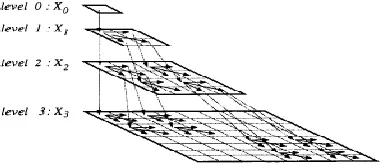
[image:2.612.350.540.613.696.2]Progressive transmission is a method of data transmission that provides a coarse to fine description as the data flows into the system. This is done by sending the global shape information of the image first, then followed by sending the detail information later to complete the image. Pyramid structure is a data structure, which arranges data in levels. There are several types of pyramid structures: mean-pyramid, difference pyramid, and reduced difference pyramid, etc. Among these, reduced difference pyramid is superior to others in the viewpoint of transmission and compression efficiency. Mean pyramid is a structure whose higher-level value is only mean of lower level blocks. Since this structure adds only mean image data to original image, the overall size increases. Reduced Difference pyramid (mean sampling) is a structure whose higher-level value contains a mean value and lower level value contains a difference between original image and mean image. This structure can reconstruct the original image without any additional data space. One of the most important characteristics of HEDI is its capability of progressive transmission. HEDI can be recognized as superset of this reduced difference pyramid. In HEDI algorithm, pyramid like Fig 2.1 is constructed by an initial value and residual value for this initial value.
International Journal of Emerging Technology and Advanced Engineering
Website: www.ijetae.com (ISSN 2250-2459, Volume 2, Issue 11, November 2012)489 The procedure for embedding hierarchical data structures in an image plane of the same size is described below. In these structures, its predictor represents each block. The predictor of a block is determined either by sub sampling, or by a mean-sampling method. Each method can use either a 2x2 or a 3x3 block. Also, a hierarchy can be built using a top-down or a bottom-up approach. Since both these approaches are similar, the method of building the structure in top-down manner is described here[2].
II. HEDIFOR 2DIMAGES (2DHEDI)
2.1. Sub-sampling Method
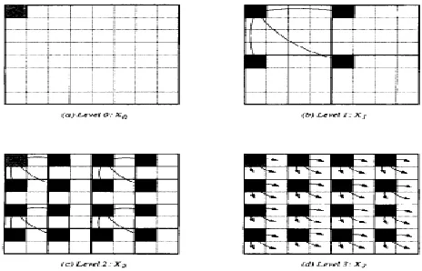
Let (X1) be a set of image frames in a conventional pyramid form, as shown in Fig, 2.1. The number of pixels in an image frame, x1 is s1 x s1. Here / denotes level number, with the lowest resolution level 0 at the top; and level L with the highest resolution same as the original image, XL. As the level increases, so does the resolution of the image frame Xl at level l, forming the pyramid structure. Fig 2.2 depicts a 2 x 2 sub sampling method for a complete image of size 8 x 8. In this figure, frame X0 in (a) is the shaded pixel, and X1, in (b) has four shaded pixels in this sub sampling method, the predictor of a block is defined as the first pixel of the block. Initially the predictor of the hole image XL is the first pixel in raster scan (shaded pixel in Fig. 2.2 (a). Then the image is decomposed into 4 equal quadrants of size 2 L-1 x 2 L-1 each , and the next frame of image is then formed from predictors of these 4 blocks. The predictor of the first block at level 1 is the same as that of level 0, and it becomes the parent node for the remaining three blocks. To construct HEDI, the residual error which is the difference between the parent node and predictor’s own pixel value at this level, is computed and stored at the same location in YL. These difference values are illustrated by solid arrows in Fig. 2.2. At any level 1, only three children nodes of each block in YL are computed, and the number of blocks grow by (2x2)l-1, Therefore, the actual number of values stored in YL at each level 1 is 3 x (2x2)l-1. Here 1 is larger than 1 since there is only root node and no children nodes at the top level, This process is repeated until we reach the bottom level where the block size reduces to 1 x 1 The total number of predictors in Yl from level 1 to L is computed as.
∑ 3 x (2x2) l-1 = 2L x 2 L-1………...……2.1
[image:3.612.332.564.139.288.2]Which is one pixel less than the size of XL.
[image:3.612.347.566.326.391.2]Fig. 2.2. 2 x 2 method on an 8 x 8 image(2D HEDI-Sub Sampling)
Fig 2.3 Computation in HEDI with block size 2x2
International Journal of Emerging Technology and Advanced Engineering
Website: www.ijetae.com (ISSN 2250-2459, Volume 2, Issue 11, November 2012)490 Hence for a sub sampling method, it is better to use a top-down approach than a bottom – up one.
2.2 Mean Sampling Method
The sub sampling method described yields poor quality images suffering from the blocky effect at the intermediate levels of transmission. One way of reducing the effect is to use a low pass filter such as averaging. Therefore, in a mean sampling method, the predictor of a block is the mean of the block .A 2 by 2 mean- sampling method was originally described by Wang et al. This method is based on computing circulars errors as depicted in fig 2.2(b). In this method, for every 2 x 2 block of image at any level l., we compute the mean and difference values by going around the window as shown by arrows in fig 2.2 (b). In this figure yr,c is the mean of the block, and yr,c+s, yr+s,c and yr+s,c+s are the corresponding errors . The algorithm described above builds HEDI using 2 x 2 block with the mean- sampling method with circular differences HEDI-CM2. We start at level L (eg., at level 2 in fig 2.5) and compute the mean and errors of each of block of 2 x 2 pixels as described above the mean values are sent to level (L-1) above and the errors are retained at the same level. This procedure continues until we reach level 0. Once the HEDI is constructed, the progressive transmission begins by transmitting the mean of the image obtained at level 0. Then for each level l, the errors are transmitted for all the blocks at that level when the mean value is transmitted, it is sent as an integer, hence yr, c has to be rounded before sending . One drawback of the circular difference method is that during reconstruction, the four have to be computed sequentially because of the circular differences. The drawbacks of the above mean scheme can be avoided by using the radial difference scheme described earlier. As before, the mean value is rounded and transmitted as an integer. However, in this case, the transmission is lossless because it is possible to recover the original image at the receiving end. Hence the RM2 method described above is a lossless method for progressive transmission. HEDI’s constructed by RS and CS methods are different, but the intermediate image frames at the receiving end are the same. In other words, the set of intermediate image frames reconstructed at the receiving end using RS method is the same as those of using CS method. Similarly, the set of reconstructed image frames using RM is the same as those using CM method. Thus four hierarchical structures (RS2, CS2, RM2, CM2) were constructed using the 2-D HEDI.
2.3. HEDI for 3D Images (3-D HEDI)
As aforementioned, medical image has two major characteristics. Generally, it has a large size. Because medical doctors want to hold every one little bit of analog source image, one medical image might have more than 100,000,000 pixels. Some defects from lossy image compression may confuse medical doctors. This might cause a serious situation, therefore, lossless compression methods are usual for medical image. Lossy compression methods can commonly provide higher compression efficiency about 10 times than lossless methods. For this reason, attempts to introduce lossy compression method into medical field are continuously made using near-lossless scheme. When the amount of data is very large, as a 3-D medical image, the progressive transmission plays an important role in viewing or browsing the image. The data structure takes into account of inter frame correlation as well as intra frame correlation of 3-D images. This type of data structure has been termed as the 3-D hierarchy embedded differential image(3-D HEDI) as was derived from the earlier HEDI structure. The concept of 2-D HEDI can be extended to any multidimensional image. An M. dimensional (M-D) image is successively reduced in spatial resolution and size using mean–sampling (or) sub-sampling. In the HEDI encoding step, the M-D image is decomposed into a set of non-overlapping 2M blocks , ie., 2 x 2 pixel blocks in a 2-D case, and 2 x 2 x 2 pixel blocks in a 3-D case, as illustrated in fig 2.4. In a 2-D image, the parameter l is used to index levels and r, c to index row and column numbers of blocks, respectively, and k to index pixels within a block[1][4].
International Journal of Emerging Technology and Advanced Engineering
Website: www.ijetae.com (ISSN 2250-2459, Volume 2, Issue 11, November 2012) [image:5.612.98.236.137.422.2]491
Fig.2.4. 3D HEDI applied to an 8 x 8 image (a) Level 2 (b) Level 1 (c) Level 0
III. SIMPLIFIED HEDIMETHOD
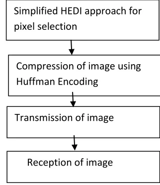
The first pixel of the image is used as the Predecessor, using this first pixel all the other pixels of the Image are referred .Thus the dependency can be decreased while processing the image. Also the calculation can be performed faster . HEDI algorithm is used in extended form to support color images. Since Haar Wavelet technology is used on an image it decreases the dependency of the image. Then the image is compressed using the Huffman Coding method and then the compressed image is transmitted to the receiver end. Simplified HEDI approach can also done for transmitting 3D images. The basic specification of using the Haar wavelet technique is explained below:
3.1 Specification of the Haar Wavelet Technique
The Haar Wavelet is probably the simplest wavelet to understand. Consider two numbers a and b, neighboring samples of a sequence. a and b have some correlation (hopefully) of which has to take advantage. A simple linear transform has been used to replace a and b by their average s and difference d.
s = (a + b)/ 2 d = b – a
The aim is to reduce the number of bits required for d, which will be the case if a and b are highly correlated. This computation can be reversed to recover a and b:
a = s - d/2 b = s + d/2
This is the idea behind the Haar Wavelet. Consider a signal sn of 2n sample values. For each pair of values, we
apply this average and difference transform. There are 2n-1 such pairs, producing that many average and difference values. We can think of the averages as a coarser resolution version of the original signal, and the differences as the higher resolution details. If the original signal is highly correlated, the coarse representation of the signal is very close to the original, and the details can be represented efficiently. We can then apply the same average/difference transform to the coarser signal, splitting it into a yet coarser signal and more details. This transform can be applied until there is but a single signal value and a whole lot of detail values. The remaining signal is the average of the entire signal, and can be thought of as the DC or zero frequency of the original signal. The error images which are also transmitted may be considered using the same approach. An additional advantage of lossless compression methods is that a comparison of their performance can be made perfectly on the basis of their efficiency , when compared to the lossy compression methods, in which a subjective evaluation to indicate whether or not the coding losses are acceptable.
Fig 2.5 Basic design of Data Transmission and Reception
Simplified HEDI approach for
pixel selection
Compression of image using
Huffman Encoding
Transmission of image
[image:5.612.352.513.496.682.2]International Journal of Emerging Technology and Advanced Engineering
Website: www.ijetae.com (ISSN 2250-2459, Volume 2, Issue 11, November 2012)492 In most previous studies, the prediction was generally conducted with a fixed number of predictor variables at fixed locations. Actually, every kind of medical images not only has its own statistical distribution but also demonstrates different properties in different wavelet sub bands. To achieve a more accurate prediction, the number of predictor variables must be adaptively adjusted based on the image’s properties. Thus, instead of relying on a fixed number of predictors on fixed locations and only using one prediction equation, this approach can be used to overcome the multi co linearity problem and employ three prediction equations for different wavelet sub bands to achieve a more accurate prediction [3].
IV. CONCLUSION
In this paper, different hierarchical structures (RS2, CS2, RM2, CM2, RS3, CS3, RM3 and CM3) were constructed using HEDI to achieve lossless compression for progressive transmission of 2D and 3D images. In the progressive transmission using HEDI method, a bit change propagates noise through the subsequent levels of reconstruction and more memory space is required to store the previous levels. Also in this paper, a new algorithm Simplified HEDI method is designed to overcome the drawbacks of the conventional HEDI approach by improving the computational task and hence it provides better reconstruction.
This approach can be extended to support for color images, satellite images, multi-resolution images etc. with suitable modifications.
REFERENCES
[1 ] Yong-Sung Kim and Whoi-Yul Kim “Reversible Decorrelation Method for Progressive Transmission of 3-D Medical Image” IEEE TRANSACTIONS ON MEDICAL IMAGING, VOL. 17, NO. 3, JUNE 1998 383.
[2 ] P.Roos uid MAVicgcver, ”Reversible 3-D decorrelation of medical images”, IEEE lrans. on Medicul Imaging,vol.I2,no.3,413-4201,9 93.
[3 ] Yao-Tien Chen, Din-Chang Tseng “Wavelet-based medical image compression with adaptive prediction” Computerized Medical Imaging and Graphics 31 (2007) 1–8
[4 ] Gabriel Taubi “3D Geometry Compression and Progressive
Transmission” IBM T.J.Watson Research Center y
EUROGRAPHICS ’99
[5 ] Michael G. Strintzis ” A review of compression methods for medical images in PACS” International Journal of Medical Informatics 52 (1998) 159–165.
[6 ] Nikolaos V. Boulgouris, Athanasios Leontaris and Michael G. Strintzis “Wavelet Compression of 3D Medical Images Using Conditional Arithmetic Coding” ISCAS 2000 - IEEE International Symposium on Circuits and Systems, May 28-31, 2000, Geneva, Switzerland.