International Journal of Emerging Technology and Advanced Engineering
Website: www.ijetae.com (ISSN 2250-2459, Volume 2, Issue 11, November 2012)212
Reactive Power Compensation by Controlling the
DSTATCOM
Alpesh Mahyavanshi
1, M. A. Mulla
2, R. Chudamani
3Electrical Engineering Department 1
BVPIT(DS), Umrakh, Bardoli, Surat, India 2,3
SVNIT, Surat, India
Abstract - Voltage sag is the most important power
quality problems faced by many industries and utilities. This paper presents the voltage sag mitigation using DSTATCOM (Distribution Static Compensator). This paper evaluates power balance control algorithm for extracting reference source currents for voltage regulation at PCC (Point of Common Coupling) for DSTATCOM. The voltage source converter (VSC) is used with DC link capacitor as a DSTATCOM. The simulation is done in PSIM for different load condition. Simulation results depict the performance of control of DSTATCOM.
Index Term - Voltage sag, DSTATCOM, Reactive power,
Power balance theory, Control algorithm, Reference source current, PSIM.
I. INTRODUCTION
The majority of power consumption has been drawn in reactive loads such as fans and pumps etc. These loads draw lagging power factor currents in the distribution systems. These excessive reactive power demand increases feeder losses and reduces the active power flow capability of distribution system which also affects the voltage profile. [1-2]
Voltage sag is the most important power quality problems faced by many industries and utilities. It contributes more than 80% power quality (PQ) problems that exist in power systems. According to definition, voltage sag is a reduction in RMS value in AC voltage at power frequency, for duration of a half cycles to a few seconds. [1]. Voltage sags are not tolerated by sensitive equipments used in modern industrial plants, such as process controllers, programmable logic controllers (PLC), adjustable speed drives (ASD), and robotics. It has been reported that high intensity discharge lamps used for industrial illumination get extinguished at voltage sags of 20% and industrial equipments like PLC and ASD are about 10%.[1-5]
In this paper DSTATCOM is controlled by power balance theory (PBT). This power balance theory is modified for compensating reactive power and making voltage profile smooth or to mitigate voltage sag. A PSIM based simulation study of this control strategy for
DSTATCOM is presented. Simulation results
demonstrate the effectiveness of this control algorithm for compensation of reactive power and voltage sag mitigation.
II. CONFIGURATION AND OPERATION OF DSTATCOM
When used in low voltage distribution system, the static compensator (STATCOM) is identified as Distribution STATCOM (DSTATCOM). In general DSTATCOM is used to generate or absorb reactive power.
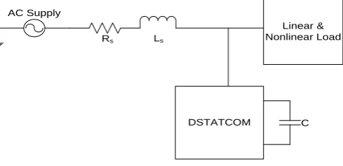
The D-STATCOM is a three-phase and shunt connected power electronics based device. It is connected near the load at the distribution systems. The major components of a DSTATCOM are shown in Figure 1. It consists of a dc capacitor, three-phase inverter (IGBT, thyristor) module, ac filter, coupling transformer and a control strategy [5]. The basic electronic block of the D-STATCOM is the voltage sourced inverter that converts an input dc voltage into a three phase output voltage at fundamental frequency.
AC Supply
Linear & Nonlinear Load
DSTATCOM C
[image:1.595.320.565.440.559.2]Rs Ls
Fig. 1. Basic Building Blocks of the D-STATCOM.
International Journal of Emerging Technology and Advanced Engineering
Website: www.ijetae.com (ISSN 2250-2459, Volume 2, Issue 11, November 2012)213
The current, I, flows through the coupling inductor from the D-STATCOM to the ac system, and the device generates capacitive reactive power. If Vs is greater than Vi, the system 'sees' an inductive reactance connected at its terminal and the D-STATCOM 'sees' the system as a capacitive reactance. Then the current flows from the ac system to the DSTATCOM, resulting in the device absorbing inductive reactive power [4].Vi
Vs
Vi
Vs
(a)
δ θ
Vs
Vi
Ic IL
Ir
Vs
Vi
I IR
IωL
(b)
Vs Vi
Vs
IR
IωL δ
θ IL Ic
Ir
Vi
I
[image:2.595.322.550.219.444.2](c)
Fig. 2 Operation of DSTATCOM (a) No load mode (Vs=Vi), ( b) Capacitive mode, (c) Inductive mode
III. SYSTEM CONFIGURATION
The modelling of DSTATCOM is based on the Modified Power Balanced Theory. Fig.3 shows the simplified system diagram of a DSTATCOM, comprising of a DC link capacitor, IGBT based VSC, coupling Inductor and control strategy.
A three-phase voltage source converter (VSC) is realized using six IGBTs (insulated gate bipolar transistors) switches with anti parallel diodes. Three phase loads may be a lagging power factor load or an unbalance load or a non linear load.
[image:2.595.52.276.234.587.2]For reducing ripples in compensating currents, interfacing inductors are used at AC side of VSC. A RC filter is connected to the system in parallel with the load and the compensator to reduce switching ripples in the PCC voltage injected by switching of DSTATCOM. For controlling the DSTATCOM, the modified PBT based control algorithm is used. [6]
Fig. 3 System diagram with a DSTATCOM
The DSTATCOM is operated for the compensation of lagging power factor balanced load to correct the power factor at source side or to regulate the voltage at PCC.
In ZVR mode, DSTATCOM injects currents to regulate the PCC voltage at the desired reference value of the voltage and the source currents may be leading or lagging currents depending on the reference value of PCC voltage.
IV. CONTROL STRATEGY
For reactive power compensation, a DSTATCOM provides reactive power as needed by the load, and therefore, the source current remains at unity power factor (UPF) and voltage sag is mitigated. Reference source current used to decide the switching of the DSTATCOM has real fundamental frequency component of the load current, which is being extracted by this technique.
Fig. 4 shows the control algorithm based on modified Power Balance Theory [6]. For extracting reference source currents, PCC voltages (Va, Vb and Vc), source
currents (Isa, Isb and Isc), load currents ( ILa, ILb and ILc)
and DC bus voltage (Vdc) of the DSTATCOM are sensed
International Journal of Emerging Technology and Advanced Engineering
Website: www.ijetae.com (ISSN 2250-2459, Volume 2, Issue 11, November 2012)214
The system terminal voltages are given as
(1)
Where Vm and are the peak amplitude and angular
frequency, respectively, of the system voltage at the PCC.
The amplitude of PCC voltage is calculated as,
√
(2)Digital Filter
Real & Reactive
Power P & Q
Compute Dc component of Real & Reactive Power Isnq* Compute Source Referenc e Current
Va Vb Vc
Ila Ilb Ilc LPF LPF PI controller PI controller Vdc Vt Vt* Vdc* Ismp* Ism* Isn* Isa* Isb* Isc* U s a p U s b p U s c p U s a q U s b q U s c q V t Usap Usbp Uscp Usaq Usbq Uscq Vt
Fig. 4 Block diagram of extracting reference source currents
Unit templates in phase with PCC voltages are estimated as,
, , (3)
Unit templates in quadrature with the PCC voltage are,
(
) √
(√
) √ √
( √
) √ √
(4)The three-phase load currents are sensed using Hall effect current sensors and the sensed load currents can be expressed as:
(
)
(
)
(5)Instantaneous active and reactive powers of the load are,
) (6)
Instantaneous active and reactive powers of the load are also written as following which is the combination of DC and oscillating component,
(7) Thus the DC component of Real and Reactive power is estimated as,
Pdc= PL – Posc
Qdc= QL – Qosc (8) The instantaneous load power has two components. First one is a DC component and second one is an AC component. The DC component of the load power can be filtered by a set of either a low pass filter (cut off frequency 10Hz) or a moving average filter (averaging time 1/2f where f source frequency). For Power Factor Correction (PFC) mode, only DC component of the load active power must be supplied by the source. For Zero Voltage Regulation (ZVR) mode, some additional reactive power in addition of AC and DC components of reactive component of the load is supplied by the DSTATCOM to compensate the drop in source impedance.
The active power component of the source currents has two parts. First one is Ismp*, which is required DC
component of the load active power and second one is
Ismd* which is required for the self supporting DC bus of
DSTATCOM. Moreover, the reactive component of the source current has also two parts. First one is Isnq*, which
is required DC component of the load reactive power and second one is Isna* which is required for maintaining the
amplitude of the PCC voltage. The active component of the load current I smp* and Ismd* can be expressed as:
⁄
∫ (9)
Where Vdce= Vdc* −Vdc= error in DC bus voltage. Vdc*
and Vdc are the reference voltage and sensed filtered
voltage of DC bus of DSTATCOM respectively. Kpdand Kid are the proportional and integral gains of the PI
controller over the DC bus voltage of DSTATCOM given in eqn (9).
The amplitude of active component of reference source currents Ism* is,
(10)
Three phase active power component of the reference source currents are as,
(11)
[image:3.595.50.285.211.449.2]International Journal of Emerging Technology and Advanced Engineering
Website: www.ijetae.com (ISSN 2250-2459, Volume 2, Issue 11, November 2012)215
⁄ (12)
The amplitude of reactive component Isna* required for
regulating the amplitude of the PCC voltage can be given as,
∫ (13)
Where Vte =Vt* −Vt= error in amplitude of the PCC
voltage. Vt* and Vtare reference voltage and amplitude of
PCC voltage respectively. Kpa and Kia are proportional
and integral gains of the PI controller over the PCC voltage given in eqn. (13).
The amplitude of reactive power component of the reference source currents Isn* is as,
(14)
Where Isna* is the output of the AC voltage PI
controller and it is required to regulate the PCC voltage at load terminals.
Three phase reactive power component of the referencesource currents are as,
(15)
Total three phase reference source currents are obtained as,
(16)
These extracted reference source currents (Isa*, Isb*
and Isc*)and the respective sensed source currents (Isa, Isb
and Isc) arecompared respectively and the current error is
amplified and used in the current controller to generate the switching signalsfor the DSTATCOM.
PWM switching logic is described as follows for phase a. The sensed supply current (Isa) is compared with its
reference counterpart Isa*in a comparator. Comparator I
consists of a proportional controller. Therefore, the error signal (Isa*-Isa) is processed in the proportional controller
with gain k. The output k (Isa*-Isa) of the proportional
controller is compared with a high-frequency carrier signal in comparator II. The output of comparator II governs ON-OFF status of switches in phase a of DSTATCOM leg.
V. SIMULATION RESULTS AND DISCUSSION
The performance of DSTATCOM is studied with the modified PBT based algorithm. The DC bus voltage of DSTATCOM is selected 800V for the source line voltage of 415V.
The VSC is connected to the network through the AC inductor of 2.3mH. For self supporting DC bus of DSTATCOM, a capacitor of 8000μF is used. Initially considered linear reactive load is 3-single phase load (R=1Ω, L=10mH). The PCC line voltage is considered 415 V, which has nearly 340 V per phase (amplitude). The simulation results are taken for the above mentioned load conditions.
Fig. 5 shows the result of system when DSTATCOM is not connected in the system and load is three single phase reactive load (R=1Ω, L=10mh). The load is applied at time of 0.2 second.
(a)
(b)
(c)
[image:4.595.314.553.277.676.2](d)
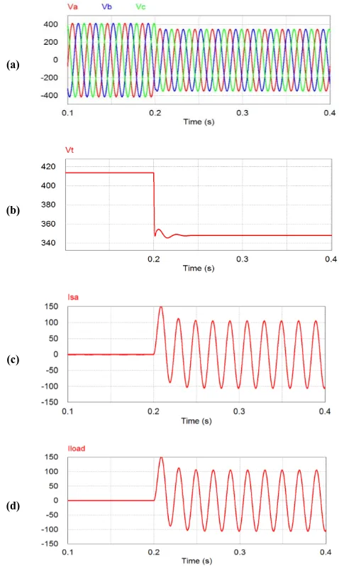
Fig 5 Results without DSTATCOM (a) supply system voltage, (b) PCC voltage, c. source current, d. load current)
International Journal of Emerging Technology and Advanced Engineering
Website: www.ijetae.com (ISSN 2250-2459, Volume 2, Issue 11, November 2012) [image:5.595.51.280.107.228.2]216
After 0.2 second, as load is applied voltage becomes 347 volt. Fig 5(b) shows the waveform of PCC voltage which is 415v for 0 to 0.2 second and becomes 347V after 0.2 second. Fig 5(c) shows source current waveform and for 0 to 0.2 second it is 0A and after 0.2 second it becomes 106 A. Fig 5(d) represents load current waveform which is 0A and after 0.2 sec it becomes 106 amp.Fig. 6 Results with DSTATCOM (a. supply system voltage, b. PCC voltage, c. source current, d. load current)
Fig. 6 shows the result of system when DSTATCOM is connected and load is three single phase reactive load (R=1 Ω, L=10mh). The load is applied at time of 0.2 second. Fig 6(a) shows the waveform of supply system voltage which is 415 volt for the time duration 0second to 0.2 second. After 0.2 second, voltage becomes 415 volt.
Fig 6(b) shows the waveform of PCC voltage which is 415v for 0 t0 0.2 second and becomes 415v after 0.2 second.
(a)
(b)
Fig 7 Supply voltage waveform (a) without DSTATCOM, (b) with DSTATCOM
Fig 6(c) shows source current waveform and for 0 to 0.2 second it is 0A and after 0.2 second it becomes 60 A. Fig 6(d) represents load current waveform which is 0A and after 0.2 sec it becomes 106 amp.
Fig 7(a) shows the supply system voltage when DSTATCOM is not connected. It shows that when load is applied at 0.2 second voltage drops from 415V to 347V. Fig 7(b) shows the supply voltage waveform with DSTATCOM which shows that voltage profile becomes smooth and voltage sag has been mitigated.
(a)
[image:5.595.316.556.166.367.2](b)
Fig 8 Source Voltage and Source current waveform (a) without DSTATCOM (b) with DSTATCOM
(a)
(b)
(c)
[image:5.595.50.287.333.642.2] [image:5.595.317.550.519.722.2]International Journal of Emerging Technology and Advanced Engineering
Website: www.ijetae.com (ISSN 2250-2459, Volume 2, Issue 11, November 2012)217
Fig 8(a) represents the voltage and current waveform when DSTATCOM is not connected with the system. From fig 8(a) we can conclude that current in phase a lags behind the voltage of phase a, whereas from fig 8(b) we can conclude that voltage and current of phase a, are in-phase with each other.(a)
[image:6.595.51.287.211.403.2](b)
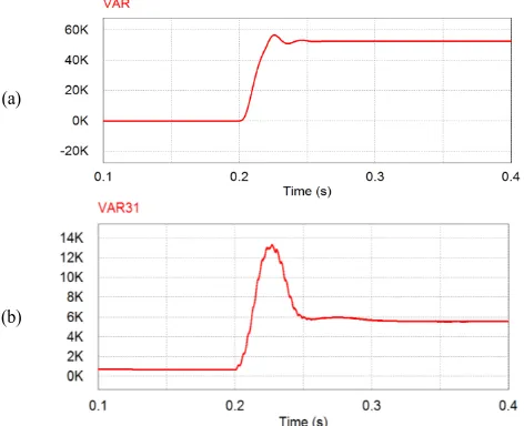
Fig 9 Reactive power (a) without DSTATCOM, (b) with DSTATCOM
[image:6.595.47.282.537.767.2]Fig 9(a) shows waveform reactive power without DSTATCOM which is 52.77KVAR whereas fig 9(b) shows reactive power with DSTATCOM which is 5.6KVAR. Without DSTATCOM power factor of the system when load is applied is 0.305 lag, and it becomes nearly unity (0.985) when DSTATCOM is connected to the system.
Table I
Comparison of result of without and with DSTATCOM
Sr.
No. Quantity
Without
DSTATCOM With DSTATCOM
Before 0.2s
After 0.2s
Before 0.2s
After 0.2s
1 Supply
Voltage 415V 347V 415V 415V
2 PCC
voltage 415V 347V 415V 415V
3 Source
current 0A 106A 0A 60A
4 Load
current 0A 106A 0A 106A
5 Power factor - 0.305lag - 0.985
6 Reactive Power -
52.77kv
ar - 5.6kvar
VI. CONCLUSION
The simulation of DSTATCOM is carried out with modified power balance theory for voltage sag mitigation and also for power factor correction. The algorithm and DSTATCOM has been found very effective for voltage sag mitigation and power factor correction. The DC bus voltage of DSTATCOM has been regulated to its reference value. It has been observed that algorithm is capable to regulate the PCC voltage at reference voltage with compensation of load.
It is observed from the comparison that significant voltage sag is mitigated. Without DSTATCOM reduction in voltage is from 415V to 347V. Thus the voltage sag is
68Vand power factor is 0.305lag, whereas voltage becomes 415V, power factor becomes 0.985 when DSTATCOM is connected to the system. Without DSTATCOM, when load is applied, the reactive power
drawn from source is 52.77KVAR and when
DSTATCOM is connected to the system reactive power drawn from source is reduced and it becomes 5.65 KVAR. Thus reduction in reactive power is 46.27KVAR. From the result table it is also observed that without DSTATCOM current drawn from source, when load is applied is 106Amp, and when DSTATCOM is connected to the system current drawn from source reduces and it becomes 60Amp. Thus DSTATCOM effectively mitigates the voltage sag with improving the power factor also. It is also concluded that DSTATCOM also compensates the reactive power effectively which is observed from the result table.
APPENDICES
Data for simulation:
AC line voltage: 415V (Line to Line), 50 Hz; Source Impedance Rs=0.08ohm, Ls=2mH; Voltage source
converter: DC link voltage=800V, Dc link
capacitor=8000µF, interfacing inductor=2.3mH, switching frequency=9 KHz; For ripple filter, Rr=6Ω,
Cr=90µF, Linear load: R=1Ω, L=10mH; Kpd=0.03,
Kid=0.01, Kpa=10, Kia=2; switching time(Application of
load)=0.2second;
REFERENCES
[1 ] R. C. Dugan, M. F. McGranaghan and H. W. Beaty, Electric Power Systems Quality. 2nd Edition, McGraw Hill, New York, 2006.
[2 ] K. R. Padiyar, “FACTS Controllers in Power Transmission and Distribution,” New Age International (P) Limited, Publishers, New Delhi, 2007.
[3 ] H. Akagi, E.H. Watanable and M. Aredes, “Instantaneous power theory and application to power conditioning,” Jhon Wiley & sons, New Jersey, USA, 2007.
[4 ] Antonio Moreno-Munoz, “Power Quality: Mitigation Technologies in a Distributed Environment”, Springer-Verlag London limited, London, 2007.
International Journal of Emerging Technology and Advanced Engineering
Website: www.ijetae.com (ISSN 2250-2459, Volume 2, Issue 11, November 2012)218
[6 ] Bhim Singh, Sunil kumar, “Modified power balance theory for control of DSTATCOM” IEEE Transaction 2010.
[7 ] P. Jayaprakash, B. Singh, and D.P. Kothari, “Three-Phase 4-Wire DSTATCOM Based on H-Bridge VSC with a Star/Hexagon Transformer for Power Quality Improvement,” in Proc. of ICIIS 2008, Dec. 2008, pp.1-6.
[8 ] B. Singh, P. Jayaprakash, and D.P. Kothari, “Three-phase four-wire dstatcomwith H-bridge VSC and star/delta transformer for power quality improvement,” in Proc. of INDICON 2008, Vol. 2, Dec. 2008, pp.412 - 417.
[9 ] B. Singh, P. Jayaprakash, T.R. Somayajulu, D.P. Kothari, A. Chandra, and K. Al-Haddad, “Integrated three-leg VSC with a zig-zag transformer based three-phase four-wire DSTATCOM for power quality improvement,” in Proc. of IECON 2008, Nov. 2008, pp. 796 -80.
[10 ]B. Singh, K. Al-Haddad, and A. Chandra, “A new control approach to three-phase active filter for harmonics and reactive power compensation,” IEEE Trans. on Power Systems, vol. 13, no. 1, pp. 133– 138, Feb. 1998.
[11 ]B.N. Singh, B. Singh, A. Chandra and K. Al-Haddad, “Design and digital implementation of active filter with power balance theory,” IEE Proc.-Electric Power Applications, vol. 152, no. 5, pp. 1149-1160, September 2005.