Minimizing Median Difference Quantization Error for Image Compression
N. S. A. M Taujuddin Faculty of Electrical and Electronic
Engineering Universiti Tun Hussein Onn
Malaysia
86400 Parit Raja, Batu Pahat, Johor, Malaysia
Rosziati Ibrahim Faculty of Computer Science and Information Technology Universiti
Tun Hussein Onn Malaysia, 86400 Parit Raja, Batu Pahat, Johor,
Malaysia [email protected]
Suhaila Sari
Faculty of Electrical and Electronic Engineering
Universiti Tun Hussein Onn Malaysia
86400 Parit Raja, Batu Pahat, Johor, Malaysia
Abstract—This research emphasis on problem of quantization process in transform-based image compression. In specifying the quantizer, the size of interval is giving huge impact to the quantization performance. Generally, high quantization error will occurred if large interval is used at high difference value bin. Thus, quantizer needs to be design carefully to outfit the value as efficient as possible to reduce the quantization error. Contrary to the traditional approach, that apply uniform or non-uniform quantization step size, the proposed one utilize the high occurrence of zero coefficient by re-allocate the non-zero coefficient in a group for quantization. Then the proposed coder employ quantization error minimization mechanism by calculating the difference median quantization error at each quantization interval class. The results are then compared to the standard transform based algorithm and we found that the proposed algorithm compress the image effectively without harming the quality of the compressed image.
Keywords—quantization; median error difference, wavelet coefficients
I. INTRODUCTION
In highly increasing demand on large data size, compression became a very crucial process [1]. Quantization is one of the essential task in compression. It is sort of procedure that rounding up the quantization to the nearest quantization value by limiting the possible value of transform coefficient to a discrete value. It map integer value of the quantized data to the tone value that represented by some index value. It produce a high speed execution time, but in other hand it also generate high quantization error due to the rounding process [2].
All steps in compression are invertible but not the quantization. Quantization process will reduce the precision of floating point value of wavelet coefficient. These coefficients value is then needed to be expressed in less bit which lead to rounding error. These approximated value is quantized thus creating a lossy compressed imaged [3].
II. RELATED WORK
Quantization algorithm for compression have been studied and are found in scalar and vector domains, as for example, scalar quantization in [2]–[4] and vector quantization in [5], [6].
Scalar Quantization is frequently used in signal quantization. Each signal is tickle as individual and it
quantized independently. It doesn’t take any consideration
of the neighbour value or measurement. While, in contradict, vector quantization grouping all the symbol together and treated them as single unit. This characteristic, increase the performance of quantizer, but at the same time it also increase computational complexity.
Quantization strategy is very essential in building an effective image compression [7] and it is usually employed after transformation. In specifying the quantizer, three consideration need to take into account. Firstly, the desired number of interval. Secondly is the Code-word specification to these intervals and lastly the representation or output value for this interval.
Uniform quantization is one of the earliest quantization algorithm developed [8]. In uniform quantization, an image with N coefficients value range, is divided into L non-overlapping interval. This interval is known as quantization level. The interval i, is defined by designated decision boundaries, as for example (di, di+1) for a finite range start at xmin till xmax. For quantization level i, the reconstruction level
is define as ri.
During encoding process, the quantifier will map the coefficient value x, to a quantization level, that satisfy di≤ x
≤ di+1 to produce quantized value Q(x). While for decoding process, the quantizer will maps the particular given quantized value Q(x) to an approximate reconstructed pixel value. Here, quantization error is introduced.
In contradict, Non-Uniform Quantization has varies boundary and interval[8]. For non-uniform quantizer, the width of each group is different. The element is grouped based on weightage fixed arcording to the needs.
Lloyd Max Quantizer (LMQ) is also one of the well-known quantization algorithm. The basic concept of Lloyd Max Quantizer (LMQ) is to find a set of quantization level (r1,…,rn-1) and a set of step size interval (d1,…,dn-1) that can
minimalize the mean square error (MSE) distribution [9]. In principle, LMQ is also known as Voronoi iteration, where it works in such a way that it produce a smaller quantization interval size in the region where the input has high probability while larger quantization interval size for low probability input [10]. It can be used to construct a close approximation of input. But, LMQ is difficult to implement because of unevenly space decision boundary.
clustering. It then calculates the average point, or centroid of set of data. The centroid is then recalculated for a new cluster, with slightly more even distribution, repeatedly, until the points are very near to the centroid of Voronoi cells. The LMQ is optimally perform on fixed rate quantizer, where same amount of bits are used to represent each quantization level.
Meanwhile, Sreelekha extend this idea in her research by suggesting a quantization algorithm by mapping the coefficients to different clusters using the k-means algorithm. The number of clusters and hence the bit allocation are decided depending on the perceptual based root mean square error allowed for each sub-band [11].
Although these algorithm produce good image quality, but it just basically concern on reducing the cost of compression parameter such as the length of the Code-word, quantization step as well as the quantization boundary without considering the importance of location of significant and non-significant coefficients.
III. PROPOSED METHODOLOGY
In this research, we are proposing a new quantization algorithm to enhance the ability in estimating the interval boundary for optimal quantization. Our approach is different with the previous researches in two main points: (1) the proposed method take zero coefficients in consideration while optimizing the class interval size or step size (2) the group step size is defined by calculating median error difference at each group and it is recursively shift the interval size until it reach to a very minimum error value or no further exchange.
We are proposing a non-uniform quantizer which concern on minimizing the median error value by iteratively shift the group interval size until it reach to a very optimum value.
The reason why median is used in performing the quantization process is the median can clearly describe the central tendency of dispersion among the observed data. Median is also robust since it can eliminate outliers by giving less weighted to outliers. Contradict to mean operation which taking all the weight into consideration. Moreover, median is better compared to mean when it comes to skewed data such as image data. Since the aim of quantization is to quantize the data to be close to correct estimation point, the median is very practical to be use.
The algorithm start with generating a sparse organization of storage. Since the previous thresholding process grounded many near zero coefficients to zero coefficients value, the quantization phase is to take the advantage of this characteristic. The quantization indexing procedure is expressed by:
1 2 0 1 2
1 2 0 1 2
[ , ],| ( , , ) | 0
[ , ],| ( , , ) | 0
i
i
Q p p
j k k
Q
Q k k
j k k
(1)Where i represent either D (diagonal), V (vertical) or H (horizontal) subbands. The wavelet coefficients with
significant value
| ( , , ) | 0
ij k k
0 1 2
are placed in one index and then subject to the following quantization procedure. While| ( , , ) | 0
ij k k
0 1 2
coefficients are retained at its original location.For 2N total wavelet coefficient, the E significant
coefficients element is divided by N to get the initial step size, s, in performing the initial classes, G.
s round
E
N
(2)
G x
i
k,...,
x
k s(3) Then, for each class, the median,
x
is calculated by finding the middle element of distribution.
1 2
thx
j
value
(4)
Where j is the number of element in that class. The median error for each class,
G
is calculated by summing up the total different each element with the class median. Followed by overall median error difference, D for all classes. 0|
|
s k kG
x x
(5) 1 M i iD
G
(6)Next, the interval of each class is reduced or increased to perform a new class set according to estimation proposed by [12]. The whole above process is done iteratively until there is no further exchange or decrease in total class median error.
In order to quantize 2N tone image to only Mtone image,
it is necessary to prepare quantization table. So, each class will get same bit allocation.
The algorithm for proposed quantization algorithm is as follows:
Step 1:
Allocate the location of each coefficients.
Step 2:
Locate the significant coefficients in a group.
Step 3:
For significant coefficients:
a. Select the number of class division, M. b. For each class:
i. Calculate median value of class.
ii. Calculate error value of each bin to class median value.
Repeat (a), until last class.
d. Calculate total median error value for whole class. e. Shift each group step size to get a very minimum
group median error.
f. Repeat step (a) till (e) until no further decrease in total class median error value.
g. Set the quantized value Q for each class.
h. Generate quantization table based on (g).
IV. RESULT AND ANALYSIS
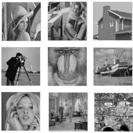
To investigate the functionality of the proposed technique, we develop the algorithm on MATLAB. For the analysis purposes, we use nine standard greyscale test image; namely Lena, Barbara, House, Cameraman, Mandrill, Boat, Woman, Living Room and Hyderabad (see Figure 1). All the images are obtained from University of Southern California, Signal and Image Processing Institute (USC-SIPI) image database. This database has thousands of standard digitize images that widely being used for research in image processing and analysis as well as machinery vision.
To see the performance of quantization process only, a test on minimizing the median quantization error was run without implementing thresholding process. The comparison is done on against Uniform Quantizer and Non-Uniform Quantizer.
Figure 1: Standard test images used analysis. From left to right, top to bottom: Lena, Barbara, House, Cameraman,
[image:3.612.341.553.54.267.2]Mandrill, Boat, Woman, Living Room and Hyderabad.
Table 1: Performance comparison on PSNR between several quantization techniques with the proposed method.
Images Quantization Uniform Uniform Non-Quantization
Minimize Median Quantization Error
% increase compared to Uniform
Quantization
% increase compared to Non-Uniform
Quantization
Lena 19.32 24.06 24.48 26.71% 1.75%
Barbara 20.04 24.07 24.51 22.31% 1.83%
House 19.03 24.07 24.51 28.80% 1.83%
Cameraman 19.77 24.41 24.49 23.87% 0.33%
Mandrill 19.71 24.07 24.51 24.35% 1.83%
Boat 19.5 24.08 24.52 25.74% 1.83%
Woman 19.27 24.12 24.52 27.24% 1.66%
Living Room 20.09 24.11 24.51 22.00% 1.66%
Hyderabad 19.13 24.77 24.42 27.65% -1.41%
Note that for Uniform Quantization, we set the quantization to have 50 equal quantization boundaries. This
means that, the boundary of coefficient doesn’t consider any
pattern of coefficient existence.
While in Non-Uniform Quantizer, the boundary is limited by weightage. At area with more zero coefficients exists, the interval size is wider. While at many significant coefficients exist, the interval size is narrower.
The corresponding PSNR value of each quantization method using various images sample is as shown as in Table
1. As can be seen in Table 1, our proposed Minimize Median Quantization Error technique clearly outperforms another two previous methods. Our proposed method leave
behind Uniform Quantization more than 22% on all images. While have a significant increase more than 1.5% on all images except Cameraman and Hyderabad when comparison is done with Non-Uniform Quantization.
[image:3.612.73.546.362.560.2]explained by the existence of high smooth region that contains a large number of zero coefficients value, leading to a more accurate class interval resizing.
Whereas, the image with high details and edges, such as Hyderabad, cannot utilize the special characteristic of our proposed method since high occurrences of significant coefficients lead to production of large difference error.
In general, Uniform Quantization produce low reconstructed image quality, compared to Non-Uniform Quantizer and the proposed one. While, the proposed one shows a slightly better reconstructed image quality compared to Non-Uniform Quantizer.
The nine sample images used in the experiment are actually representing 3 different image characteristic. Lena, Woman and House is categorize as having low fine details and edges, meaning that it has large area of smooth region. While Barbara, Hyderabad and Mandrill are classified as
having high fine details and edges that representing large area of hard region. However, Boat, Living room and Lake are having a mixture region of low and high fine details and edges.
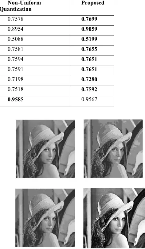
[image:4.612.313.549.238.644.2]Besides, to prove the effectiveness of the proposed quantization method, we run another standard objective image quality measurement, namely, Mean Structural SIMilarity (MSSIM) index proposed by [13]. The MSSIM test is purposely done to measure the quality of reconstructed image. It interpret the human perception towards combination of correction vanished, luminance alteration and contrast distortion. If the reconstructed image produced is exactly same as the original one, it will gain MSSIM value of 1. Means that, more precise reconstructed image to the original one, the MSSIM value will relatively close to 1.
Table 2: Performance comparison using MSSIM for various quantization method on sample images
Uniform Quantization Non-Uniform
Quantization Proposed
Lena 0.4952 0.7578 0.7699
Barbara 0.5615 0.8954 0.9059
House 0.4895 0.5088 0.5199
Cameraman 0.5566 0.7581 0.7655
Mandrill 0.5035 0.7594 0.7651
Boat 0.5062 0.7591 0.7651
Woman 0.4900 0.7198 0.7280
Living Room 0.5391 0.7518 0.7592
Hyderabad 0.4771 0.9585 0.9567
Table 2 shows the performance comparison using MSSIM for Uniform Quantization, Lloyd Max Quantization and the proposed one on various standard image. In all cases, except Hyderabad image, the MSSIM value of the proposed method has a relatively higher value than Lloyd Max Quantization, and has greater difference compared to Uniform Quantization.
This is due to a greater image quality produced from the proposed method. The step size or quantization interval in Uniform and Non-Uniform Quantization didn’t entertain the
special characteristic of each image. Thus, it cause a low image quality and relinquish the boundary estimation.
By minimizing the median error in our method, the significant bin is really fully utilized which significantly influence the reconstructed image quality as can be seen in Figure 2.
Quantization, Non-Uniform Quantization and the proposed method.
V. CONCLUSION
In this research, we are proposing a new quantization method to enhance the ability in estimating the interval boundary for optimal quantization. The proposed method is beneficial in some points: (1) by utilizing the existence of large amount of zero coefficient generated from the thresholding process, an optimum class interval size is produce (2) shifting the class interval position by reducing median quantization error difference lead to a very optimum class interval size and minimizing total quantization error.The proposed method resulting in a good final reconstruction image espeacially for images with large smooth region since it minimize the error during quantization process.
ACKNOWLEDGMENT
The authors would like to thank the Universiti Tun Hussein Onn Malaysia (UTHM), Research, Innovation, Commercialization and Consultancy Management (ORICC) office and Malaysian Ministry of Education for facilitating this research activity under Research Supporting Grant Scheme (RSGS) Vot U109.
Special thanks also goes to Professor Iwahashi Masahiro from Department of Electrical Engineering, Nagaoka University of Technology, Niigata, Japan, for the valuable idea, discussion and comments on this research activities.
REFERENCES
[1] N. S. A. M . Taujuddin, R. Ibrahim, and S. Sari, “Progressive Pixel-to-Pixel Evaluation to Obtain the Hard and Smooth Region for Image Compression,” IEEE Comput. Soc. (6th Int. Conf. Intell. Syst. Model. Simulation), pp. 102–106, 2015.
[2] M. Iwahashi, H. Kobayashi, and H. Kiya, “Lossy compression of sparse histogram image,” 2012 IEEE Int. Conf. Acoust. Speech Signal Process., pp. 1361–1364, 2012.
[3] J. B. Rapesta, F. A. L. I. Blanes, and J. S. Sagrista, “Cell-Based 2-Step Scalar Deadzone Quantization for JPEG2000,” 2014 Data Compression Conf., pp. 143–152, 2014.
[4] J. Sun, Y. Duan, J. Li, J. Liu, and Z. Guo, “Rate-distortion analysis of dead-zone plus uniform threshold scalar quantization and its application - Part II: Two-pass VBR coding for H.264/AVC,” IEEE Trans. Image Process., vol. 22, no. 1, pp. 215–228, 2013.
[5] S. M. Hosseini and A.-R. Naghsh-Nilchi, “Medical ultrasound image compression using contextual vector quantization.,” Comput. Biol. Med., vol. 42, no. 7, pp. 743–50, Jul. 2012.
[6] H. Jiang, Z. Ma, Y. Hu, B. Yang, and L. Zhang, “Medical image compression based on vector quantization with variable block sizes in wavelet domain,” Comput. Intell. Neurosci., vol. 2012, 2012.
[7] H. Kobayashi, M. Iwahashi, and H. Kiya, “Weighted Median Cut Quantization and its Applications,” IEEE Int. Symp. Intell. Signal Process. Commun. Syst., no. Ispacs, pp. 509–514, 2012.
[8] J. Yu and a Usq, “Advantages of uniform scalar dead-zone quantization in image coding system,” 2004 Int. Conf. Commun. Circuits Syst. (IEEE Cat. No.04EX914), pp. 805–808, 2004.
[9] B. Huang and J. Ma, “On Asymptotic Solutions of the Lloyd-Max Scalar Quantization,” no. 2, 2007.
[10] S. M. Borodkin, A. M. Borodkin, and I. B. Muchnik, “Optimal Requantization of Deep Grayscale,” IEEE Trans. Image Process., vol. 15, no. 2, pp. 445–448, 2006.
[11] G. Sreelekha and P. S. Sathidevi, “An HVS based adaptive quantization scheme for the compression of color images,” Digit. Signal Process., vol. 20, no. 4, pp. 1129–1149, Jul. 2010.
[12] Z. Peric and J. Nikolic, “An Effective Method for Initialization of Lloyd–Max’s Algorithm of Optimal Scalar Quantization for Laplacian Source,” Informatica, vol. 18, no. 2, pp. 279–288, 2007.