International Journal of Emerging Technology and Advanced Engineering
Website: www.ijetae.com (ISSN 2250-2459,ISO 9001:2008 Certified Journal, Volume 3, Issue 4, April 2013)
Control Strategy on Doubly Fed Induction Generator Using
PSIM
Niraj Danidhariya
1, Kaumil B Shah
21P.G Student, M.E 4th Semester, Sankalchand Patel College of Engineering, Visnagar.
Abstract- This paper deals with doubly fed induction generator control strategy. This paper includes the results performed in PSIM-9 software such as Performance comparison of output voltage under different loading conditions and output power.
Keywords— Doubly Fed Induction Generator (DFIG), variable speed wind turbine
I. INTRODUCTION
The conventional energy sources are limited and have less pollution to the environment. So more attention and interest have been paid to the utilization of renewable energy sources such as wind energy, fuel cell and solar energy etc. Wind energy is the fastest growing and most promising renewable energy source among them due to economically viable In India. Many applications of wind power can be found in a wide power range from a few kilowatts to several megawatts in small scale off-grid standalone systems or large scale grid-connected wind farms. This type of dispersed power generation causes problems in the electrical connected system. So this requires accurate modeling, control and selection of appropriate wind energy conversion system.
II. DOUBLY FED INDUCTION GENERATOR
Variable speed operation is essential for large wind turbines in order to optimize the energy capture under variable speed conditions. Variable speed wind turbine requires a power electronic interface converter to permit connection with the grid. The power electronics can be either partially-rated or fully-rated. A popular interference method for large wind turbines that is based on a partially rated interference is the Doubly Fed Induction Generator (DFIG) System. In the DFIG system, the power electronic interface controls the rotor currents in order to control the electrical torque and thus the rotational speed. Because the power electronics only process the rotor power, which is typically less than 25% of the overall output power[1], the DFIG offers the advantages of speed control for a reduction in cost and power losses. The paper presents DFIG system simulation in PSIM.
III. BACKGROUND
The mechanical power that can be extracted from a wind turbine is given by
Pw = 0.5 ϱACpV3
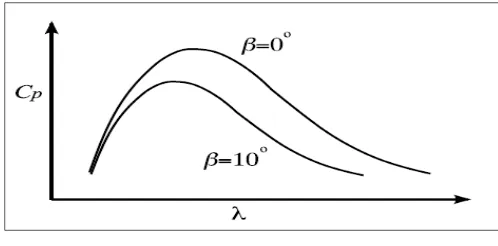
[image:1.612.323.572.337.460.2]Where ϱ is the air density, A is the area swept by the turbine blades, Cp is the performance coefficient of the turbine and v is the wind velocity. A typical performance coefficient curve is shown in Figure where β is the blade pitch angle.
Figure 1 Typical performance coefficient vs. tip speed ratio curve showing the effect of varying the blade pitch angle.
The performance coefficient is dependent on the tip speed ratio λ is given by
λ
Where t is the rotational speed of the turbine and R is the turbine radius. It can be seen that λ should be held constant to harness maximum power from the wind. The turbine rotational speed must therefore increase as the wind speed increases. When the wind turbine reaches its maximum rotational speed however, blade pitch angle control can be employed to shed the excess wind power. Increasing the blade pitch angle decreases the optimum Cp and λ value as shown in Figure 1.
IV. SIMULATION ON DOUBLY FED INDUCTION GENERATOR
A. Simulation on wind turbine
International Journal of Emerging Technology and Advanced Engineering
Website: www.ijetae.com (ISSN 2250-2459,ISO 9001:2008 Certified Journal, Volume 3, Issue 4, April 2013)
[image:2.612.324.572.126.262.2]In this simulation the quantities related to turbine is used in that math function block. Before simulation of DFIG system, simulation of wind turbine is necessary. Although wind turbine generators can be interfaced directly with the power system, the use of a power electronic interface is preferred since it permits variable speed operation and thus offers increased power extraction from the wind. Figure for turbine simulation is shown in figure 2 given below:
Figure 3 wind turbine simulation
Torque output from wind turbine is constant and it is shown in figure 4 given below:
Figure 4 output torque of wind turbine
B. General simulation of DFIG
In doubly fed induction generator both stator and rotor are able to supply the power, but the direction of active power flow through the rotor circuit is dependent on the wind speed and accordingly the generator speed.
Now below the synchronous speed, the active power flows from the grid to the rotor side and the rotor side converter (RSC) acts as voltage source inverter while grid side converter (GSC) acts as a rectifier above the synchronous speed[7], RSC acts as the rectifier and GSC acts as the inverter.
[image:2.612.61.276.224.325.2]So doubly fed induction generator system is superior then conventional system. Simulation of DFIG is shown below:
Figure 5 PSIM Simulations on Doubly Fed Induction Generator
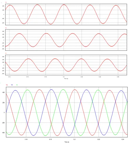
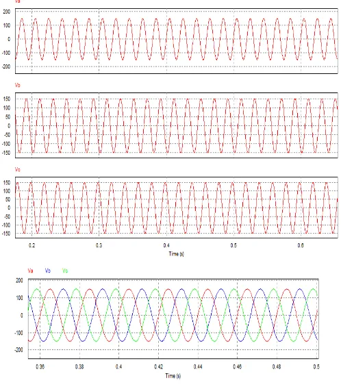
Here output voltage of DFIG system is measured and rotor circuit has to give 3-phase external source. As mentioned that DFIG is capable of supplying power both the side. In this simulation we came to know that the voltage supplied from grid side to DFIG through converter is 5% of the total output. It means that it takes 5% from the grid and supplies other 95% to the grid and frequency is also the same like it[2]. Output voltage from DFIG system is shown in figure 6 given below:
Figure 6 simulation view of output voltage(y axis div. 1 section=200volts)
0 -200 -400 200 400
Va
0 -200 -400 -600 200 400 600
Vb
0.14 0.16 0.18 0.2 0.22 0.24 0.26 Time (s)
0 -200 -400 -600 200 400 600
Vc
0.16 0.18 0.2 0.22 0.24
Time (s) 0
-200
-400 200 400
[image:2.612.49.290.362.476.2] [image:2.612.337.557.392.639.2]International Journal of Emerging Technology and Advanced Engineering
Website: www.ijetae.com (ISSN 2250-2459,ISO 9001:2008 Certified Journal, Volume 3, Issue 4, April 2013)
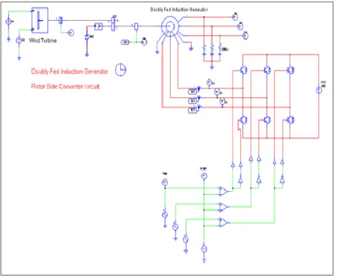
C. Rotor Side Converter circuit of DFIG
Variable speed operation is essential for large wind turbines in order to optimize the energy capture under variable wind speed conditions[14]. Variable speed wind turbines require a power electronic interface converter to permit connection with the grid. The power electronics can be either partially-rated or fully-rated.
Although wind turbine generators can be interfaced directly with the power system, the use of a power electronic interface is preferred since it permits variable speed operation and thus offers increased power extraction from the wind. Variable speed operation also allows wind gusts to be absorbed in the mechanical inertia of the turbine, reducing torque pulsations and fluctuations in the output power. The partially-rated interface processes a portion of the power output of the turbine and offers control flexibility over most of the operating range of the wind turbine[8][9]. A partially-rated interface is typically used with a DFIG where the power electronic interface only processes the rotor power. The main advantages of this scheme are a reduction in the size and cost of the interface converter and a consequent reduction in overall converter losses.
In the DFIG system, the power electronic interface controls the rotor currents in order to control the electrical torque and thus the rotational speed. Because the power electronics only process the rotor power, which is typically less than 25% of the overall output power[10], the DFIG offers the advantages of speed control for a reduction in cost and power losses. Rotor side converter circuit using PSIM is shown in figure 7 given below:
Although wind turbine generators can be interfaced directly with the power system, the use of a power electronic interface is preferred since it permits variable speed operation and thus offers increased power extraction from the wind[13]. Variable speed operation also allows wind gusts to be absorbed in the mechanical inertia of the turbine, reducing torque pulsations and fluctuations in the output power. The partially-rated interface processes a portion of the power output of the turbine and offers control flexibility over most of the operating range of the wind turbine. A partially-rated interface is typically used with a DFIG where the power electronic interface only processes the rotor power. The main advantages of this scheme are a reduction in the size and cost of the interface converter and a consequent reduction in overall converter losses. The purpose of the rotor converter is to control the generator speed to achieve maximum power from the wind over a range of wind velocities. The rotor converter control scheme is based on a multi tiered structure that comprises a speed, power and current control loop. Speed control is implemented by controlling the real power reference to the power control loop[6]. The current controller tracks the power reference by controlling the rotor currents. A partially-rated interface is typically used with a DFIG where the power electronic interface only processes the rotor power. Rotor side converter circuit is rotor side converter which is used for control of rotor.
[image:3.612.328.577.465.658.2]Simulation result for rotor side converter circuit is shown in figure 8 given below:
Figure 8 Rotor Side Converter circuit output results (y axis div. 1 section=500 Volts)
V. RELATIONSHIP BETWEEN TIP SPEED RATIO AND POWER COFFICIENT
[image:3.612.49.293.499.701.2]International Journal of Emerging Technology and Advanced Engineering
Website: www.ijetae.com (ISSN 2250-2459,ISO 9001:2008 Certified Journal, Volume 3, Issue 4, April 2013)
The Betz limit is the maximum theoretic value reached by the power coefficient which is 0.59 for three blades horizontal axis wind turbine used to model the dynamics of the Cp. The values of C1–C9 presented in Table were suggested to represent the aerodynamics of modern wind turbines[3][4],
Cp ( , ) = C1 (
Optimized values of Cp curve equations is given below
C1 C2 C3 C4 C5 C6 C7 C8 C9
0.73 151 0.58 0.002 2.14 13.2 18.4 0.02 0.003
[image:4.612.323.578.411.614.2]At lower wind speed, the pitch angle is set to a null value, because, the maximum power co-efficient is obtained for this angle. Pitch angle control operates only when the value for wind speed is greater than the nominal wind speed. The Cp curves were calculated for different tip speed ratio (λ) and different blade pitch angle (β˚). For better visualization, they are shown in Figure 9 given below:
Figure 9 MATLAB/Simulink Relationships between power & Wind speed at different blade pitch angle β.
As the velocity increase, tip speed ratio decrease and power co-efficient must increase but here as velocity starts form zero tip speed ratio starts from zero tip speed ratio starts from its max so to obtain the range of graph from tip speed vs. Cp at different β
VI. CLOSED LOOP SIMULATION OF DFIG
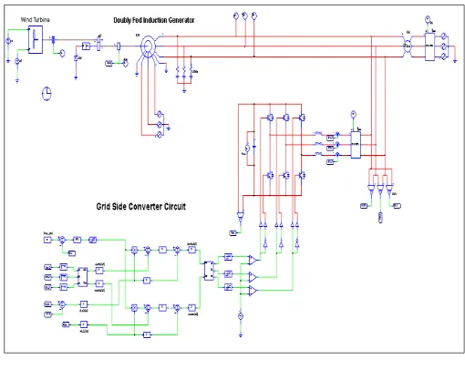
Variable speed operation is essential for large wind turbines in order to optimize the energy capture under variable wind speed conditions. Variable speed wind turbines require a power electronic interface converter to permit connection with the grid. The power electronics can be either partially-rated or fully-rated. A popular interface method for large wind turbines that is based on a partially rated interface is the doubly-fed induction generator system. In the DFIG system, the power electronic interface controls the rotor currents in order to control the electrical torque and thus the rotational speed. Because the power electronics only process the rotor power, which is typically less than 25% of the overall output power, the DFIG offers the advantages of speed control for a reduction in cost and power losses[11][12]. The purpose of grid side converter is to maintain capacitor voltage constant.
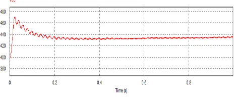
The purpose of the grid converter is to control the DC link capacitor voltage constant to achieve maximum power from the wind over a range of wind velocities. The grid converter control scheme is based on a multi tiered structure that comprises a speed, power and current control loop.
Simulation is shown in figure given below:
Figure 10 Grid side Converter Circuit
[image:4.612.51.288.424.597.2]International Journal of Emerging Technology and Advanced Engineering
[image:5.612.322.578.122.316.2]Website: www.ijetae.com (ISSN 2250-2459,ISO 9001:2008 Certified Journal, Volume 3, Issue 4, April 2013)
Figure 11 DC Link capacitor constant voltage
DFIG characteristics are affected by its injected rotor voltage. By varying the amplitude and phase angle of the rotor injected voltage, the DFIG torque speed characteristics are shifted from the over-synchronous to sub-synchronous speed range to generate electricity and also increases the DFIG pushover torque, thereby improving the stability of operation. The simulated stator real power characteristics of the DFIG show that with increase in the rotor injected voltage, the DFIG real power characteristics shifts more in to the sub-synchronous speed range and the pushover power of the DFIG rises[5]. The increase of Vq results in the expansion of the DFIG torque and real power characteristics for its generating mode, but at the same time increase the inductive reactive power demand from the grid. Whereas, the increase of voltage can not only expand DFIG torque and real power characteristics for its generating mode but also reduces the DFIG inductive power demand and may even change it to capacitive. For both motoring and generating modes, the DFIG sends additional real power through its rotor to the grid. Unlike the stator power, the characteristics of rotor power are mainly influenced by the rotor injected voltage. The simulated stator real power characteristics of the DFIG show that with increase in the rotor injected voltage, the DFIG real power characteristics shifts more in to the sub-synchronous speed range and the pushover power of the DFIG rises. DFIG with closed loop is shown in figure given below:
Figure 12 Doubly Fed Induction Generator Closed loop
Simulation results for doubly fed induction generator are shown in figure given below:
[image:5.612.327.576.361.642.2]International Journal of Emerging Technology and Advanced Engineering
[image:6.612.52.287.134.231.2]Website: www.ijetae.com (ISSN 2250-2459,ISO 9001:2008 Certified Journal, Volume 3, Issue 4, April 2013)
Figure 13 simulation results of DFIG wind turbine
So, from above simulation we are able to know function of DFIG system and also we know the power flow of DFIG system.
The doubly fed machine is a transformer at standstill. The transformer-like characteristics are also present when it is rotating, manifesting itself especially during transients in the grid. Due to the voltage and current behavior described above the rotor will either require, or generate, active power depending on the speed and torque. If the machine is producing torque and operating as a motor, the rotor will generate power if the speed is below synchronous speed. Doubly fed machines are used in applications that require varying speed of the machine's shaft for a fix power system frequency. So doubly fed induction generator system is superior then conventional wind turbine system and has more advantage. So it is very useful in future.
VII. CONCLUSION
After all this simulation doubly fed induction generator can be controlled by rotor side converter as well as grid side converter and to maintain output power to the grid we must have control on that two converter. So that control of doubly fed induction generator through vector control, P-Q calculation and also can apply other controlling methods to doubly fed induction generator to achieve good power output.
REFERENCE
[1] Fthenakis, V. and Kim, H. C. (2009). "Land use and electricity generation: A lifecycle analysis". Renewable and Sustainable Energy Reviews 13 (6–7): 1465
[2] “International Energy Outlook.” Energy Information Administration 2006 p. 66.
[3] "GWEC Global Wind Statistics 2011" Global Wind Energy Commission. Retrieved 15March 2012
[4] “Modeling, Simulation & DFIG Generator for Wind Turbines” Balasubramaniam Babypriya, Rajapalan
[5] “Doubly-Fed Induction Generator for Variable Speed Wind Energy Conversion Systems- Modeling & Simulation” B.Chitti Babu, K.B.Mohanty
[6] “Power Control of a Variable Speed Wind Turbine Driving a DFIG”
D.Aouzella
,
K.Ghedamsi, E.M.Berkouk
[7] “Wind Turbines with Doubly-Fed Induction Generator Systems with Improved Performance due to Grid Requirements” D. Ehlert and H. Wrede
[8] F. Blaabjerg and Z. C. and S. Kramer, “Power electronics as efficient interface in dispersed Power generation systems,” IEEE Transactions on Power Electronics, vol. 19, pp. 1184–1194, Sept 2004.
[9] Dr. John Schonberger, Plexim Gmbh “Modeling a DFIG Wind Turbine System using PLECS” Technoparkstrasse Zurich, December 2008 pp. 2-3
[10] A. Yazdani, R. Iravani, “Voltage-Source Converters in Power Systems”, Wiley, IEEE press 2010 pp 25-150.
[11] The Mathworks Inc., “Simpower system TM 5 Reference”, 2009, pp.2-17-2- 30, 2- 881- 2- 292.
[12] M. Zhao, Z. Chen, F. Blaabjerg, “Load flow analysis for variable speed offshore Wind farms”, IET Renewable Power Generation, volume 3. Iss. 2, 2009, pp. 120-132.
[13] R. Pena, J. Clare, and G. Asher, “Doubly fed induction generator using back-to-back PWM converters and its application to variable-speed wind-energy generation,” IEE Proceedings Electric Power Applications, vol. 143, pp. 231–241, May 1996.