i
DEVELOPMENT OF STEP-COMPLIANT SYSTEM FOR TURN-MILL OPERATIONS
MOHD FAHRURAZI BIN MOHD NOR
A thesis submitted in fulfillment of the requirements for the award
Master in Mechanical Engineering (MDM)
Faculty of Mechanical Engineering and Manufacturing (FKMP)
Universiti Tun Hussein Onn Malaysia
v ABSTRACT
TABLE OF CONTENTS
CHAPTER CONTENT PAGE
TITLE i
ACKNOWLEDGEMENT ii
DEDICATION iii
APPRECIATION iv
ABSTRACT v
TABLE OF CONTENTS vi
LIST OF TABLES vii
LIST OF FIGURES xii
ATTACHMENTS xiii
CHAPTER 1 INTRODUCTION 1
1.1 Background of the study 1 1.2 Objective 3 1.3 Research Scope 4
1.4 Research Methodology 4
CHAPTER 2 LITERATURE REVIEW 10
2.1 Introduction 10
2.2 Milling 10
2.3 Turning 12
2.4 Turn-mill 14
2.5 Standard 14
2.5.1 ARM ISO 14649 15
2.5.2 AIM ISO 10303 AP-238 15
2.6 Data Storage 16
2.7 Basics of CAD, CAPP, CAM and CNC 16
2.8 G & M Code 19
2.9 STEP 20
2.10 STEP-NC 22
2.10.1 Comparing STEP-NC with G-code 23
2.11 TurnSTEP 25
2.12 STEPcNC Converter 26
2.13 Research Work at STEP Tools Inc. 26
2.14 ESPRIT STEP-NC 27
2.15 Super Model Project 28
2.16 WOPturn and STEPturn 29
2.17 Research Work in Japan and China 30
CHAPTER 3 METHODOLOGY 32
3.1 Introduction 32
3.2 Structure of STEP-NC 32
3.2.1 Actual process chain 36
3.2.2 STEP-NC process chain: 37
3.3 Frameworks for the implementation
of STEP compliant CAD/CAM 38
3.3.1 Framework 1: Imports & exports
STEP-NC data 38
3.3.2 Framework 2: External STEP-NC
Interfaced CAD/CAM environment 40
3.3.3 Framework 3: Internally shared
STEP-NC CAD/CAM environment 41
3.4 Discussion on STEP Compliant CAD/CAM
Frameworks 43
3.5 Milling software development 43
3.6 Coding of example 1 milling part 11 45
3.7 Turning software development 49
3.8 Coding of simple turning example part 12 50
3.10 Visual Basic 56
3.11 Sample preparation 56
3.12 Cutting Machine (Automatic Band Saw) 58
3.13 Milling Machine (Vertical Center NEXUS 410A-II) 59
3.13.1 Specifications of Milling Machine (Vertical
Center NEXUS 410A-II) 60
3.14 Turning Machine (Quick Turn NEXUS) 61
3.14.1 Standard Features of Turning Machine (Quick
Turn NEXUS) 62
3.14.2 Specifications of Turning Machine (Quick
Turn NEXUS) 62
CHAPTER 4 RESULT AND DISCUSSION 63
4.1 Introduction 63
4.2 Turn Mill System Operation 63
4.3 Sample manufacturing 72
4.3.1 Part 11 Process Data for Milling 72
CHAPTER 5 CONCLUSION 76
5.1 Introduction 76
LIST OF FIGURES
FIGURE NO. TITLE PAGE
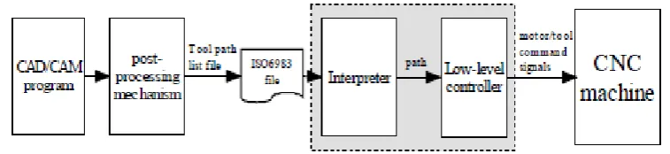
1.1 Scheme of an ordinary CNC machine (Giovanni, 2007) 3
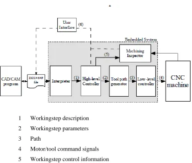
1.2 Scheme of the designed STEP-NC compliant CNC machine
(Giovanni, 2007) 5
2.1 Milling machine (Simon, 1999) 11
2.2 Simple turning machine (Simon, 1999) 12
2.3 Numerical control machine (George, 2010) 13
2.4 Comparison between G & M code and STEP-NC code into NC
machine (Etienne Fortin, 2004) 24
3.1 Example of STEP-NC, ISO 14649-11 example 1 (Newman,
2002) 33
3.2 EXPRESS-G representation of overall schema of turning
STEP-NC data model (Newman, 2002) 34
3.3 CNC actual process chain 36
3.4 STEP-NC process chain 37
3.5 Framework 1 of imports & exports STEP-NC data 39
3.6 Framework 2 of external STEP-NC interfaced CAD/CAM
3.7 Framework 3 of internally shared STEP-NC CAD/CAM
environment 42
3.8 Work piece of the example 1 part 11 (International Standard
Organization (2002) 44
3.9 Work piece of the example part 12 (International Standard
Organization (2002) 49
3.10 Draft of windows 1 54
3.11 Draft of windows 2 54
3.12 Draft of windows 3 55
3.13 Draft of windows 4 55
3.14 Sample preparation for turning, cutting using band saw machine 57
3.15 Sample preparation for milling, cutting using band saw machine 57
3.16 Automatic Band Saw 58
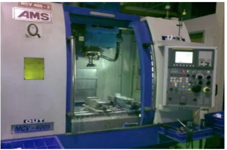
3.17 Mazak Vertical Center NEXUS 410A-II 59
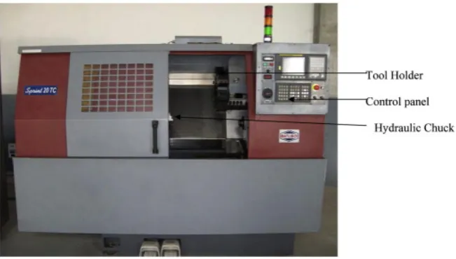
3.18 Mazak Quick Turn NEXUS 61
4.1 Folder location 64
4.2 Main menu of Turn Mill system 64
4.3 Process windows 65
4.4 Characteristic of the operation 65
4.5 Characteristic of the operation fill in with information 66
4.6 Location of the output step-nc coding 66
4.7 Location of the output step-nc file (double click to open) 67
4.9 Step-nc output coding (Maximize window) 68
4.10 Characteristic of the operation with different value 68
4.11 Location of the 2nd output step-nc file 69
4.12 Location of the new output step-nc file (double click to open) 69
4.13 Step-nc new output coding 70
4.14 Reset button 70
4.15 Exit button 71
4.16 Exit menu 71
4.17 Sample manufacturing using Milling Machine (Vertical Center
NEXUS) figure 1 72
4.18 Sample manufacturing using Milling Machine (Vertical Center
NEXUS) figure 2 73
4.19 Sample manufacturing using Milling Machine (Vertical Center
NEXUS) figure 3 73
4.20 Sample manufactured as data model ISO 14649 Part 11 Process
Data for Milling 74
LIST OF TABLES
TABLE NO. TITLE PAGE
3.1 Vertical Center Nexus 410A-II specifications 60
3.2 Mazak Quick Turn NEXUS specifications 62
1 CHAPTER 1
INTRODUCTION
1.1 Background of the study
Numerical control (NC) refers to the automation of machine tools that are operated by abstractly programmed commands encoded on a storage medium, as opposed to manually controlled via hand wheels or levers, or mechanically automated via cams alone. The first NC machines were built based on existing tools that were modified with motors that moved the controls to follow points fed into the system on paper tape. The pursuit for automated manufacturing process control started in 1950s with the introduction of numerical control (NC) machines. These machines had their controller coded in their electronic circuitry and the punch tapes were the only means for loading the part programs onto the controllers. The first numerically controlled machine tool was a three-axis milling machine developed in 1952 at the Servomechanisms laboratory at the Massachusetts Institute of Technology, USA. The
2
Today’s CNC machines have enormous capabilities such as multi-axis control and multi-process manufacture. In the mean time, these capabilities have complicated the programming tasks and made machine tools less adaptable. CNC machines actually use a 50 years old language ISO 6983 also called G-code. A modern CNC system, end-to-end component design is highly automated using CAD/CAM programs. The programs produce a
computer file that is interpreted to extract the commands needed to operate a particular machine via a post processor, and then loaded into the CNC machines for production (James Brittain, 1992).
NC machine tools can be classified as “cutting machines” and “non-cutting machines”. A cutting machine means a machine that performs a material removal process to make a finished part; milling machines, turning machines and EDM machines being good example of such. Non-cutting machine tools change the shape of the blank material by applying force whereby press machines are good examples of this. In addition, robot systems for welding, cutting, and painting can be included in a broad sense. When NC machines were developed, machine parts with complex shape in a precise manner. Therefore, the numerical controller was primarily applied to milling machines and boring machines. However, recently it has become popular to apply NC to increase productivity and this kind of NC machines have been widely varied including machine tools such as turning machines, machining centers, and drill/tapping machines. Particularly, the application of NC has extended to non-conventional machine tools such as wire electro-discharge machines and laser cutting machines in addition to conventional metal-cutting machine tools (Suk-Hwan Suh, 2008).
The introduction of CNC machines has radically changed the manufacturing industry. Curves are as easy as cutting straight lines, complex 3-D structures are relatively easy to
3
Figure 1.1: Schematic of an ordinary CNC machine (Giovanni, 2007)
The importance of CNC technology for the manufacturing to lead the production into a massive improvement interms of the quality and planning for industry. STEP-NC gives a new sign of the new era of modern and smart tools into a new high technology of CNC in the
future.
1.2 Objective of Study
The objectives of this research are:
i. To investigate the effect of applying STEP-NC method on the CNC turn/mill process.
ii. To identify the design process from start to end, for old method from CAD (IGES) to CAM, and for new method CAD (STEP-NC format) to STEP controller.
4 1.3 Research Scope
These research focuses on turn-mill process, from the combination of two main process of the CNC, which is:
i. Turning-Process Data for Turning (ISO 10303-Part 12) ii. Turning-Process Data for Milling (ISO 10303-Part 11)
1.4 Research Methodology
i. Design the sample product using CAD (IGES/STEP-NC) and CAM software;
ii. Sample product (Aluminum) produce with both conventional turn-mill process (CAM/CNC), and intelligent turn-mill process (STEP-NC control/CNC);
iii. The efficiency of both processes will be judge base on; in terms of times, operation and costing;
5 1.5 Background of Research
The changing economic climate has made global manufacturing a growing reality over the last decade, forcing companies from east and west and all over the world to
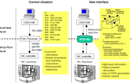
collaborate beyond geographic boundaries in the design, manufacture and assemble of products. The ISO 10303 and ISO 14649 Standards STEP and STEP-NC as shown on Figure. 1.2 have been developed to introduce interoperability into manufacturing enterprises so as to meet the challenge of responding to production on demand. Due to the complexity of programming there is a need to model their process capability to improve the interoperable manufacturing capability of machines such as turn/mill centres. The current ISO 6983 or current CNC regime is considered to rely on low level codes such as the description of tool movements and switching instructions. Today with the latest technology the information beyond tool movement and switching instruction such as tooling, manufacturing features and process sequences are needed to support global adaptability for manufacturing with a specific focus on CNC-based manufacture. STEP-NC is considered to have the necessary rich information including “what to make” and “how to make” (Xun Xu, 2006).
This research focuses on the use of the new standard; ISO 10303 (STEP-NC), to address the process planning and machining of discrete turn/mill components and proposes a STEP Compliant NC structure for generation of ISO 14646 code which can be used for turned component manufacture. The novel application of this work is STEP-NC compliant process control, where the research will utilise and extend the standard for in process measurement at the machine and also explore the application and integration of the STEP-NC standards. The major contribution of this research is the creation of a computational environment for a STEP-NC compliant system for turn/mill operations which is to be used in future.
6
Numerical Control (CNC) machine to produce parts. Codes for CNC have been in conventional language based on ISO 6983 or RS274D (well known as G-code) for 50 years. STEP Tools Inc. has estimated, based on their Super Model Project, that STEP-NC can reduced the machine planning process by up to 75 percent. This is due to a significant reduction in drawing information which is usually generated for productivity. Additionally,
STEP-NC can increase the task of cutter path generation up to 35 percent faster because less information has to be defined since 3D feature recognition is used. And lastly, mid-sized machining jobs can actually be completed in 50 percent less time since STEP-NC provides automation computation for feeds and speeds compensation (Minhat, 2009)
1 Workingstep description 2 Workingstep parameters 3 Path
[image:17.595.83.470.289.618.2]4 Motor/tool command signals 5 Workingstep control information 6 Machining status
7 1.6 Critical Review
A new standard namely ISO 14649 known as STEP-NC is being developed by vendors, users and academic institutes world wide to provide a data model for a new
intelligent CNCs. The data model represents a common standard specifically aimed at NC programming, making the goal of a standardized CNC controller and NC code generation facility a reality (X.W. Xu, 2006).
The review on the 31 papers about STEP-NC during a year 2000 to 2010 has been analyzed to understand the current development of this new technology all over the world. The result has been divided into 3 major items which is technology (milling, turning and turn-mill), standard (ARM ISO 14649 and AIM ISO 10303 AP-238) and data storage (STEP part 28-XML and STEP part 21-text).
In terms of the technology, from the reviewed show that around 87% cover about milling process, and in the year 2006 become the highest number of paper has been published about milling process which is from the total of 27 papers about milling. For the turning process, year 6 papers 2006 and 2008 represent with the highest number of papers which is 2 papers from the total of 6, and overall is 19%. While the turn-mill process, overall percentage only cover with 3% which is the lowest technology has been discussed through the past years.
Currently two versions of STEP-NC are being developed by ISO. The first is the Application Reference Model (ARM) (i.e. ISO 14649) and the other is Application Interpreted Model (AIM) of ISO 14649 (i.e. ISO 10303 AP-238) (X.W. Xu, 2006). ARM ISO 14649 become the important standard referenced for the other authors through the
reviewed with 54%, which is 17 out of 31 papers refer to this standard, while AIM ISO 10303 AP-238 show only 6 out of 31 papers which is 19%.
8
information is captured using XML (Newman, 2008). Recently, there has been a trend of using XML (or rather ISO 10303 Part 28) instead of EXPRESS language (or ISO 10303 Part 21) to represent the STEP-NC information. The reason for this is obvious. The XML processing ability can easily support the e-Manufacturing scenario. CNC machine tools can share information with other departments in and outside the company over the
Internet/Intranet (X.W. Xu, 2006). However the result from the reviewed on the data storage, show that only 9% papers is using XML format, and for the text file format still become the important data storage which is covered by 38%.
STEP-NC Europe is responsible for milling, turning and inspection of the ISO 14649 standard. It has 15 partners, led by Siemens, with users such as Daimler Chrysler, Volvo, and the support of research institutes such as WZL RWTH-Aachen and ISW Stuttgart University. The Swiss are leading the development of the standard for wire-cut and die-sink EDM in collaboration with vendors such as Agie, Starrag and CAM manufacturer CADCAMation. The work in Korea has been carried out by both Pohang University of Science & Technology (PosTECH) and the Seoul National University in the areas of milling and turning architectures for ISO 14649 compliant controllers. Other research teams working in the area include those in the UK and New Zealand. In the United Kingdom, an Agent-Based, STEP-compliant CAM (AB-CAM) system has been developed in Wolfson School of Mechanical and Manufacturing Engineering, Loughborough University. In New Zealand, the Manufacturing Systems Laboratory at the University of Auckland has been using the AIM of STEP-NC to develop a STEP compliant CAPP system for collaborative manufacturing. The STEP-NC programmed in the USA called Super Model led by STEP Tools Inc. and sponsored by National Institute of Standards and Technology (NIST) has made major advances to fully automate the CAD to CNC manufacturing process through the use of STEP or rather AP-238. This project involved a strong group of industrial partners including Boeing, Lockhead Martin, General Electric and General Motors, together with recognized
CAM vendors such as Gibbs Associates and Master CAM (Newman, 2006).
9
already showed major benefits of STEP-NC compared to the existing ISO 6983 standard. The development of the turning data model and applications forms the next step on STEP-NC to a comprehensive standard data interface for manufacturing. The author believes that the turn-mill technology will become the valuable for the future of the CNC technology, the early step taken to understand and explore this technology especially focus on the ISO 10303 part 11
10 CHAPTER 2
LITERATURE REVIEW
2.1 Introduction
Manufacturing equipment undergoes continuous development as newer and better versions/solutions are pushed out into the market almost at a daily basis. To invest and keep pace with the newest technologies is only affordable by few manufacturing companies. Small and medium sized enterprises (SMEs) cannot keep up with the investments, compared with their larger counterparts, and are facing special challenges. During the last few decades much attention has been made to offline programming (generation and transfer of the numerical control code (NC-code)) of CNC machines. There exist three older basic standards for the generation of the numerical control (NC) code namely: ISO 6983, DIN66025 and RS274D. The NC data, from these standards, are often referred to as M and G codes which is apply in millling and turning machine.
2.2 Milling
11
work piece against the rotating cutter, the latter of which is able to cut on its flanks as well as its tip. Work piece and cutter movement are precisely controlled to be less than 0.001 in (0.025 mm) (Noble, David F, 1984), usually by means of precision ground slides and lead screws or analogous technology. Milling machines may be manually operated, mechanically automated, or digitally automated via computer numerical control (CNC). Most CNC milling
[image:22.595.175.404.265.416.2]machines as shown on Figure 2.1 are computer controlled vertical mills with the ability to move the spindle vertically along the Z-axis. This extra degree of freedom permits their use in die sinking, engraving applications, and 2.5D surfaces such as relief sculptures.
Figure 2.1: Milling machine (Jean-François, 2004)
When combined with the use of conical tools or a ball nose cutter, it also significantly improves milling precision without impacting speed, providing a cost efficient alternative to most flat-surface hand-engraving work. CNC machines can exist in virtually any of the forms of manual machinery, like horizontal mills. The most advanced CNC milling-machines, the multi axis machine, add two more axes in addition to the three normal axes (XYZ). Horizontal milling machines also have a C or Q axis, allowing the horizontally
12 2.3 Turning
Turning is the process whereby a single point cutting tool is parallel to the surface. It can be done manually, in a traditional form of lathe, which frequently requires continuous
[image:23.595.137.453.385.622.2]supervision by the operator, or by using a computer controlled and automated lathe machine as shown in Figure 2.2, which does not. This type of machine tool is referred to as having computer numerical control as shown in Figure 2.3, better known as CNC, and is commonly used with many other types of machine tool besides the lathe. Data model for milling can be referring to ISO 14649 Part 12 Process Data for Turning.
Figure 2.2: Simple turning machine (Jean-François, 2004)
13
could even be used to produce complex geometric figures, even the platonic solids; although until the advent of CNC it had become unusual to use one for this purpose for the last three quarters of the twentieth century. It is said that the lathe is the only machine tool that can reproduce itself.
[image:24.595.173.499.361.546.2]The turning processes are typically carried out on a lathe, considered to be the oldest among machine tools, and can be of four different types such as straight turning, taper turning, profiling or external grooving. Those types of turning processes can produce various shapes of materials such as straight, conical, curved, or grooved work piece. In general, turning uses simple single-point cutting tools. Each group of work piece materials has an optimum set of tool angles which have been developed through the years (George, 2010)
14 2.4 Turn-mill
A combination between data model for milling (ISO 14649 Part 11 Process Data for Milling) and data model for turning (ISO 14649 Part 12 Process Data for Turning). A number
of turning and turn–mill machining oriented work have been published as well: Rosso investigated the use of STEP-NC in manufacturing of asymmetric rotational components. It was the researchers’ conclusion that the ISO14649 part 10 milling standard milling features are capable of supporting the features that these complex components require. The necessary data models were created and tested through a prototype system. This research has now been extended by (Y. Yusof, 2008) with the development of an interoperable STEP-NC compliant data model and CAM system for representing and machining of turn–mill components.
2.5 Standard
Nowadays, two versions of STEP-NC are being developed by ISO. The first is the Application Reference Model (ARM) (i.e. ISO 14649) and the other Application Interpreted Model (AIM) of ISO 14649 (i.e. ISO 10303 AP-238. The fact that both STEP-NC ARM (ISO 14649) and AIM (AP-238) co-exist and have each been implemented by different groups, presents a less than satisfactory environment for users. It is of particular importance that one understands the difference between these two ‘‘versions’’ of STEP-NC prior to implementation. The main difference between these two models is the degree to which they use the STEP representation methods and technical architecture.
15
enabled. A major problem with STEP AP-238 though, is that the STEP Integrated Resources used in AP-238 are not adapted to application areas; hence the data in its files are fragmented and distributed. It only provides an information view of the data, whereas the ARM provides a functional view of the data (Xun Xu, 2006).
2.5.1 ARM ISO 14649
ISO14649 informally known as STEP-NC has been proposed as a high-level hierarchical manufacturing information model as a replacement for the low-level machining instructions of ISO6983 and RS274D. In the new standard, tool paths and switching commands have been replaced by a hierarchical information model that contains the feature-based geometry model of the part as well working steps required to manufacture the product. The Application Reference Model (ARM) for STEP-NC has been formalized in ISO14649. The information entities defined within the framework of ISO14649 are capable of supporting manufacturing information and can be tailored for utilization in the adaptive manufacturing system (A. Nassehi, 2006).
2.5.2 AIM ISO 10303 AP-238
ISO 10303 is an ISO standard for the computer-interpretable representation and exchange of product manufacturing information. Its official title is "Industrial automation systems and integration - Product data representation and exchange", known as "STEP" or "Standard for the Exchange of Product model data". STEP-XML is a short term for ISO
16
Another major benefit of STEP-NC is its compliance with ISO 10303, offering an attractive solution to total integration of CAD/CAPP/CAM/CNC without information exchange barriers. Effectively, the Application Interpreted Model (AIM) for ISO 14649, which is an Application Reference Model (ARM), in STEP terminology, is being developed and will become a STEP Application Protocol AP238 (Xun Xu, 2006).
2.6 Data storage
ISO10303-28 specifies the extensible markup language (XML) representation for EXPRESS-driven data and is officially known as STEP-XML. Similar to ISO10303-21, this implementation method specifies the representation of a valid population of STEP entities. Instead of encoding the instances in a text file, however, in part 28 the information is captured using XML. Recently, there has been a trend of using XML (or rather ISO 10303 Part 28) instead of EXPRESS language (or ISO 10303 Part 21) to represent the STEP-NC information. The reason for this is because the XML processing ability can easily support the e-Manufacturing scenario and the CNC machine tools can share information with other departments in and outside the company over the Internet/Intranet (Newman, 2008)
2.7 Basics of CAD, CAPP, CAM and CNC
Prior to the existence of engineering drawings, products were fabricated using traditional measuring devices, such as callipers to transfer measurements or product data. Engineering drawing came into usage in the late 1780’s to provide a more standardized way
17
Mechanical drawings had been used for almost two centuries before CAD came along, whereby product data is represented on a computer often with a screen in a digital form. Indeed, the concept of CAD was brought to a higher level in the late 1960s. A CAD system offers attractive productivity improvement in the product development cycle over the traditional mechanical drawing. For example, with CAD, it is easy to apply design
modifications of an existing model. CAD tools also enable the simulation of a design without fabricating a physical product. CAD can easily output engineering documents such as manufacturing drawings and a Bill of Material (BOM). On the other side of the spectrum of product development process, manufacturing technologies have advanced in a rapid pace since the first CNC machine tool was constructed in 1952. Massachusetts Institute of Technology (MIT) developed the specific language called APT (Automatically Programmed Tool) to support numeric controlled manufacturing. Later, the APT language was adopted by ISO as international standard ISO 6983: Numerical control of machines program format and definition of address words (ISO 6983-1, 1982) in 1982. The ISO 6983 (or G-code) is a Cutter Location (CL) based language. The contour of a component is machined by moving a cutter whose positions are defined in a G-code program (Younis & Wahab, 1997).
In the early days, CAD systems were used to assist engineers to only produce 2-D drawings. In the 1960s, with the appearance of workstations, CAD systems were able to represent 3-D models. The 3-D presentations are mainly in the wireframe format and were not able to support a computer-aided manufacturing solution due to lack of surface information. CAM was first used in 1971 for car body design and tooling. Traditionally, CAM has been considered as an NC programming tool whereas 3D models of components generated in CAD software are used and augmented to generate NC code to drive a CNC machine tool. Around the late 1970s, CAD and CAM systems were brought together for an integrated solution. Dassault Systems Inc. developed a 3D modelling system called CATIA,
18
Nowadays, most of the CAD systems are integrated with CAM functions to provide both design and manufacturing capabilities such as 3D modelling, interactive design, modification, tool path generation and tool path simulation. At the same time, the implementation cost of a CAD/CAM system has been significantly reduced. Small and medium-size enterprises are now able to afford such systems to support their product design
and manufacturing activities. Though integrated in many cases, CAD and CAM have different focuses. The main focus of a CAD system is to model designer’s intent in geometrical terms. CAM systems, on the other hand, concentrate on using computer systems to generate process plans and control the manufacturing operations according to the geometrical information present in a CAD model and existing resources on the shop-floor. In order to fill the gap between design and manufacturing process, computer-aided process planning is needed (Wang et al., 2001).
In a CAPP system, design specifications created in a CAD system are translated into manufacturing information (e.g. product geometry, selection of raw materials, manufacturing operation and sequences, selection of equipment and machine tools and machining operation conditions). This type of information is then translated through part programming into a specification of manufacturing operations and then into the form of G-code, with which manufacturing instructions are executed on a machine tool. The ultimate integration scenario is that of Computer-Integrated Manufacturing (CIM) (Younis & Wahab, 1997).
A CIM system can integrate engineering, production, marketing and other support functions of a manufacturing enterprise. Forming a crucial subset of CIM is so-called Integrated Computer-Aided Manufacturing (ICAM) which encapsulates CAD, CAPP, CAM and CNC. On entering the 21st century, manufacturers are facing increasingly competition in
19 2.8 G & M Code
In ISO 6983, the current standard for numerical control, tool motions are defined using G codes and simple switching instructions are issued by using M codes. This method of
machine programming, results in loss of product information along the manufacturing process chain. As the product geometry designed in CAD software is passed on to the CAPP and CAM software, tool paths and switching instructions specific to an individual machine are generated to optimize the manufacturing effort. The output from the CAM system consists of only low level description of tool paths with all the geometric features and tolerances discarded. There are a number of inherent problems with this traditional process chain; the most important of which is perhaps the one way flow of information. Here, the information generated in the CAD system is passed on to the CAPP system and then onto the CAM system and finally to the machine controller for manufacturing. As a result of this uni-directional information flow, changes made in the final part program generated by the CAM system on the shop floor are not reflected in the product model existing in the CAD/CAM
systems (A. Nassehi, 2006).
G code is a compact, coded set of numbers for axis movements, while STEP-NC is very comprehensive and includes information about features, operations, strategies, cutting tools, and so on. It is very challenging to derive such comprehensive information from the low level G-code information. Low level G and M codes offer very limited information on machine capabilities or work piece characteristics which consequently, results in no information being available on manufacturing processes, inspection plans and work piece attributes in terms of tolerances, etc. and design features to computer numerically controlled (CNC) machines. One solution to the counter the problems is using STEP-NC (ISO 14649) suite of standards, which aim to provide higher-level information for process control (Sanjeev Kumar, 2007).
20
commands for single movement and switching operations but cannot support more complex geometries and logical structures. Therefore it does no longer satisfy the requirements of modern NC technology. The ISO TC184 committee and the European STEP-NC Consortium have members all around the world, who are among the major actors in the machining industry. In substance, they agree that G-Codes are outdated, and are not in sync with the
developments in capabilities of CNC controllers. For those reasons, G-codes stand in the way of increased productivity expected by customers from state of the art machine tools. CAD/CAM systems can handle complex programs and CNC controllers which are also able to perform fairly complex work. Between them, the programming interface used, the G-Codes can only perform tasks that are very limited in complexity. Because the G-G-Codes programming interface is currently used in the industry, the net result are that the controllers are not used to their full potential (Etienne Fortin, 2004).
2.9 STEP
The STEP (ISO10303-(ISO 10303: STandard for the Exchange of the Product data) developed since the 1980s is the data standard for exchanging product data between CAD, CAPP and CAM systems. Product models are well established commercially at the design phase with information relating to geometry, tolerances, functional capability, assemblies etc. already defined in current standards such as STEP (ISO 10303) and represented within CAD systems (Seung-Jun Shin, 2006).
The evolution of STEP can be divided into two release phases. The first major release
of proposed STEP documents occurred in 1988, when a large set of models had been assembled into a single “Integrated Product Information Model” (IPIM). Half a dozen documents from the IPIM were adopted as initial drafts of ISO standards at an SC4 (Sub-Committee 4) meeting in Tokyo in late 1988. By 1989, STEP had focused on the concept of
21
protocols that developing and using them were difficult. In addition, it frequently occurred that different application protocols would use the same type of information (particularly geometry and topology). This led to the development of methods of modularizing APs. The first version of STEP to become an ISO standard was adopted in 1994 and companies such as GE, Boeing, and General Motors began announcing commitments to using STEP in 1995. In
1994/95 ISO published the initial release of STEP as International Standards (IS) with ISO 10303 Parts 1, 11, 21, 31, 41, 42, 43, 44, 46, 101, AP201, and AP203. In the second phase, the capabilities of STEP got widely extended, primarily for the design of products in the aerospace, automotive, electrical, electronic, and other industries. This phase ended in the year 2002 with the second major release, including ISO 10303 APs such as AP202, AP209, AP210, AP212, AP214, AP224, AP225, AP227, and AP232. As of June 2008, the SC4 web site (http://www.tc184-sc4.org/) lists 23 application protocols that have become international standards (Yusof, 2012).
22 2.10 STEP-NC
STEP-NC is a new model for data transfer in the CAD–CAM–CNC chain. It remedies the shortcomings of G code by specifying machining processes rather than the machine tool
motion, using the object-oriented concept of working steps. The working steps represent the essential building blocks of manufacturing tasks. Each working step describes usually a single manufacturing operation using one tool and one strategy. STEP-NC has been newly established as an international standard. Compared with the old standard ISO 6983 (so called M&G-codes) currently used as the interface between CAM and CNC, STEP-NC includes a much richer information set including ‘what-to-make’ (geometry) and ‘how-to-make’ (process plan). Also, STEP-NC has been harmonized with the STEP set of standards as ISO 10303 AP238, which offers the possibility of seamless integration of application throughout design and manufacturing (Seung-Jun Shin, 2006).
STEP-NC is being developed to provide a data model for a new breed of intelligent CNC controllers. The ARM of STEP-NC, i.e. ISO 14649 is made up of several Parts. The general title for STEP-NC is Data Model for Computerized Numerical Controllers representing a common standard specifically aimed at NC programming, making the goal of a standardised CNC controller and NC code generation facility a reality. In 2004, the first set of Parts of ISO 14649 became international standards. Several Parts of ISO 14649 were also adopted as conceptual models by the ISO team developing AIM of STEP-NC, i.e. ISO 10303-238 (or STEP AP238) in the early 2000s, and AP238 was published in 2007. Development of both ISO 14649 and STEP Part 238 continues today. Both of them are commonly known as “STEP-NC”. ISO TC 184/SC4, Industrial data, is developing ISO 10303-238, using the EXPRESS models in ISO 14649 as the domain requirements model
23
i. ISO 14649-1: Overview and fundamental principles (ISO 14649-1, 2003);
ii. ISO 14649-10: General process data (ISO 14649-10, 2004); iii. ISO 14649-11: Process data for milling (ISO 14649-11, 2004); iv. ISO 14649-12: Process data for turning (ISO 14649-12, 2005);
v. ISO 14649-111: Tools for milling (ISO 14649-111, 2003) ; vi. ISO 14649-121: Tools for turning (ISO 14649-121, 2003);
These Parts are arranged hierarchically, in that Part 11 uses Part 10 and Part 111, while Part 12 uses Part 10 and Part 121. Part 10 provides a set of basic capabilities for process planning for machined parts. Parts 11 and 12 specialise these capabilities for milling and turning.
STEP-NC offers the opportunity to effectively maintain high level and standardized information from the design phase to a new breed of intelligent STEP compliant CNC controller. This facilitates bi-directional information exchange with the diverse software CAx systems (e.g. CAD/ CAPP/CAM) in accordance with the manufacturing processes (Sanjeev Kumar, 2007).
2.10.1 Comparing STEP-NC with G-code,
Comparing STEP-NC with G-Code as summarize in Fig. 2.4, there are many benefits using the STEP-NC for manufacturing process, the advantage is:
i. STEP-NC provides a complete and structured data model, linked with geometrical and technological information, so that no information is lost between the different stages of the product development process.
24
iii. The data model is extendable to further technologies and scalable (with Conformance Classes) to match the abilities of a specific CAM, SFP (Shop Floor Programming) or NC systems.
iv. Machining time for small to medium sized job lots can be reduced because intelligent optimization can be built into the STEP-NC controllers.
v. Post-processor mechanism will be eliminated, as the interface does not require machine-specific information.
vi. Machine tools are safer and more adaptable because STEP-NC is independent from machine tool vendors.
[image:35.595.59.519.369.657.2]vii. Modification at the shop-floor can be saved and fed back to the design department hence bi-directional information flow from CAD/CAM to CNC machines can be achieved.
Figure 2.4: Comparison between G & M code and STEP-NC code into NC machine (Etienne
78
REFERENCES
Brittain, James (1992). “Alexanderson: Pioneer in American Electrical Engineering”, Johns Hopkins University Press, pp. 210–211.
Etienne Fortin, Jean-François Chatelain (2004). An Innovative Software Architecture to Improve Information Flow From CAM to CNC” Robotics Computers & Industrial Engineering, vol. 46, n. 4 pp.655-667.
Giovanni Celentano, Francesco Calabrese, “Design and Realization of a STEP-NC Compliant CNC Embedded Controller”. Emerging Technologies and Factory Automation, 2007, pp. 1010 – 1017.
International Standard Organization (2002), ISO 14649 Part 10 General Process Data.
International Standard Organization (2002), ISO 14649 Part 11 Process Data for Milling.
International Standard Organization (2002), ISO 14649 Part 12 Process Data for Turning.
M. Minhat, V.Vyatkin, X.Xu (2009). “A Novel Open CNC Architecture Based on STEP-NC Data Model and IEC 61499 Function Blocks” Robotics and Computer-Integrated
Manufacturing 25, pp.560–569.
79
Red E, Evans M, Jensen G, Bosley J, Luo Y., “Architecture for Motion Planning and Trajectory Control of a Direct Machining Application”, Proceedings of the IASTED International Conference on Control and Applications, 2000, pp. 484-489.
Rosso Jr, R.S.U., Allen, R.D., Newman, S.T., 2002, “Future Issues for CAD/CAM and
Intelligent CNC Manufacture”, paper to be presented at the 19th Int. manufacturing Conference, Belfast.
Rosso Jr, RSU (2005). “STEP Compliant CAD/CAPP/CAM System for Rotational
Asymmetric Parts”. PhD Thesis, Loughborough University, UK Rosso Jr; RSU; Allen RD,
Sanjeev Kumar, Aydin Nassehi.Stephen T. Newman, Richard D. Allen, “Process Control in CNC Manufacturing for Discrete Components: A STEP-NC Compliant Framework”. Robotics and Computer-Integrated Manufacturing, 2007, pp. 667–676
S.H. Suh, J.H. Cho, H.D. Hong (2003), “On the Architecture of Intelligent STEP Compliant CNC,” Computer Integrated Manufacturing, vol. 15, n. 2, pp. 350-362.
Shin, S.,-J., Suh, S.H, & Stoud, I. (2006), Reincarnation of G-Code Based Part Programs into STEP-NC for Turning Applications,” Computer Aided Design, vol.39, pp.1-16.
STEP-NC Newsletters. Issue 3, Nov. 2000.
S. Fujita, T. Yoshida, “OSE: Open System Environment for Controller, 7th International Machine Tool Engineers Conference”, 2001, pp. 234-243.
Suh S, Chung D, Lee B, Cho J, Cheon S, Hong H, Lee H., “Developing an Integrated STEP- Compliant CNC Prototype”. Journal of Manufacturing Systems, 2002, pp. 350-362.
80
Simon, W (1999). “The Numerical Control of Machine Tools”. (Pub)Edward Arnold Super Model.
Wang H.P. and Jain K.L., “Computer Aided Process Planning”, Elsevier 2001.
www.steptools.com/library/stepnc/smp.html
www.materialsengineer.com.
Xu, X.W (2006). “Realization of STEP-NC Enabled Machining” Robotics and Computer-Integrated Manufacturing 22, pp.144–153.
X.W. Xu and S.T. Newman (2006), “Making CNC Machine Tools More Open, Interoperable and Intelligent a Review of the Technologies,” Computers in Industry, vol. 57, n. 2, pp.141-152.
Younis, M.A. and Wahab, A.M.A. (1997),”A CAPP Expert System for rotational components”, Computers and Industrial Engineering, Vol. 33, No. 3-4, pp. 509-512
Yusof, Y. (2009), “STEP-NC-Compliant System for the Manufacturing Environment”, World Academy of Science, Engineering and Technology 49, Dubai. pp 935-940.
Yusof, Y. (2012), “STEP-NC Code Generator on Drilling Operations Using (GEN-M)”, Applied Mechanics and Materials. Vol. 159, pp 267-271.