WIRELESS KNEE JOINT ANGLE MEASUREMENT SYSTEM USING GYROSCOPE
SUKHAIRI BIN SUDIN
A project report submitted in partial fulfillment of the
requirement for the award of the degree
Master of Electrical Engineering
Faculty of Electrical and Electronic Engineering
University Tun Hussein Onn Malaysia
ABSTRACT
Sensors are the eyes of control enabling one to see what is going on. Joint movement measurement system is a type of sensor to give the feedback measurement such angular displacement, angular velocity and angular acceleration. The measurements should be accurate and repeatability in order to get good controller’s performance.
vii
ABSTRAK
CONTENTS
TITLE i
DECLARATION iii
DEDICATION iv
ACKNOLEDGEMENT v
ABSTRACT vi
ABSTRAK vii
TABLE OF CONTENTS viii
LIST OF FIGURES x
LIST OF TABLES xii
CHAPTER 1 INTRODUCTION
1.1 Preamble 1
1.2 Spinal Cord Injury (SCI) 2
1.3 Functional Electrical Stimulator (FES) 4
1.4 Body Angle Measurement 6
1.5 Aim and Objective of the Project 6
1.6 Thesis Outline 7
1.7 List of Publications 7
1.7.1 Conference Paper 8
CHAPTER 2 LITERATURE REVIEW
2.1 Introduction 9
2.2 Body Angle Measurement 9
2.3 Gyroscope 11
2.3.1 Median Filter 13
2.3.2 Kalman Filter 14
2.4 Wireless Communication 15
ix
CHAPTER 3 METHODOLOGY
3.1 Introduction 18
3.2 Angle Measurement 20
3.3 Wireless Communication Data Transmitter 24
3.4 Graphical User Interface (GUI) 26
CHAPTER 4 RESULTS AND ANALYSIS
4.1 Introduction 29
4.2 Data Record 29
4.3 Wired Angle Measurement 30
4.4 Wireless Angle Measurement 33
4.5 Wireless Data Transmitter 36
4.6 Discussion 38
CHAPTER 5 CONCLUSION
5.1 Conclusion 39
5.2 Future Work Recommendation 40
REFERENCES 41
VITA 44
APPENDIX A: Device connection 45
APPENDIX B: Arduino coding 46
APPENDIX C: Matlab GUI coding 48
APPENDIX D1: Wired angle measurement test 1 52
APPENDIX D2: Wired angle measurement test 2 54
APPENDIX D3: Wired angle measurement test 3 56
APPENDIX D4: Wired angle measurement test 4 58
APPENDIX D5: Wired angle measurement test 5 60
APPENDIX E1: Wireless angle measurement test 1 62
APPENDIX E2: Wireless angle measurement test 2 64
APPENDIX E3: Wireless angle measurement test 3 67
APPENDIX E4: Wireless angle measurement test 4 69
APPENDIX E5: Wireless angle measurement test 5 71
APPENDIX F1: 1 meter data transmit test 73
APPENDIX F2: 2 meter data transmit test 75
LIST OF FIGURES
1.1 Spinal cord structure and its damage area 3
1.2 Stimulator electrode on thigh 5
2.1 Sensor placed on thigh and shank with virtual
sensor centre of rotation 10
2.2 Earlier model of gyroscope 11
2.3 schematic diagram of vibratory gyroscope 12 2.4 Comparison unfiltered signal and filtered signal
using median filter 14
2.5 Xbee wireless module 16
3.1 Flowchart process of wireless knee angle measurement 19
3.2 Device configuration 20
3.3 Reference axis for Gyro 1 and Gyro 2 22
3.4 Gyroscope change angle when knee bend 23
3.5 System wear at knee 24
3.6 Xbee attached to Skxbee which connected to PC 25
3.7 X-CTU configuration 26
3.8 Graphical User Interface (GUI) 27
3.9 Origin 90˚ at beginning 28
4.1(a) Wired angle measurement test 1 30
4.1(b) Wired angle measurement test 2 31
4.1(c) Wired angle measurement test 3 31
4.1(d) Wired angle measurement test 4 32
4.1(e) Wired angle measurement test 5 32
4.2(a) Wireless angle measurement test 1 33
4.2(b) Wireless angle measurement test 2 34
xi
4.2(d) Wireless angle measurement test 4 35
4.2(e) Wireless angle measurement test 5 35
4.3(a) Data transmit test for 1 meter 36
4.3(b) Data transmit test for 2 meter 37
LIST OF TABLES
1.1 Nerves served at each spinal part 4
2.1 Previous technique used before to measure body
CHAPTER 1
INTRODUCTION
1.1 Preamble
Sensor is the most important device in closed-loop system that functioned to measure and produce a feedback to complete a cycle of closed-loop system. Mostly, sensors operate and produce analog signal as it output. The big issue that related to all sensors is it accuracy in real time application including lost in communication between sensors and control system. There are many types of sensors with different function and measuring variable and one of them is sensor to measure angle. In Body Sensor Network (BSN) field for medical purpose, body joint angle measurement system is quite important and useful for continuous monitoring in rehabilitation activities especially for Spinal Cord Injury (SCI) patients[1].
Body joint angle measurement system is sensory type systems that provide information about angle movement of body joint. It is usually used at knee and arm joint to monitor the movement while patients do some exercises. This very important and helpful to the therapists and physicians in order to see the effectiveness of rehabilitations training[1-3].
limb abdomen functioned and for SCI patients, they cannot keep their function without help from artificial device such as Functional Electrical Stimulator (FES)[5].
Gait and cycling were the most popular rehabilitations training for SCI patients. In cycling, FES is used to generate a suitable stimulation pattern as contraction to muscle to keep cycling rhythm to make it continuous[6]. The important of joint angle measurement system here is to give a feedback to FES module for further action to make it continuous cycling.
1.2 Spinal Cord Injury (SCI)
Human is the creature with vertebrate that build from the structure of spine that including spinal column and spinal cord. Spine is a block of bone that sits on top of others that link each other by ligament. These links of spine have hole in the centre that call as spinal canal that makes the tube of nervous tissue that known as spinal cord completely surrounded. Spinal cord carries signal and massage from brain to whole body like muscle to make them work[7].
Spinal cord injuries (SCI) are the damage to the cord either it totally or partially damage that affected the nerves ability to carry impulses from brain to muscle or vice versa. Total damage to cord will cause no nerve transmissions can past the site of the injury and this will shut all the sensation and movement capacity below the level of the injury cord. In most cases, damage to the spinal cord are partial and there still have a part of nerve transmission remain that leave patients some sensation or movement capacity below the level of the cord injury[8].
3
[image:11.595.215.423.234.627.2]Structurally spinal cord composed from 31 parts of spinal column that can be divided into 5 different parts: 8 part of Cervical or neck (C1-C8), 12 part of Thoracic or dorsal (T1-T12), 5 part of Lumbar or lower back (L1-L5), 5 part of Sacral or buttock (S1-S5) and 1 Coccyx or tail bone which very small at the bottom end. These structured are illustrated in Figure 1.1, which each level of spinal column have its own nerves function. If the spinal cord injury occurs at certain level from this part it will affect all the nerves below that damage point[7].
Figure 1.1: Spinal cord structure and its damage area[7].
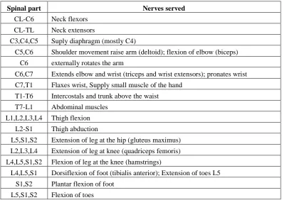
all legs and hands and this happened due to damage at T1 and above. For spinal cord damage from T1 and below, it will drive to paraplegia which means patients will lost their sensation and movement ability for both their left and right legs. America Spinal Injury Association (ASIA) classified that 49.2% from SCI patients experienced paraplegia with 27.9% of complete paraplegia and 21.3% incomplete paraplegia. Most common level of damage for paraplegia occurs at T12[10]. Due to damage of spinal cord not only legs and arms involved, Table 1.1 will explain the nerve at each part of spinal column that will be affected due to damage at that level.
Table 1.1: Nerves served to each spinals part.
Spinal part Nerves served
CL-C6 Neck flexors
CL-TL Neck extensors
C3,C4,C5 Suply diaphragm (mostly C4)
C5,C6 Shoulder movement raise arm (deltoid); flexion of elbow (biceps)
C6 externally rotates the arm
C6,C7 Extends elbow and wrist (triceps and wrist extensors); pronates wrist
C7,T1 Flaxes wrist, Supply small muscle of the hand
T1-T6 Intercostals and trunk above the waist
T7-L1 Abdominal muscles
L1,L2,L3,L4 Thigh flexion
L2-S1 Thigh abduction
L5,S1,S2 Extension of leg at the hip (gluteus maximus)
L2,L3,L4 Extension of leg at knee (quadriceps femoris)
L4,L5,S1,S2 Flexion of leg at the knee (hamstrings)
L4,L5,S1 Dorsiflexion of foot (tibialis anterior); Extension of toes L5
S1,S2 Plantar flexion of foot
L5,S1,S2 Flexion of toes
1.3 Functional Electrical Stimulator(FES)
5
This technique that developed by Moe before Kralj improved it by using low levels of electrical pulse to stimulate the peripheral nervous in skeletal muscle[12].
[image:13.595.150.489.298.481.2]Stimulator electrode was patch directly on the human skin above the target muscle. In order to make shank extend, FES will apply to quadriceps muscle that located on upper thigh while for opposite direction FES will apply at lower part of thigh to interact with hamstring muscle. It was necessary to scrub skin before electrode patched to the skin to minimize the skin-electrode impedance. Electrical pulse that contraction to muscle will cause quadriceps and hamstring muscle fatigue and this will reduce the FES effectiveness[13]. Figure 1.2 illustrated the stimulator patched on the thigh for contraction with quadriceps muscle.
Figure 1.2: Stimulator electrode on thigh[5].
1.4 Body angle measurement
Angle is one of the important parts in geometry which commonly measured in degrees or radians unit. Measurement of angle in geometry subjected to trigonometric function. Degrees are an artificial unit that easily to interpret and shows to other but it’s not related to trigonometric function like radians that more
convenience and always used in calculation.
Body angle measurements always refer to an angle at one of human body joint that affected by movement of two body abdomen linked by that joint. In medical field, human body angle measurement normally done by physiotherapist and one the measuring device used is goniometer[14].
Mostly existing joint angle measurement system is suitable to use in laboratory and require time to setup while it’s a bit expensive[2]. This will create a gap for consumer to use it by their own at home with self exercise. It’s also come
along with such amount of cable connected within reader and controller and it will create a barrier in user movement. Currently system will make user less comfort since it not portable with heavy and large size.
1.5 Aims and objective of the project
The aim of this project is to develop a wireless joint angle movement measurement system for human body joint especially for paraplegic patients due to SCI. In order to achieve this aim, the objectives are formulated as follows:-
i. To investigate on the existing measurement system of joint angle. ii. To develop a portable measuring system that can be used as feedback. iii. To develop a wireless based measurement system to minimize the
7
1.6 Thesis outline
Thesis organization has shown the sequence and step to development of wireless knee joint angle measurement system. This thesis classified into five chapters with follows outline:
First chapter describes on the research induction. The introduction is describing what this project is all about. Aside from that, there are also definition of proposed objectives and scopes for this project, deciding the methods to conduct the study and developing the plan of the project.
Chapter II deals with the literature review of the project. It describes the definition, concepts, principles and tool used in this project. Literature review provides a background of this project and also gives guidelines and direction in this research.
Chapter III deals with a research methodology. This chapter will describe the detailed method that has been used to conduct this research. There are also some explanations on how knee angle has been measured and calculated.
Chapter IV is for the result and discussion. This chapter will highlight the overall of the research outcomes with the results of the neural network. The results consist of graph of angle data from some kind of experiment with different condition. It’s also displayed analysis about the angle error after comparison.
Chapter V consists of conclusion for this study. It also describe the problem arises and recommendations for the future research.
1.7 List of publication
1.7.1 Conference paper
1. S. Sudin and B.S.K.K. Ibrahim, Design and development of wireless joint movement measurement system, in National Conference on Electrical and
Electronic Engineering (NCEEE 2012). 2012, pp.136-138: Johor, Malaysia. (published)
2. S. Sudin, B.S.K.K. Ibrahim, D. Hanafi and M.M.A. Jamil, Knee joint angle measurement system using gyroscope, in IEEE EMBS Conference on
Biomedical Engineering & Science (IECBES 2012), 2012. Langkawi,
CHAPTER 2
LITERATURE REVIEW
2.1 Introduction
There are few types of system that have been developed by other researchers. Each system has its own device and method which contains advantages and disadvantages. The purpose of the system is to produce a system that can be used to measure at human body and can use this measurement output as feedback to other control system. There are also many sensors that can use for angle measurement purpose and one of them is gyroscopes which provide data about angular rate. Type of communication between sensors and controller also a main issue that will affect the effectiveness of the system.
2.2 Body angle measurement
Watanabe and Saito (2011) used body joint angle measurement compared to 3D motion measurement to show the characteristic of human gait. Sensors were placed at various body parts like feet, shank, thigh and back to measure hip, knee and ankle joint angle in short distance while subject walk[2].
[image:18.595.231.408.318.579.2]Dejnabadi. et al. (2005) provided kinematic data from gait analysis to evaluate and qualifying the effect of surgical intervention from body joint angle and focused to knee joint angle. Based this information, it make clinicians easily choose a suitable treatments to patient. Accelerometer and gyroscope have been chosen as measuring sensors that mount on body like illustrated by figure 2.1. These will provide data about angular acceleration and angular velocity[14].
Figure 2.1: Sensor placed on thigh and shank with virtual sensor as center of rotation[14].
11
Table 2.1: Previous technique used before to measure body joint angle
Previous technique Comment
Measuring joint flexion based on resistive
flex-sensor along with extended Kalman filter
(Bakhshi and Mahoor, 2011)
This method produce about 6.92˚ error rate for
knee joint angle measurement
Using conductive fiber that placed at wearable
and comfortable garment to monitor long term
body movement. (Gibbs and Harry, 2004)
Fiber tensions and resistance alterations produce
inconsistence sensor output
Measuring hand joint angle using 20 Hall Effect
sensor that mount an the glove (Dipietro, et al.
2003)
This method comes out with 6.17˚ of error rate
while measuring an angle.
Monitoring knee joint angle using MARG sensor
that include magnetic, angular rate and gravity.
(Kobashi et al. 2008)
This gives a high accuracy but it not suitable to
use as home application because it need high cost
and large size.
2.3 Gyroscope
The idea of Gyroscope was discovered by Johann Bohnenberger in early 1800s. Jean Bernard Leon Foucault (1826-64), the scientist from French was the first person who used the name of gyroscope. It combination two Greek words “gyros” means rotation and “skopeein” means to see. At the beginning, gyroscopes were modeled only to
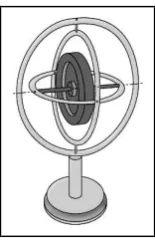
measure the rate of the rotation of an object. Earliest model of gyroscope have been illustrated in figure 2.2[16].
[image:19.595.280.358.585.706.2]Due to large size and high cost of conventional gyroscopes, Micro-Electro-Mechanical System (MEMS) Gyroscope was invented using conventional gyroscopes work concept which produced much cheaper and very small size. MEMS-Gyroscope basically does a measurement for angular rate. Chien-Yu et al. state that Friedland and Hutton proposed equation for the direct angle measurements for vibratory gyroscope in 1978. However, the applicability of these equations was limited only to gyroscope with “ideal” dynamics[17]. Piyabongkarn, et al. (2005)
[image:20.595.271.366.277.383.2]was design and developed a different way of an absolute angle measurement by using MEMS vibratory gyroscope[18].
Figure 2.3 : Schematic diagram of vibratory gyroscope[18].
The basic vibrating gyroscope design like illustrated in figure 2.3 allowed mass to move both in y and x direction by elastic members. Originally function of gyroscope is to measure angular rate and the motion of the system represented by equation (1) and (2):
where θ represent gyroscope rotation around the z axis while and represent
total force that applied to mass in and direction with , ,
13
MEMS gyroscope have many advantages from conventional gyroscope from size, weight and cost, but it usually produce some large drift. Xun Sheng, J., et. al (2006) used combination of median filtering, wavelet decomposition and Adaptive Kalman filter in order to reduce drift in MEMS gyroscope. This combination method reduced gyroscope drift from originally 80.42 deg/h to 18.31 deg/h.[19].
2.3.1 Median filter
Median filter is one of the nonlinear digital filtering techniques. This filter mostly used in image processing to remove noise in order to improve the result but it’s also
can be use in signal processing. Xun Sheng, J., et. al (2006) used this median filtering to reduce noise in gyroscope signal by applying equation as followed:-
Figure 2.4: Comparison unfiltered signal and filtered signal using median filter[19].
2.3.2 Kalman filter
Linear quadratic estimation or most known as Kalman filter was named according to Rudolf E. Kalman around early 1960. This Kalman filter was firstly described and partially developed in technical papers by Swerling (1958), Kalman (1960) and Kalman and Bucy (1961). First idea about Kalman filter appeared when Kalman saw the trajectory estimation problem by the time he visit NASA Research Centre that running Apollo program.
15
modification like the extended Kalman filter, the unscented Kalman filter and the particle filter can be used to estimate state[20].
Kalman filter work as second step in system which it make a prediction of based on previous data after initial condition before real measurement was make. Then the correction will do to make system better. Correction was done by blending prediction and residual[21].
2.4 Wireless communication
Wireless is most important way of communication today. Since the development of this type communication, there have many kind of wireless communication type for each different field. Two way communications in wireless system need a device with transceiver to drive and extract power from the antenna[22]. There is various type of wireless communication today and mostly comes from Radio Frequency (RF).
One of the applications of wireless communication is wireless sensors network (WSN). Recently in many country start using this WSN in the field of military, academia and industrial which attached great important to WSN[23]. Wireless sensors network is a network that consisting various number of device that provide sensing information such as temperature, sound, vibration, pressure, motion, path etc. This WSN now become more noticeable especially in robotic, safety and medical field[24].
2.4.1 ZigBee protocol
Nowadays there were many wireless communication standards like 3G, Wi-Fi, Bluetooth and UWB. This type of communication mostly concentrates on high speed data communication but less consideration on power consumption. However, Zigbee provide very low power consumption that suitable to be used in electronic component for long lasting operation[26].
ZigBee protocol for WSN is rapidly used today in many applications because it provide low transmission power rate between electronic components. It’s suitable
to use in short range data transmission with low cost device and low data rate[27]. Xbee (figure 2.5) is one of the devices that using ZigBee technology as a communication protocol.
[image:24.595.264.373.524.648.2]Zigbee node commonly consists of radio frequency chip that usage of 802.15.4 Standard and high powered by 8 bit MCU. It does can be categorized into two terminal node, router node and coordinator node. Zigbee protocol is a short data range wireless communication protocol which consists of low data rate, low power consumption and low cost. Nowadays Zigbee has been applied in many field such as intelligent building system, safety system, industrial automation, medical equipment, robotic and environmental monitoring system[27].
Figure 2.5: Xbee Wireless Module
17
CHAPTER 3
METHODOLOGY
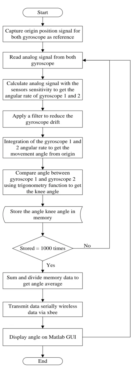
3.1 Introduction
19
Start
Capture origin position signal for both gyroscope as reference
Read analog signal from both gyroscope
Calculate analog signal with the sensors sensitivity to get the angular rate of gyroscope 1 and 2
Integration of the gyroscope 1 and 2 angular rate to get the movement angle from origin
Apply a filter to reduce the gyroscope drift
Compare angle between gyroscope 1 and gyroscope 2 using trigonometry function to get
the knee angle
Store the angle knee angle in memory
Stored = 1000 times
Sum and divide memory data to get angle average
Transmit data serially wireless data via xbee
Display angle on Matlab GUI
End
No
[image:27.595.192.422.58.708.2]Yes
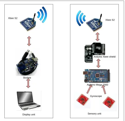
Display unit Sensory unit Xbee S2
Xbee S2
Arduino Xbee shield
[image:28.595.121.522.70.457.2]Gyroscope Arduino Mega 2560 Skxbee
Fig 3.2: Display and sensory unit configuration
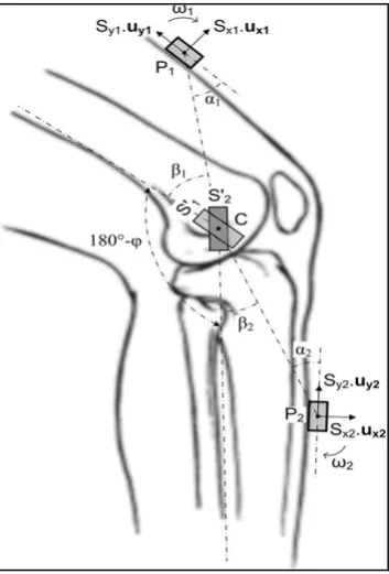
3.2 Angle measurement
Joint angle is measured by comparing the different angle between gyroscope 2 at shank and gyroscope 1 at thigh. Gyroscope will produce 3 axes which z-axis as a reference axis. Angle from z-axis to x-axis and y-axis will be at 90˚ as a initial postion. While SCI patients move their leg, the angle from reference z-axis to new x-axis with y-x-axis as a pivot will change. This change will acknowledge as movement angle for each thigh and shank.
21
measure angle. Idg500 provide angular rate with 2mv/deg/s as its sensitivity to be used to calculate angle from angular rate. Since angular rate is velocity that refers to time in second, angular rate need to sample continuously refer to constant time. Conversion formulas to sample and calculate the angle from angular rate are like follows:-
i- To sample the signal continuously
ii- To get the rotation angle
or
where gyro zero rate output for idg500 is normally 1.35V also known as reference voltage which mean if gyroscope at still position with no movement gyro output voltage will produce same output as gyro zero rate output. According to the rotation gyro output voltage will increase or decrease depends of which direction it rotates. represents sampled analog signal which is time of sampled signal.
Figure 3.3: Reference Axis for Gyro 1 and Gyro 2
Measurement of knee angle from these two gyroscopes by applying trigonometry function to measure a difference or change in both gyroscope. Figure 3.4 illustrated the changes in angle at both gyroscopes when there have a movement. The different in angle change at gyroscope will produce a gap between these two sensors that can be considered as angle at knee bend. Referring to figure 3.4, knee angle can be formulated as follows:-
or
23
Figure 3.4: Gyroscope change angle when knee bend.
This angle must be ensuring by done a comparison with other method of measurement system. Data analysis will be done by comparing this system result with angle measurement that done by using goniometer.
Gyroscope 1
Gyroscope 2
Arduino Mega 2560 With Xbee attached
[image:32.595.119.519.79.371.2]Battery
Figure 3.5: Wearable measuring system on the knee
3.3 Wireless communication data transfer
41
REFERENCES
1. Bakhshi, S., M.H. Mahoor, and B.S. Davidson. Development of a body joint angle measurement system using IMU sensors. in Engineering in Medicine and Biology Society,EMBC, 2011 Annual International Conference of the IEEE.
2. Watanabe, T. and H. Saito. Tests of wireless wearable sensor system in joint angle measurement of lower limbs. in Engineering in Medicine and Biology Society,EMBC, 2011 Annual International Conference of the IEEE.
3. Wagenaar, R.C., et al. Continuous monitoring of functional activities using wearable, wireless gyroscope and accelerometer technology. in Engineering in Medicine and Biology Society,EMBC, 2011 Annual International Conference of the IEEE.
4. Kawashima, N., et al. Novel home-based rehabilitation device to prevent secondary diseases for patients with spinal cord injury. in Rehabilitation Robotics, 2009. ICORR 2009. IEEE International Conference on. 2009. 5. Popovic, L.Z. and N.M. Malesevic. Muscle fatigue of quadriceps in
paraplegics: Comparison between single vs. multi-pad electrode surface stimulation. in Engineering in Medicine and Biology Society, 2009. EMBC 2009. Annual International Conference of the IEEE. 2009.
6. Jiang, H., H. Ao, and C. Ma, RST-based fuzzy TS control strategy for the power control of FES cycling system, in Proceedings of the 4th International Convention on Rehabilitation Engineering \& Assistive Technology, Singapore Therapeutic, Assistive \& Rehabilitative Technologies (START) Centre: Shanghai, China.
7. Wong, A. What is Spinal Injury. [Articles of Public Interest] 2009; Available from:
http://www.nam.org.my/newsmaster.cfm?&menuid=11&action=view&retrie veid=13.
8. LLP, C.G.S.F.B.P. Spinal cord injuries: types and causes 2011 [cited 2012;
Available from:
http://www.cglaw.com/apg_pg28p4_Types_of_Spinal_Cord_Injuries.html. 9. Injury Prevention & Control: Traumatic Brain Injury. Spinal Cord Injury
(SCI): Fact Sheet 2010 [cited 2012; Available from: http://www.cdc.gov/TraumaticBrainInjury/scifacts.html.
10. Schreiber, D. Spinal Cord Injuries. 2011; Available from: http://emedicine.medscape.com/article/793582-overview#a0101.
11. Mirbagheri, M.M., et al., The effects of long-term FES-assisted walking on intrinsic and reflex dynamic stiffness in spastic spinal-cord-injured subjects.
Neural Systems and Rehabilitation Engineering, IEEE Transactions on, 2002.
12. Dingguo, Z., et al., Functional electrical stimulation in rehabilitation engineering: a survey, in Proceedings of the 1st international convention on Rehabilitation engineering \&\#38; assistive technology: in conjunction with 1st Tan Tock Seng Hospital Neurorehabilitation Meeting2007, ACM: Singapore.
13. Levin, O., J. Mizrahi, and E. Isakov, Transcutaneous FES of the paralyzed quadriceps:: is knee torque affected by unintended activation of the hamstrings? Journal of Electromyography and Kinesiology, 2000. 10(1): p. 47-58.
14. Dejnabadi, H., B.M. Jolles, and K. Aminian, A new approach to accurate measurement of uniaxial joint angles based on a combination of accelerometers and gyroscopes. Biomedical Engineering, IEEE Transactions on, 2005. 52(8): p. 1478-1484.
15. Previdi, F. and E. Carpanzano, Design of a gain scheduling controller for knee-joint angle control by using functional electrical stimulation. Control Systems Technology, IEEE Transactions on, 2003. 11(3): p. 310-324.
16. Shkel, C.A.A., MEMS Vibratory Gyroscope : Structural Approaches to Improve Robustness, ed. S.D.S.R.T.H.A.J. Ricco. 2009, United State of America: Springer.
17. Chien-Yu, C. and C. Tsung-Lin. MEMS gyroscope control systems for direct angle measurements. in Sensors, 2009 IEEE. 2009.
18. Piyabongkarn, D., R. Rajamani, and M. Greminger, The development of a MEMS gyroscope for absolute angle measurement. Control Systems Technology, IEEE Transactions on, 2005. 13(2): p. 185-195.
19. Xun Sheng, J., et al. Application of the Digital Signal Procession in the MEMS Gyroscope De-drift. in Nano/Micro Engineered and Molecular Systems, 2006. NEMS '06. 1st IEEE International Conference on. 2006. 20. Simon, D., Kalman filtering with state constraints: a survey of linear and
nonlinear algorithms. Control Theory & Applications, IET. 4(8): p. 1303-1318.
21. Williams, M., Introduction to Kalman Filter, 2003.
22. Iniewski, K., Wireless Technologies: Circuits, System, and Devices. 2008, United State of America: Taylor & Francis Group.
23. Min, Z. and N. Zhang-long. Analysis and design of ZigBee MAC layers protocol. in Future Information Technology and Management Engineering (FITME), 2010 International Conference on.
24. Akribopoulos, O., et al. Building a Platform-Agnostic Wireless Network of Interconnected Smart Objects. in Informatics (PCI), 2011 15th Panhellenic Conference on.
25. Guo Xiong, L., L. Kay Soon, and T. Taher, Unrestrained Measurement of Arm Motion Based on a Wearable Wireless Sensor Network. Instrumentation and Measurement, IEEE Transactions on, 2010. 59(5): p. 1309-1317.
26. Li, P., et al. Research and Application of ZigBee Protocol Stack. in
Measuring Technology and Mechatronics Automation (ICMTMA), 2010 International Conference on.
43
![Figure 1.1: Spinal cord structure and its damage area[7].](https://thumb-us.123doks.com/thumbv2/123dok_us/8777732.902406/11.595.215.423.234.627/figure-spinal-cord-structure-damage-area.webp)
![Figure 1.2: Stimulator electrode on thigh[5].](https://thumb-us.123doks.com/thumbv2/123dok_us/8777732.902406/13.595.150.489.298.481/figure-stimulator-electrode-on-thigh.webp)
![Figure 2.3 : Schematic diagram of vibratory gyroscope[18].](https://thumb-us.123doks.com/thumbv2/123dok_us/8777732.902406/20.595.271.366.277.383/figure-schematic-diagram-vibratory-gyroscope.webp)
![Figure 2.4: Comparison unfiltered signal and filtered signal using median filter[19].](https://thumb-us.123doks.com/thumbv2/123dok_us/8777732.902406/22.595.143.497.69.349/figure-comparison-unfiltered-signal-filtered-signal-median-filter.webp)