Analysis of Switching Overvoltage in Regional Grid with
Small Hydropower Plants
Juan Chen, Haifeng Li
Electric Power College, South China University of Technology, Guangzhou, China Email: [email protected]
Received June2013
ABSTRACT
Present-day small hydropower plants (SHPs) have a large development potential because of the increasing interest in renewable resources and distributed energy generation, therefore, there are many SHPs in places of China where are rich in water resources. However, it has caused overvoltages in the distribution network, and which is even worse for the switching overvoltage such as isolated network operation, changing power supply path. The simple network model is used to analyze the reasons of the switching overvoltage, and the simulation software DIgSILENT/PowerFactory is used to check out the results of the theoretical analysis.
Keywords: Small Hydropower; Isolated Operation; Changing Power Supply Path; Switching Overvoltage
1. Introduction
Hydropower is an important part of global energy pro-duction with a rapid growth in recent years. Therefore, there is a strong demand for the development of SHP (short for small hydropower) for making the most of clean hydropower. Ended to 2005, there are 50,000 SHPs, widely distributed in more than 30 provinces in China, the capacity of which is up to 38,530 MW [1]. The SHPs are constructed in remote mountainous regions, besides, they are primarily runoff hydropower plants defined as providing little or no water storage, of which the active power is nonadjustable, and hard to control [2,3].
Because of the long power transmission distance, the small diameter of the transmission line, and the suppres-sion of the grid voltage, overvoltage and high power fac-tor are common problems of the SHPs [4]. What we should pay more attention to is, when the primary power supply line is cut off, the SHPs still work as an isolated network with the local load. If the power of the SHPs is more than that of the loads, the isolated network will suffer overvoltage and high frequency with damages to the electrical equipment. Additionally, when the primary power supply line requires maintenance, the SHPs should change to another power supply path to prevent the loads’ power from being cut off, in case that the power supply path is changed to a longer one (only this kind of chang-ing power supply path is discussed this paper), which will lead to overvoltage as well.
Currently, researches of SHP mainly focus on two parts, the one is the reasons for overvoltage and high
power factor, including large transmission losses, non-adjustable step-up transformer, and fierce conflicts be-tween the dry season and the wet season [5]; the other is the assessment of SHP’s reactive power based on optimal power flow (OPF) [6]. Although the overvoltage problem of SHP has been involved, there’s no rigorous theoretical derivation for the switching overvoltage especially in isolated operation and changing power supply path.
Therefore, in this paper, theoretical analyses are made for the two kinds of switching overvoltage by the simple network model; and the results of theoretical analysis are verified by the simulation software DIgSILENT/Power- Factory, meanwhile, some effectual advices are proposed to restrain the switching overvoltage.
2. Analysis of Overvoltage in Region Grid
with Small Hydropower
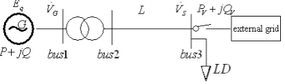
The simple network model given in Figure 1 consists a synchronous generator, a step-up transformer, the trans-mission line, a load and the external network. The syn-chronous generator runs as an isolated network with the local load when the breaker connected to the external network and previously closed is open. Without auto-matic excitation regulator, the SHP can be equivalent to be a constant voltage source with resistance in theoretical analyses.
2.1. Overvoltage in Isolated Operation
Figure 1. Model of a simple network.
faults or other reasons. The voltage of bus3 shown in (1) can be deduced by the model of the simple network.
(
)
2(
)
cos cos 4
2
q q V V
S
E E K R P X Q
V
K
δ+ δ − Σ + Σ
= (1)
where,
(
)
(
2 2)
1 LD LD LD LD
K= + R RΣ +X XΣ R +X , Eq
the no-load voltage of the generator,δis the angle be-tween Eq and VS, ZΣ is the total impedance of the
synchronous generator, transmission line and step-up transformer.
From (1), it can be seen clearly that if PV and QV
reduce to 0, the voltage of bus3 will rise sharply. Actual-ly, the SHPs supply power to both the local loads and the external network (means PV >0, QV >0) in wet season,
when line fault (leading to the isolated operation) occurs frequently by the thunderstorm. Thevenin’s theorem can be used in the complex electricity network, so that the complex network can be equivalent to a constant voltage source with resistance, which is the same as the simple network, so does the analysis method and the conclusion.
2.2. Overvoltage in Changing Power Supply Path
To ensure power distribution reliability, the SHPs change to another power supply path when the primary power supply line requires maintenance. Figure 1 shows that the voltage of bus connected to the external grid is VS,
the power at Eq is P+jQ:
(
)
2
2 cos
q q S
R E Z E V
P
Z
ϕ δ
Σ Σ Σ
Σ
− +
= (2)
(
)
2
2 sin
q q S
X E Z E V
Q
Z
ϕ δ
Σ Σ Σ
Σ
− +
= (3)
where ϕΣ is the impedance angle of ZΣ.
The voltage VS keeps invariable for the suppression
of the external grid, total impedance ZΣ increases.
From (2) we can know that the electromagnetic power of SHP will reduce, while the mechanical power holds changeless because the water inflow keeps the same, thus, the electromagnetic power is less than the mechanical power, so that the rotor speeds up, and the power angle rises up.
The resistance is almost equal to the reactance in dis-tribution network, so we can’t ignore the resistance while making theoretical analysis. In addition, more than 90%
of ZΣ is the transmission line impedance, so the power
angle is about 50˚. Both the increase of the power angle δ and the total impedance ZΣ will decrease the
reac-tive power (see (3)).
At this stage, the power management department take power factor as assessment for the SHPs, if the SHP ge-nerates less reactive power than that required, each 3 Kv rah is equal to the benefit of 1 kWh active power as a punishment. Based on the analysis above, the power fac-tor gets higher and can’t meet the assessment require-ment in changing power supply path, as a consequence, the excitation voltage of the SHPs are raised up.
The reactive power against terminal voltage of SHP can be expressed as (4) according to (3):
(
)
2
2 sin
S q S q G S
S
X E Z E V
Q
Z
ϕ δ′
− +
= (4)
meanwhile
(
)
2 2
sin
S q S
G
S q S
X E Z Q V
Z E ϕ δ
− =
′
+ (5)
where XS is the internal reactance of generator, ϕS is
the impedance angle of ZS, δ ′ is the angle between
q
E and VG.
The impedance angle of ZS is close to 0
[image:2.595.69.277.90.151.2]90 because of the small internal impedance of the generator. From (5) we know that both the increase of δ ′ and Q lead to the increase of VG, similarly, all the bus voltage shown in
Figure 1 will increase, then the whole network suffers from overvoltage while the SHPs’ excitation voltage is raised up at the same time.
3. Case Study
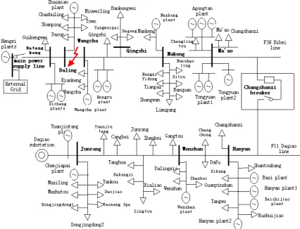
The Shaoguan grid is rich in hydropower resources, where the installed capacity of hydropower has reached 1700 MW at the end of 2005. We select Bibei town Ruyuan district Shaoguan as the overvoltage verification point, because the available water resources reserves amount to 104,500 kW (theoretical potential), the actual available water is up to 76,000 kW and currently there has developed two medium-sized hydropower stations (Hengxi plant) and more than 10 SHPs. Figure 2 shows the distribution network of 10 kV F36 Bibei line of Hengxi plant and 10kV Daqiao line of Daqiao substation, and it has been built for simulation experiments in DIg-SILENT/PowerFactory. Overvoltages are defined in per- unit values (p.u.).
3.1. Overvoltage in Isolated Operation
Figure 2. Distribution network of 10 kV F36 Bibei line of Hengxi plant and 10 kV Daqiao line of Daqiao substation.
Ma’ao operate as an isolated network with the 10 SHPs in 5 hydropower plants, such as Wangcha plant, Hongyu plant, Nankeng plant, Yongyuan plant and Agongtan plant. The bus voltage of Wangcha and Nankeng are shown in Figure 3:
We can see it clearly that the buses’ voltage are all in-creased, the bus voltage of Wangcha rises to 2.342 p.u. from 1.056 p.u., while the bus voltage of Nankeng is up to 2.340 p.u. from 1.066 p.u. Thus, the isolated operation results in serious overvoltage.
3.2. Overvoltage in Changing Power Supply Path
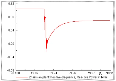
The contacted switch named Changshanzi changes the state from cold standby to hot standby, as a result, the power of Bibei Town is supplied by Daqiao substation instead of Hengxi plant. We disconnect the primary power supply line by opening the outlet circuit breaker of Hengxi plant at t = 30s, and close the Changshanzi breaker at t = 32s to simulate the process of changing power supply path.
It is obvious in Figure 4 and Figure 5 that the bus voltage of Daling reaches the value of 1.21 p.u. from 1.037 p.u., and the bus voltage of Wangcha is up to 1.202
Figure 3. Bus voltage of Datangkeng and Guikeng in iso-lated operation.
[image:3.595.309.537.448.623.2]Figure 4. Bus voltage of Daling and Wangcha in changing power supply path.
Figure 5. The reactive power of Zhaimian plant in changing power supply path.
4. Some Effective Measures to Restrain
Switching Overvoltage in Region Grid
There are many measures to restrain overvoltage, the following three must be more effective.
1) Put into intelligent automatic bus transfer equip-ment. The quality of voltage and frequency in the iso-lated network are too poor which can often damage the electrical appliances. The conventional automatic bus transfer equipment has the defect of needing more time to detect bus non-voltage, at the cost of islanding all the SHPs and taking a very long time to restore power supply. In this case, not only the power quality is poor, but also the reliability of power supply is low. The automatic bus transfer has two modes, the one is that the SHPs are quickly selected and tripped in low water period, while the other one (in the mode of high frequency) is that the SHPs are tripped round by round and the automatic syn-chronous capture reclose in high flow period, which enables regional power supply to restore more quickly and has greatly improved the quality of frequency and voltage [7].
2) Equip the small hydropower with automatic excita-tion regulator. As we all know that the AVR (short for automatic excitation regulator) can regulate the voltage automatically, better distribution of the system’s reactive power. It is clear from formulas (2) and (3) thatEqhas a significant effect on the active power and reactive power of the generators. The unbalanced power which can cause great disturbance to the system and is not condu-cive to the stability of the system can be reduced by the regulation of the AVR. Putting into the AVR for SHPs has significant effect on restraining overvoltages.
Install the voltage control terminal of smart distribu-tion grid in the load side. The voltage control terminal makes use of the modern power electronic technology, and its primary components include silicon controlled rectifier and the PWM inverter, which can effectively achieve the isolation and control of the voltage. The ter-minal can convert the unqualified voltage into the one that become available to be used by the user directly, so as to keep the overvoltages from damaging the electrical equipment effectively.
5. Conclusions
On the basis of the analysis of theory and simulation in overvoltages, the following conclusions can be drawn:
1) There will be severe overvoltages in isolated opera-tion, changing power supply path and stepping into the wet season.
2) Some effective measures have been proposed to re-strain overvoltage in region grid, like putting into intelli-gent automatic bus transfer equipment in order to restore power supply more quickly; equipping the SHPs with AVR to regulate the too high or too low voltage auto-matically; and installing the voltage control terminal in the load side to prevent the overvoltages from damaging the electric equipment.
6. Acknowledgements
The work described in this paper is supported by Guangdong Special Fund Project of Industry, University and Research Institute Collaboration (2011A090200127, 2011A090200074).
REFERENCES
[1] X. Chen, “Technology Development of the Small Hy- dropower Resources in China,” Rural Electrification, Vol. 1, 2006, pp. 40-42.
[2] T. F. Zhou and Z. Y. Wang, “The Problems and Coun- termeasures of Small Hydropower Development and Construction in China,” China Rural Water and Hydro- power, Vol. 2, 2007, pp, 82-84.
[image:4.595.58.289.280.441.2]Water and Hydropower, Vol. 3, 2004, pp. 82-83.
[4] H. L. Zhang and L. G. Liu, “Voltage and Reactive Power of Small Hydropower System and Study on Control Strategy,” Master Thesis, North China Electric Power University, Beijing, 2010.
[5] X. H. Fang, “Management of Voltage and Reactive Pow- er of Small Hydropower,” Rural Electrification, Vol. 7, 2008.
[6] L. QIAO, L. Guo and R. Zhang, “Estimated Means of
Reactive Power for Distributed Small Hydropower Based on Optimal Power Flow,” Proceedings of the Chinese So- ciety of Universities, Vol. 2, 2008.
[7] Z. F. Chen, Y. Wu and D. Q. Jin, “Research on Intelligent Automatic Bus Transfer Equipment Suitable for the Small Hydroelectric Power System in Mountainous Area,”